JP2014178043A - Air conditioning system - Google Patents
Air conditioning system Download PDFInfo
- Publication number
- JP2014178043A JP2014178043A JP2013050472A JP2013050472A JP2014178043A JP 2014178043 A JP2014178043 A JP 2014178043A JP 2013050472 A JP2013050472 A JP 2013050472A JP 2013050472 A JP2013050472 A JP 2013050472A JP 2014178043 A JP2014178043 A JP 2014178043A
- Authority
- JP
- Japan
- Prior art keywords
- duct
- air
- discharge
- circulation duct
- conditioned air
- Prior art date
- Legal status (The legal status is an assumption and is not a legal conclusion. Google has not performed a legal analysis and makes no representation as to the accuracy of the status listed.)
- Granted
Links
Images

Landscapes
- Central Air Conditioning (AREA)
- Ventilation (AREA)
- Duct Arrangements (AREA)
- Air Conditioning Control Device (AREA)
Abstract
【課題】工場などの広い場所に適用する場合に、消費エネルギーをより抑制できる空調システムを提供する。
【解決手段】空調システムは、環状に形成された循環ダクト11と、循環ダクト11内に設けられ、循環ダクト11内の空気を循環させる送風機32と、循環ダクト11内に設けられ、通過する空気に対して調和処理を施す熱交換器31と、循環ダクト11から分岐して設けられ、循環ダクト11内の調和空気を循環ダクト11の外へ排出する排出ダクト13〜15と、排出ダクト13〜15からの調和空気の排出を許可する状態と規制する状態とを切り替える弁61〜63と、循環ダクト11に連通され、循環ダクト11の外から空気を吸入する吸入ダクト12とを備える。
【選択図】図3An air conditioning system capable of further reducing energy consumption when applied to a wide place such as a factory.
An air conditioning system includes a circulation duct 11 formed in an annular shape, a blower 32 that circulates air in the circulation duct 11, and air that is provided in and passes through the circulation duct 11. A heat exchanger 31 that performs a harmony process on the air, a discharge duct 13 to 15 that branches off from the circulation duct 11 and discharges the conditioned air in the circulation duct 11 to the outside of the circulation duct 11, and a discharge duct 13 to 15 includes valves 61 to 63 that switch between permitting and restricting discharge of conditioned air from 15, and a suction duct 12 that communicates with the circulation duct 11 and sucks air from outside the circulation duct 11.
[Selection] Figure 3
Description
本発明は、工場や広い場所などに好適に用いられる空調システムに関するものである。 The present invention relates to an air conditioning system that is suitably used in factories and large places.
工場内のスポット空調設備が特開2008−175507号公報(特許文献1)に記載されている。特許文献1には、工場内に複数の室内機を設け、各室内機の吹出口付近に設けられた人感センサが人の存在を検知した場合に、室内機を運転させることが記載されている。また、特開平9−170796号公報(特許文献2)には、広い場所に人が点々と存在する場合に、その場所のみをスポット的に冷暖房することが記載されており、特にエアカーテンの冷暖気を吹き出すことが記載されている。 A spot air-conditioning facility in a factory is described in JP 2008-175507 A (Patent Document 1). Patent Document 1 describes that a plurality of indoor units are provided in a factory, and the indoor unit is operated when a human sensor provided near the air outlet of each indoor unit detects the presence of a person. Yes. Japanese Patent Application Laid-Open No. 9-170796 (Patent Document 2) describes that when there are many people in a wide area, only the area is spot-cooled and heated. It is described to blow out.
ところで、家屋やビルなどの比較的狭い室内に適用される空調機においては、室内にて調和空気を循環させることで、空調設備の消費エネルギーを抑制している。しかし、工場などの広い場所においては、工場全領域を冷暖房することは、却って消費エネルギーを増大することになる。そこで、上述したように、スポット的に冷暖房している。特許文献1においては、必要なときに室内機を稼働することで、消費エネルギーを抑制しているが、改善の余地がある。 By the way, in an air conditioner applied to a relatively small room such as a house or a building, energy consumption of the air conditioning equipment is suppressed by circulating conditioned air in the room. However, in a large place such as a factory, cooling and heating the entire factory area increases energy consumption. Therefore, as described above, air conditioning is performed in a spot manner. In Patent Document 1, energy consumption is suppressed by operating an indoor unit when necessary, but there is room for improvement.
本発明は、このような事情に鑑みてなされたものであり、工場などの広い場所に適用する場合に、消費エネルギーをより抑制できる空調システムを提供することを目的とする。 The present invention has been made in view of such circumstances, and an object of the present invention is to provide an air conditioning system that can further reduce energy consumption when applied to a wide place such as a factory.
そこで、本発明者は、調和空気の少なくとも一部を循環させることを思いつき、本発明を想到するに至った。
すなわち、本手段に係る空調システムは、環状に形成された循環ダクトと、循環ダクト内に設けられ、循環ダクト内の空気を循環させる送風機と、循環ダクト内に設けられ、通過する空気に対して調和処理を施す熱交換器と、循環ダクトから分岐して設けられ、循環ダクト内の調和空気を循環ダクトの外へ排出する排出ダクトと、排出ダクトからの調和空気の排出を許可する状態と規制する状態とを切り替える弁と、前記弁が許可する状態の場合に、前記循環ダクトから前記排出ダクト側に分岐する前記調和空気の流量を設定する流量調整弁と、循環ダクトに連通され、循環ダクトの外から空気を吸入する吸入ダクトとを備える。
Therefore, the present inventor has conceived to circulate at least a part of the conditioned air and has come up with the present invention.
That is, the air conditioning system according to the present means includes a circulation duct formed in an annular shape, a blower provided in the circulation duct for circulating the air in the circulation duct, and the air provided in the circulation duct for passing air. A heat exchanger that performs harmonization, a discharge duct that branches off from the circulation duct, discharges the conditioned air in the circulation duct to the outside of the circulation duct, and a state and regulation that permits discharge of the conditioned air from the discharge duct A valve that switches between a state to be performed, a flow rate adjusting valve that sets a flow rate of the conditioned air that branches from the circulation duct to the discharge duct in a state that the valve permits, and a circulation duct that communicates with the circulation duct A suction duct for sucking air from outside.
本手段によれば、弁により調和空気の排出を規制する状態においては、循環ダクト内を調和空気が循環し続ける。ここで、吸入ダクトが循環ダクトに連通しているが、送風機の出力が一定の場合に、調和空気が排出ダクトから外へ排出されなければ、吸入ダクトから循環ダクト内へ新たな空気が流入しない。従って、熱交換器を通過する空気は、既に熱交換器によって調和された空気となる。そのため、熱交換器を通過する際に、熱交換器によるエネルギーをほとんど消費しない。このように、排出ダクトから調和空気を排出しない状態を継続する間、エネルギーはほとんど消費しない。 According to this means, the conditioned air continues to circulate in the circulation duct in a state where the discharge of the conditioned air is regulated by the valve. Here, the suction duct communicates with the circulation duct, but when the output of the blower is constant, new air does not flow into the circulation duct from the suction duct unless the conditioned air is discharged from the discharge duct. . Therefore, the air passing through the heat exchanger is already conditioned by the heat exchanger. Therefore, little energy is consumed by the heat exchanger when passing through the heat exchanger. Thus, energy is hardly consumed while continuing the state which does not exhaust conditioned air from an exhaust duct.
一方、弁により調和空気の排出を許可している場合には、循環ダクト内を循環する調和空気の一部が排出ダクトから排出され、調和空気の残りの一部が循環ダクトを循環する。排出ダクトから調和空気の一部が排出されることで、排出ダクト付近を確実に冷暖房できる。循環ダクトを循環する調和空気の残りの一部は、熱交換器を再び通過することになる。ここで、熱交換器を通過する空気量は、送風機の出力によって決定される。送風機の出力が一定であれば、排出ダクトから排出された調和空気に相当する量の新たな空気が、吸入ダクトから吸入される。従って、吸入ダクトから吸入された新たな空気と既に調和処理を施された調和空気との混合空気に対して熱交換器による調和処理が施される。このように、排出ダクトから排出した調和空気に相当する量の新たな空気に対して、熱交換器はエネルギーを消費することになる。従って、消費エネルギーを低減できる。 On the other hand, when discharge of conditioned air is permitted by the valve, a part of the conditioned air circulating in the circulation duct is discharged from the discharge duct, and the remaining part of the conditioned air circulates in the circulation duct. By discharging a part of the conditioned air from the discharge duct, the vicinity of the discharge duct can be reliably cooled and heated. The remaining part of the conditioned air that circulates in the circulation duct will pass through the heat exchanger again. Here, the amount of air passing through the heat exchanger is determined by the output of the blower. If the output of the blower is constant, an amount of new air corresponding to the conditioned air discharged from the discharge duct is sucked from the suction duct. Therefore, the harmony process by a heat exchanger is performed with respect to the mixed air of the new air suck | inhaled from the suction duct and the already conditioned air. Thus, the heat exchanger consumes energy for the amount of new air corresponding to the conditioned air exhausted from the exhaust duct. Therefore, energy consumption can be reduced.
本手段の空調システムの好適な態様について以下に説明する。
吸入ダクトは、排出ダクトから排出される調和空気の量に対応する量の非調和空気を吸入する。つまり、吸入ダクトから吸入される空気は、調和空気ではなく、非調和空気である。上述したように、熱交換器によって調和される空気には、吸入ダクトから吸入される非調和空気のみではなく、循環される調和空気が含まれる。従って、排出ダクトから調和空気が排出される場合に、吸入ダクトから非調和空気が吸入されるとしても、熱交換器を通過する空気の一部が非調和空気となるだけであるため、確実に熱交換器による消費エネルギーを低減できる。
A preferred embodiment of the air conditioning system of this means will be described below.
The suction duct sucks in an amount of non-conditioned air corresponding to the amount of conditioned air discharged from the discharge duct. That is, the air sucked from the suction duct is not conditioned air but non-conditioned air. As described above, the air conditioned by the heat exchanger includes not only non-conditioned air sucked from the suction duct but also circulated conditioned air. Therefore, when conditioned air is discharged from the exhaust duct, even if non-conditioned air is sucked from the suction duct, only a part of the air passing through the heat exchanger becomes non-conditioned air. Energy consumption by the heat exchanger can be reduced.
また、吸入ダクトは、循環ダクトにおいて排出ダクトと熱交換器の上流側との間に連通されるとよい。これにより、熱交換器によって調和された空気は、吸入ダクトから排出されることなく、排出ダクトから排出されるか、再び熱交換器の上流側へ循環される。従って、排出ダクト付近における冷暖房効果を確実に発揮しつつ、消費エネルギーを低減できる。 Further, the suction duct may be communicated between the exhaust duct and the upstream side of the heat exchanger in the circulation duct. Thereby, the air conditioned by the heat exchanger is discharged from the discharge duct or circulated again upstream of the heat exchanger without being discharged from the suction duct. Therefore, energy consumption can be reduced while the air-conditioning effect in the vicinity of the discharge duct is reliably exhibited.
また、空調システムは、複数の排出ダクトおよび複数の弁を備えるようにしてもよい。複数の排出ダクトを備えるようにすることで、スポット的に冷暖房効果を発揮できる場所を複数にすることができる。それぞれの排出ダクトに弁を設けることで、複数の排出ダクトのうち必要なダクトのみから調和空気を排出することができる。このように、消費エネルギーを必要な分だけにすることができる。 The air conditioning system may include a plurality of exhaust ducts and a plurality of valves. By providing a plurality of discharge ducts, a plurality of places where the air-conditioning effect can be exhibited in a spot manner can be provided. By providing a valve in each discharge duct, conditioned air can be discharged from only a necessary duct among the plurality of discharge ducts. In this way, energy consumption can be reduced to the required amount.
吸入ダクトは、常時開放状態としてもよい。吸入ダクトを常時開放状態としても、上記作用効果を生じる。また、吸入ダクトを常時開放状態に設置することは、低コスト化につながる。 The suction duct may be always open. Even if the suction duct is always open, the above-described effects are produced. Moreover, installing the suction duct in an always open state leads to cost reduction.
(空調システムの構成)
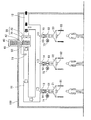
本実施形態の空調システムの構成について図1を参照して説明する。空調システムは、例えば、工場などの広い場所に適用される。当該空調システムは、工場全体を空調するのではなく、工場における局所的(スポット的)な部位に調和空気を排出する。
(Configuration of air conditioning system)
The structure of the air conditioning system of this embodiment is demonstrated with reference to FIG. The air conditioning system is applied to a wide place such as a factory. The air conditioning system does not air-condition the entire factory, but exhausts conditioned air to local (spot-like) parts in the factory.
空調システムは、図1に示すように、循環ダクト11、吸入ダクト12、排出ダクト13〜15、排出フード21〜23、室内機30、室外機40、冷媒配管42、制御装置50、温度センサ51、弁61〜63、モータ71〜73、人感センサ81〜83および流量調整弁91〜93を備える。
As shown in FIG. 1, the air conditioning system includes a
循環ダクト11は、環状に形成されており、工場の天井に設置される。図1において、循環ダクト11は、上下方向(高さ方向)に循環するように示しているが、天井に沿って(水平に)循環するように設置している。循環ダクト11は、内部を調和空気が流通する。そこで、循環ダクト11は断熱材により形成され、内部を流通する調和空気の熱が循環ダクト11の外部へ伝達されにくい。
The
吸入ダクト12は、一端を常時開放状態とされ、他端を循環ダクト11に連通される。つまり、吸入ダクト12は、循環ダクト11の外から空気を吸入し、吸入した空気を循環ダクト11へ誘導する。吸入ダクト12は、工場の外側に開口させてもよいし、工場の内側に開口させてもよい。ここで、工場全体が空調されているわけではないので、吸入ダクト12から吸入される空気は、非調和空気となる。
One end of the
排出ダクト13〜15は、それぞれ循環ダクト11から分岐して設けられ、循環ダクト11内の調和空気を循環ダクト11の外へ排出する。排出ダクト13〜15は、工場内において調和空気を排出したい場所に設けられる。例えば、工場内において、作業者が作業する場所に調和空気を排出できるように、排出ダクト13〜15が設けられる。ここで、図1には、3つの排出ダクト13〜15を示すが、1つ、2つでもよいし、4つ以上とすることもできる。排出ダクト13〜15は、循環ダクト11と同様に、断熱材により形成される。
The
排出フード21〜23は、排出ダクト13〜15のそれぞれの先端に一体的に設けられる。排出フード21〜23は、作業者による作業場所の上方に配置される。排出フード21〜23から排出される調和空気は、作業場所を囲むようなカーテン状に形成される。カーテン状の調和空気により囲まれた内側領域では、温湿度を所望値に保つことができる。
The
室内機30は、循環ダクト11内に設置される。室内機30は、通過する空気に対して調和処理を施す熱交換器31を備える。また、室内機30は、循環ダクト11内の空気を循環させる送風機32を備える。送風機32は、熱交換器31の上流側に配置される。図1において、循環ダクト11内の調和空気は、反時計回りに循環する。ここで、室内機30は、循環ダクト11と吸入ダクト12との連通部位より僅かに下流側に設けられる。換言すると、吸入ダクト12が、室内機30の直ぐ上流側に連通される。つまり、吸入ダクト12は、循環ダクト11において排出ダクト13〜15と室内機30の熱交換器31の上流側との間に連通される。
The
室外機40は、工場の屋外に設置する。図1においては、室外機40は、工場の屋上に設置する。もちろん、室外機40を地面や他の場所に設置してもよい。室外機40は、熱交換器41を備える。冷媒配管42が、室内機30の熱交換器31と、室外機40の熱交換器41との間を循環する。これにより、室内機30の熱交換器31を通過する空気に対して調和処理を施すことができる。
The
温度センサ51は、循環ダクト11内であって、室内機30より僅かに下流側に配置される。温度センサ51は、通過する調和空気の温度を検知する。制御装置50は、温度センサ51の検出値に基づいて、調和空気の温度が所望値となるように、室内機30および室外機40を制御する。例えば、空調システムを冷房として機能させる場合に、調和空気の温度が所望値より高い場合には、制御装置50は室内機30および室外機40を制御することによって冷却能力を高める。一方、調和空気の温度が所望値に一致する場合には、制御装置50は、室内機30および室外機40は冷却能力を発揮させない。
The
また、温度センサ51は、排出フード21〜23の下方、すなわち調和空気により囲まれた内側領域に配置してもよい。この場合、温度センサ51は、作業領域の温度を直接検知している。従って、作業領域の温度が所望値になるように、室内機30および室外機40が制御される。また、温度センサ51は、排出ダクト13〜15のそれぞれ、または、排出フード21〜23のそれぞれに配置してもよい。この場合、排出フード21〜23から排出される調和空気の温度が所望値になるように、室内機30および室外機40が制御される。
Moreover, you may arrange | position the
弁61〜63は、独立して駆動可能であって、排出ダクト13〜15のそれぞれに開閉可能に設けられる。弁61〜63は、循環ダクト11から排出ダクト13〜15を通過して排出フード21〜23の外への調和空気の排出を許可する状態(以下、「許可状態」と称する)と、調和空気の排出を規制する状態(以下、「規制状態」と称する)とを切り替える。モータ71〜73は、弁61〜63のそれぞれを駆動し、許可状態と規制状態とを切り替える。
The
モータ71〜73は、人感センサ81〜83による検知に基づいて制御される。人感センサ81〜83は、排出フード21〜23のそれぞれに設けられ、排出フード21〜23の下方領域(作業者による作業場所)に人間が存在するか否かを検知する。人感センサ81〜83には、例えば、動作検知センサや、熱検知センサなどが適用される。そして、人感センサ81〜83によって人間を検知した場合に、対応するモータ71〜73が弁61〜63を規制状態から許可状態に切り替える。反対に、人間の存在を検知しなくなると、対応するモータ71〜73が弁61〜63を許可状態から規制状態に切り替える。
The
流量調整弁91〜93は、排出ダクト13〜15のそれぞれに設けられる。流量調整弁91〜93は、図1においては弁61〜63より上流側に設けられる場合を示しているが、弁61〜63の下流側に設けてもよい。流量調整弁91〜93は、通過する調和空気の流量を設定値とするように機能する。従って、弁61〜63が許可状態(開放状態)の場合に、循環ダクト11から排出フード21〜23側へ分岐する調和空気の流量は、流量調整弁91〜93で設定された量となる。例えば、弁61が許可状態(開放状態)の場合であっても、弁61〜63の全てが許可状態の場合であっても、排出フード21から排出される調和空気の流量は流量調整弁91により設定された流量となる。
The
ここで、流量調整弁91〜93の例として、定流量弁を用いることができる。この場合、定流量弁としての流量調整弁91〜93は、通過する調和空気の流量を一定値とするように機能する。従って、弁61〜63が許可状態(開放状態)の場合に、排出フード21〜23から排出される調和空気の量は、一定となる。なお、流量調整弁91〜93は、排出ダクト13〜15の他に、排出フード21〜23に設けてもよい。
Here, as an example of the flow
(空調システムの動作)
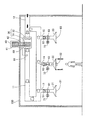
次に、上述した空調システムの動作について図1〜図3を参照して説明する。ここで、図1〜図3において、矢印の幅は、通過する空気の流量に対応する。つまり、矢印の幅が大きいほど、通過する空気の流量が多いことを意味する。また、白抜き矢印は、調和空気を示し、黒矢印は、非調和空気を示し、斑矢印は調和空気と非調和空気の混合空気を示す。
(Air conditioning system operation)
Next, the operation of the above-described air conditioning system will be described with reference to FIGS. Here, in FIG. 1 to FIG. 3, the width of the arrow corresponds to the flow rate of the passing air. In other words, the larger the width of the arrow, the greater the flow rate of the passing air. Also, the white arrow indicates conditioned air, the black arrow indicates non-conditioned air, and the uneven arrow indicates mixed air of conditioned air and non-conditioned air.
以下に、作業場所全てに作業者が存在しない場合、工場内の3箇所の作業場所全てに作業者が存在している場合、1箇所の作業場所に作業者が存在している場合のそれぞれについて説明する。 Below, when there are no workers at all work places, there are workers at all three work places in the factory, and when there are workers at one work place, respectively. explain.
まず、工場内の3箇所の作業場所全てに作業者が存在していない場合について、図2を参照して説明する。室内機30および室外機40が駆動されている。従って、送風機32による出力に応じた量の空気が室内機30の熱交換器31を通過する。熱交換器31を空気が通過することで、通過する空気が調和処理を施される。つまり、当該空気が冷房処理または暖房処理される。調和処理は、室内機30の下流側に配置される温度センサ51の温度が所望値となるように行われる。
First, the case where the worker does not exist in all the three work places in the factory will be described with reference to FIG. The
ここで、図2においては、工場内の3箇所の作業場所全てに作業者が存在しないため、人感センサ81〜83が人間を検知しない。そうすると、弁61〜63が、循環ダクト11内の調和空気を排出ダクト13〜15から排出させない状態(規制状態)となる。つまり、循環ダクト11内の調和空気は、排出フード21〜23から外へ排出されることはない。
Here, in FIG. 2, since there are no workers at all three work places in the factory, the
そうすると、循環ダクト11内を流通する調和空気は、排出ダクト13〜15側へ分岐されることなく、そのまま循環ダクト11内を流通し続ける。従って、室内機30から下流側に送り出された調和空気の全てが、室内機30の上流側に戻ってくる。
If it does so, the conditioned air which distribute | circulates the inside of the
ここで、循環ダクト11には、常時開放状態とされている吸入ダクト12が連通している。しかし、送風機32の出力が一定の場合に、循環ダクト11内の調和空気が排出ダクト13〜15から外へ排出されなければ、吸入ダクト12から循環ダクト11内へ新たに空気が吸入することはない。そのため、室内機30の熱交換器31を再び通過する空気は、既に熱交換器31によって調和処理を施された空気となる。従って、熱交換器31を通過する際に、熱交換器31によるエネルギーをほとんど消費しない。実際には、調和空気が循環ダクト11を流通することによる熱損失の分、熱交換器31によるエネルギーを消費することになる。このように、排出ダクト13〜15から調和空気を排出しない状態を継続する間、熱交換器31によるエネルギーをほとんど消費しない。
Here, the
次に、工場内の3箇所の作業場所全てに作業者が存在している場合について、図1を参照して説明する。この場合、人感センサ81〜83がそれぞれ人間を検知する。そうすると、弁61〜63が、循環ダクト11内の調和空気を排出ダクト13〜15から排出させる状態(許可状態)となる。弁61〜63の切替動作は、モータ71〜73により行われる。
Next, a case where workers are present at all three work places in the factory will be described with reference to FIG. In this case, the
従って、室内機30により調和処理を施された空気の一部は、第一の排出ダクト13側へ分岐して排出フード21から外へ排出される。これにより、調和空気が、排出フード21の下方に存在する作業者の周囲を囲む。このとき、排出フード21から排出される調和空気の量は、流量調整弁91により設定された流量となる。
Accordingly, a part of the air that has been subjected to the harmony processing by the
第一の排出ダクト13側へ分岐せずに循環ダクト11内に残った調和空気の一部は、下流側の第二の排出ダクト14側へ分岐して排出フード22から外へ排出される。これにより、調和空気が、排出フード22の下方に存在する作業者の周囲を囲む。このとき、排出フード22から排出される調和空気の量は、流量調整弁92により設定された流量となる。
A part of the conditioned air remaining in the
第二の排出ダクト14側へ分岐せずに循環ダクト11内に残った調和空気の一部は、下流側の第三の排出ダクト15側へ分岐して排出フード23から外へ排出される。これにより、調和空気が、排出フード23の下方に存在する作業者の周囲を囲む。このとき、排出フード23から排出される調和空気の量は、流量調整弁93により設定された流量となる。第三の排出ダクト15側へ分岐せずに循環ダクト11内に残った調和空気の一部は、室内機30の上流側に戻ってくる。
A portion of the conditioned air remaining in the
ここで、送風機32の出力を一定にしていれば、送風機32により送り出す空気量は、循環ダクト11を通過して戻ってきた調和空気の量だけでは足りない。そのため、吸入ダクト12から新たな非調和空気が、循環ダクト11へ吸入される。従って、循環ダクト11を通過して戻ってきた調和空気と、吸入ダクト12から吸入された新たな非調和空気との混合空気が、室内機30を通過する。
Here, if the output of the
つまり、熱交換器31による調和処理は、吸入ダクト12から吸入された新たな非調和空気と既に調和処理を施された調和空気との混合空気に対して施される。このとき、熱交換器31は、排出ダクト13〜15から排出した調和空気に相当する量の新たな空気に対して、エネルギーを消費することになる。従って、循環ダクト11により調和空気を循環させることで、熱交換器31による消費エネルギーを低減できる。
That is, the harmony process by the
次に、1箇所の作業場所に作業者が存在している場合について、図3を参照して説明する。この場合、人感センサ82が人間を検知するが、人感センサ81,83は人間を検知しない。そうすると、弁62が許可状態(開放状態)となり、弁61,63が規制状態(閉塞状態)となる。
Next, the case where the worker exists in one work place will be described with reference to FIG. In this case, the
従って、室内機30により調和処理を施された空気は、第一の排出ダクト13側へ分岐することなく、循環ダクト11を流通する。循環ダクト11を流通する調和空気の一部は、第二の排出ダクト14側へ分岐して排出フード22から外へ排出される。これにより、調和空気が、排出フード22の下方に存在する作業者の周囲を囲む。このとき、排出フード22から排出される調和空気の量は、流量調整弁92により設定された流量となる。残りの調和空気は、第三の排出ダクト15側へ分岐されることなく、室内機30の上流側に戻ってくる。
Therefore, the air that has been conditioned by the
送風機32の出力を一定にしていれば、第二の排出ダクト14から排出された調和空気に相当する量の新たな非調和空気が、吸入ダクト12から吸入される。吸入された新たな非調和空気と循環ダクト11を循環してきた残りの調和空気との混合空気が、室内機30を通過する。そして、混合空気に対して熱交換器31による調和処理が施される。この場合の熱交換器31の消費エネルギーは、図1の場合に比べて小さくなる。図3の場合における循環ダクト11を循環してきた残りの調和空気の量が、図1の場合に比べて多いからである。
If the output of the
以上から分かるように、熱交換器31による消費エネルギーは、排出ダクト13〜15から排出された調和空気の量に応じたものとなる。つまり、排出ダクト13〜15から調和空気が排出されなければ、消費エネルギーはほとんどゼロである。また、排出ダクト13〜15の一部から調和空気が排出されれば、排出された一部の調和空気の量に応じたエネルギーを消費する。従って、無駄なエネルギーを低減できる。
As can be seen from the above, the energy consumed by the
さらに、複数の排出ダクト13〜15を設け、それぞれに独立して駆動可能な弁61〜63を設けている。そして、人感センサ81〜83により人間を検知した場合に、排出ダクト13〜15から調和空気が排出される。従って、外へ排出する調和空気は、複数の作業場所の中で、作業者が存在している場所のみとなる。これにより、無駄なエネルギーを低減できる。
Further, a plurality of
11:循環ダクト、 12:吸入ダクト、 13〜15:排出ダクト、 30:室内機、 31:熱交換器、 32:送風機、 40:室外機、 51:温度センサ、 61〜63:弁、 81〜83:人感センサ、 91〜93:流量調整弁 11: circulation duct, 12: suction duct, 13-15: discharge duct, 30: indoor unit, 31: heat exchanger, 32: blower, 40: outdoor unit, 51: temperature sensor, 61-63: valve, 81 83: Human sensor 91-93: Flow control valve
Claims (5)
前記循環ダクト内に設けられ、前記循環ダクト内の空気を循環させる送風機と、
前記循環ダクト内に設けられ、通過する空気に対して調和処理を施す熱交換器と、
前記循環ダクトから分岐して設けられ、前記循環ダクト内の調和空気を前記循環ダクトの外へ排出する排出ダクトと、
前記排出ダクトからの前記調和空気の排出を許可する状態と規制する状態とを切り替える弁と、
前記弁が許可する状態の場合に、前記循環ダクトから前記排出ダクト側に分岐する前記調和空気の流量を設定する流量調整弁と、
前記循環ダクトに連通され、前記循環ダクトの外から空気を吸入する吸入ダクトと、
を備える空調システム。 A circulation duct formed in an annular shape;
A blower that is provided in the circulation duct and circulates the air in the circulation duct;
A heat exchanger that is provided in the circulation duct and that performs a conditioning process on the passing air;
A discharge duct that is branched from the circulation duct and discharges conditioned air in the circulation duct to the outside of the circulation duct;
A valve that switches between a state that permits discharge of the conditioned air from the discharge duct and a state that regulates the state;
A flow regulating valve that sets a flow rate of the conditioned air that branches from the circulation duct to the discharge duct when the valve is in a permitted state;
A suction duct that communicates with the circulation duct and sucks air from outside the circulation duct;
Air conditioning system equipped with.
Priority Applications (1)
| Application Number | Priority Date | Filing Date | Title |
|---|---|---|---|
| JP2013050472A JP6082626B2 (en) | 2013-03-13 | 2013-03-13 | Air conditioning system |
Applications Claiming Priority (1)
| Application Number | Priority Date | Filing Date | Title |
|---|---|---|---|
| JP2013050472A JP6082626B2 (en) | 2013-03-13 | 2013-03-13 | Air conditioning system |
Publications (2)
| Publication Number | Publication Date |
|---|---|
| JP2014178043A true JP2014178043A (en) | 2014-09-25 |
| JP6082626B2 JP6082626B2 (en) | 2017-02-15 |
Family
ID=51698179
Family Applications (1)
| Application Number | Title | Priority Date | Filing Date |
|---|---|---|---|
| JP2013050472A Active JP6082626B2 (en) | 2013-03-13 | 2013-03-13 | Air conditioning system |
Country Status (1)
| Country | Link |
|---|---|
| JP (1) | JP6082626B2 (en) |
Cited By (3)
| Publication number | Priority date | Publication date | Assignee | Title |
|---|---|---|---|---|
| CN112781200A (en) * | 2019-11-01 | 2021-05-11 | 广东美的制冷设备有限公司 | Wall-penetrating type air conditioner, control method and device thereof and readable storage medium |
| JP2023102722A (en) * | 2022-01-12 | 2023-07-25 | 株式会社ミナミテクノ | spot air conditioning system |
| KR102859081B1 (en) * | 2024-12-18 | 2025-09-12 | (주)신우이엔지 | Air conditioning system that maximizes workplace energy efficiency |
Families Citing this family (2)
| Publication number | Priority date | Publication date | Assignee | Title |
|---|---|---|---|---|
| KR102169636B1 (en) * | 2018-11-26 | 2020-10-26 | 이화여자대학교 산학협력단 | Integrated HVAC system for high ceiling plant |
| KR102297559B1 (en) * | 2020-12-05 | 2021-09-02 | 이근원 | Quarantine type air purifier |
Citations (3)
| Publication number | Priority date | Publication date | Assignee | Title |
|---|---|---|---|---|
| JPS50103155A (en) * | 1974-01-22 | 1975-08-14 | ||
| JP2006214696A (en) * | 2005-02-07 | 2006-08-17 | Sanken Setsubi Kogyo Co Ltd | Air conditioner system |
| US20090255997A1 (en) * | 2008-04-13 | 2009-10-15 | Richard Goldmann | Apparatus and Method for Flexibly and Efficiently Varying Air Temperatures in Multiple Rooms |
-
2013
- 2013-03-13 JP JP2013050472A patent/JP6082626B2/en active Active
Patent Citations (3)
| Publication number | Priority date | Publication date | Assignee | Title |
|---|---|---|---|---|
| JPS50103155A (en) * | 1974-01-22 | 1975-08-14 | ||
| JP2006214696A (en) * | 2005-02-07 | 2006-08-17 | Sanken Setsubi Kogyo Co Ltd | Air conditioner system |
| US20090255997A1 (en) * | 2008-04-13 | 2009-10-15 | Richard Goldmann | Apparatus and Method for Flexibly and Efficiently Varying Air Temperatures in Multiple Rooms |
Cited By (4)
| Publication number | Priority date | Publication date | Assignee | Title |
|---|---|---|---|---|
| CN112781200A (en) * | 2019-11-01 | 2021-05-11 | 广东美的制冷设备有限公司 | Wall-penetrating type air conditioner, control method and device thereof and readable storage medium |
| JP2023102722A (en) * | 2022-01-12 | 2023-07-25 | 株式会社ミナミテクノ | spot air conditioning system |
| JP7812550B2 (en) | 2022-01-12 | 2026-02-10 | 株式会社ミナミテクノ | Spot air conditioning system |
| KR102859081B1 (en) * | 2024-12-18 | 2025-09-12 | (주)신우이엔지 | Air conditioning system that maximizes workplace energy efficiency |
Also Published As
| Publication number | Publication date |
|---|---|
| JP6082626B2 (en) | 2017-02-15 |
Similar Documents
| Publication | Publication Date | Title |
|---|---|---|
| JP6964771B2 (en) | Air conditioning system | |
| US11300316B2 (en) | Air blowing device and indoor air conveying system using same | |
| JP6082626B2 (en) | Air conditioning system | |
| KR101542430B1 (en) | Under floor air distribution system | |
| JP6832760B2 (en) | Air conditioning system and building | |
| JP6336269B2 (en) | Air conditioning system | |
| JP6059580B2 (en) | Building air conditioning system | |
| EP1980796B1 (en) | Air-conditioning system | |
| JP6041844B2 (en) | Air conditioning system | |
| US20210048199A1 (en) | Air-conditioning system | |
| JP2020079665A (en) | Air conditioning system | |
| JP6219107B2 (en) | Air conditioning method and air conditioning system used in the air conditioning method | |
| KR101291140B1 (en) | Air circulation system for construction of deck house | |
| JP2016033424A (en) | Air conditioning system in the hall | |
| JP2020003099A (en) | Air conditioning system | |
| JP5785633B2 (en) | Air supply device | |
| JP4729300B2 (en) | Blowing air conditioner using thermoelectric elements | |
| JPWO2015173908A1 (en) | Air conditioner and air conditioning system | |
| JP6020821B2 (en) | Air conditioning system and air conditioning method | |
| JP4531201B2 (en) | Air conditioning method and air conditioning system | |
| JP2015007335A (en) | Air conditioning equipment | |
| JP2020165606A (en) | Air conditioning system | |
| JP4920989B2 (en) | Air conditioning system | |
| JP2014020693A (en) | Air conditioning system | |
| JP2025070320A (en) | Air Conditioning System |
Legal Events
| Date | Code | Title | Description |
|---|---|---|---|
| A621 | Written request for application examination |
Free format text: JAPANESE INTERMEDIATE CODE: A621 Effective date: 20151207 |
|
| A977 | Report on retrieval |
Free format text: JAPANESE INTERMEDIATE CODE: A971007 Effective date: 20161006 |
|
| A131 | Notification of reasons for refusal |
Free format text: JAPANESE INTERMEDIATE CODE: A131 Effective date: 20161011 |
|
| A521 | Request for written amendment filed |
Free format text: JAPANESE INTERMEDIATE CODE: A523 Effective date: 20161209 |
|
| TRDD | Decision of grant or rejection written | ||
| A01 | Written decision to grant a patent or to grant a registration (utility model) |
Free format text: JAPANESE INTERMEDIATE CODE: A01 Effective date: 20170110 |
|
| A61 | First payment of annual fees (during grant procedure) |
Free format text: JAPANESE INTERMEDIATE CODE: A61 Effective date: 20170123 |
|
| R150 | Certificate of patent or registration of utility model |
Ref document number: 6082626 Country of ref document: JP Free format text: JAPANESE INTERMEDIATE CODE: R150 |
|
| R250 | Receipt of annual fees |
Free format text: JAPANESE INTERMEDIATE CODE: R250 |