JP2014182014A - Method and device for locating high-resistance insulation failure place in power cable - Google Patents
Method and device for locating high-resistance insulation failure place in power cable Download PDFInfo
- Publication number
- JP2014182014A JP2014182014A JP2013056895A JP2013056895A JP2014182014A JP 2014182014 A JP2014182014 A JP 2014182014A JP 2013056895 A JP2013056895 A JP 2013056895A JP 2013056895 A JP2013056895 A JP 2013056895A JP 2014182014 A JP2014182014 A JP 2014182014A
- Authority
- JP
- Japan
- Prior art keywords
- cable
- voltage
- shielding layer
- resistance
- guard
- Prior art date
- Legal status (The legal status is an assumption and is not a legal conclusion. Google has not performed a legal analysis and makes no representation as to the accuracy of the status listed.)
- Granted
Links
Images

Landscapes
- Locating Faults (AREA)
- Emergency Protection Circuit Devices (AREA)
- Electric Cable Installation (AREA)
Abstract
【課題】電力ケーブルにおける高抵抗絶縁不良箇所を高い精度で標定する装置及び方法を提供する。
【解決手段】検流計メータ8及び測定辺抵抗9を、事故発生ケーブル1の遮蔽層6の一端と健全ケーブル2の遮蔽層26の一端との間に並列に接続し、摺動接点10と接地点との間に標定用直流電圧源を接続し、遮蔽層6の他端と遮蔽層26の他端を短絡線で接続するとともに、電力ケーブル1の導体4を接地してブリッジ回路を形成する。そうすると、絶縁不良箇所Fpが高抵抗であっても、摺動接点10により測定辺抵抗9の按分位置を変化させ、検流計メータ8に流れる電流を零に調整すれば、その時の按分位置に基づき絶縁不良箇所Fpの位置を標定できる。また、遮蔽層6、26の一端側及び他端側に高圧ガードを設置すると、より高い精度での標定が可能となる。
【選択図】図1An apparatus and method for locating a high-resistance insulation failure location in a power cable with high accuracy is provided.
A galvanometer 8 and a measurement side resistance 9 are connected in parallel between one end of a shielding layer 6 of an accident occurrence cable 1 and one end of a shielding layer 26 of a sound cable 2, and a sliding contact 10 is connected. A standard DC voltage source is connected between the grounding point, the other end of the shielding layer 6 and the other end of the shielding layer 26 are connected by a short-circuit wire, and the conductor 4 of the power cable 1 is grounded to form a bridge circuit. To do. Then, even if the insulation failure location Fp is high resistance, if the apportioning position of the measuring side resistance 9 is changed by the sliding contact 10 and the current flowing through the galvanometer meter 8 is adjusted to zero, the apportioning position at that time is obtained. Based on this, the position of the insulation failure location Fp can be determined. Further, if a high-pressure guard is installed on one end side and the other end side of the shielding layers 6 and 26, the orientation with higher accuracy becomes possible.
[Selection] Figure 1
Description
本発明は、電力ケーブルにおける絶縁不良箇所が高抵抗であっても、その絶縁不良箇所の位置を高い精度で標定可能とする方法及び装置に関する。 The present invention relates to a method and an apparatus that can determine the position of an insulation failure location with high accuracy even if the insulation failure location in a power cable has a high resistance.
従来、電力ケーブルにおける絶縁不良箇所標定装置が、絶縁不良箇所を有する電力ケーブル(以下、「事故発生ケーブル」という。)における絶縁不良箇所の位置をつきとめることを目的に開発されている。
その絶縁不良箇所標定装置の概念図は、図5に示すように、検流計メータ(G)及び測定辺抵抗(Ra・Rb)を、事故発生ケーブルの導体の一端と健全な電力ケーブル(以下、「健全ケーブル」という。)の導体の一端との間に並列に接続し、測定辺抵抗の按分位置を変化させることが可能な摺動接点と接地点との間に標定用直流電圧源を接続し、事故発生ケーブルの導体の他端と健全ケーブルの導体の他端を短絡線で接続するとともに、事故発生ケーブルの遮蔽層を接地するものである。
2. Description of the Related Art Conventionally, an insulation failure location locating device in a power cable has been developed for the purpose of locating an insulation failure location in a power cable having an insulation failure location (hereinafter referred to as “accident occurrence cable”).
As shown in FIG. 5, a conceptual diagram of the poor insulation location locating device is as follows. (Referred to as a “sound cable”) in parallel with one end of the conductor of the conductor, and a DC voltage source for positioning between the ground contact and the sliding contact that can change the apportioning position of the measuring side resistance. The other end of the conductor of the accident occurrence cable and the other end of the conductor of the sound cable are connected by a short-circuit wire, and the shielding layer of the accident occurrence cable is grounded.
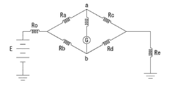
絶縁不良箇所(Fp)の位置を標定する装置の等価回路は図6に示すブリッジ回路となる。この図において、Eは標定用直流電圧源の電圧、Lは事故発生ケーブル及び健全ケーブルの一端から他端までの長さ、lは事故発生ケーブルの一端から絶縁不良箇所までの長さ、Raは測定辺抵抗の摺動接点より健全ケーブル寄りの抵抗値、Rbは測定辺抵抗の摺動接点より事故発生ケーブル寄りの抵抗値、Rcは健全ケーブルの一端から絶縁不良箇所までの導体及び短絡線の抵抗値、Rdは事故発生ケーブルの一端から絶縁不良箇所までの導体の抵抗値、Reは絶縁不良箇所の抵抗値(以下、「地絡抵抗」という。)、Rgは検流計メータの内部抵抗値、Roは標定用直流電圧源の内部抵抗値を示す記号である。 An equivalent circuit of the device for locating the position of the insulation failure point (Fp) is a bridge circuit shown in FIG. In this figure, E is the voltage of the DC voltage source for orientation, L is the length from one end to the other end of the accident occurrence cable and the sound cable, l is the length from one end of the accident occurrence cable to the location of poor insulation, and Ra is Rb is the resistance value closer to the sound cable than the sliding contact of the measurement side resistance, Rb is the resistance value closer to the cable where the accident occurred than the sliding contact of the measurement side resistance, and Rc is the conductor and short-circuit line from one end of the healthy cable to the location of poor insulation The resistance value, Rd is the resistance value of the conductor from one end of the cable where the accident occurred to the poor insulation location, Re is the resistance value of the poor insulation location (hereinafter referred to as “ground fault resistance”), and Rg is the internal resistance of the galvanometer meter. The value Ro is a symbol indicating the internal resistance value of the DC voltage source for orientation.
この等価回路で、測定辺抵抗の摺動接点を動かして測定辺抵抗の按分位置を変化させ、検流計メータに流れる電流を零に調整した場合、Ra×Rd=Rb×Rcが成立する。
ここで、健全ケーブル及び事故発生ケーブルの導体の単位長さ当たりの抵抗値をρとしたとき、Rc=ρ×(2L−l)及びRd=ρ×Lとなるので、Ra×Rd=Rb×Rcにこれらの関係を代入して整理すると、l=L×2×Rb/(Ra+Rb)となる。
そして、Lは事故発生ケーブル又は健全ケーブルの一端から他端までの長さを計測して知り得る値、Rbは測定辺抵抗の按分位置から知り得る値、Ra+Rbは一定値であるので、lすなわち事故発生ケーブルの一端から絶縁不良箇所までの長さが分かり、絶縁不良箇所(Fp)の位置を標定できる。
In this equivalent circuit, when the apportioning position of the measurement side resistance is changed by moving the sliding contact of the measurement side resistance and the current flowing through the galvanometer meter is adjusted to zero, Ra × Rd = Rb × Rc is established.
Here, when the resistance value per unit length of the conductor of the sound cable and the cable having the accident is ρ, Rc = ρ × (2L−1) and Rd = ρ × L, so Ra × Rd = Rb × Substituting these relationships into Rc and rearranging results in l = L × 2 × Rb / (Ra + Rb).
L is a value that can be obtained by measuring the length from one end to the other end of the accident-occurring cable or the healthy cable, Rb is a value that can be obtained from the prorated position of the measured side resistance, and Ra + Rb is a constant value. The length from one end of the cable where the accident occurred to the insulation failure location is known, and the location of the insulation failure location (Fp) can be determined.
ところが、地絡抵抗(Re)が高い場合、図6のブリッジ回路では地絡抵抗(Re)での電圧降下が大きくなる上に、電力ケーブルの導体抵抗が小さい(0.02〜0.08Ω/km)ことから、検流計メータ(G)の両端における電位差が非常に小さくなってしまい、絶縁不良箇所の標定は不可能であった。そのため従来、地絡抵抗が高い場合には、高電圧課電による焼成で絶縁不良箇所を低抵抗にして標定していた。
そして、高抵抗の絶縁不良は電力ケーブルの端末部や接続部で発生する場合も多いところ、高電圧課電による焼成を行った場合、焼成の対象となった電力ケーブルは損傷を受ける可能性があるため、電力ケーブル自体には絶縁不良箇所が発生していないにもかかわらず、標定後にその電力ケーブルを交換していた。
However, when the ground fault resistance (Re) is high, the voltage drop at the ground fault resistance (Re) increases in the bridge circuit of FIG. 6 and the conductor resistance of the power cable is low (0.02 to 0.08 Ω / km), the potential difference between both ends of the galvanometer meter (G) becomes very small, and it is impossible to determine the location of the insulation failure. For this reason, conventionally, when the ground fault resistance is high, the insulation failure location is reduced to a low resistance by firing by high voltage application.
In many cases, high-resistance insulation failures occur at the ends and connections of power cables. When firing by high-voltage power, the fired power cables may be damaged. For this reason, the power cable itself was replaced after standardization even though there was no defective insulation in the power cable itself.
そこで、特許文献1(特開2006−267002号公報)に記載されるように、高電圧課電による焼成を避けるために、従来の標定装置の検出感度を大幅に向上させ、標定範囲を10倍程度拡大させた新型の標定装置が開発された。この標定装置によれば、ケーブル導体の断面積が150mm2(直径13.8mm)、測定される電力ケーブルの長さ(以下、「亘長」という。)が1000mの場合、地絡抵抗が200MΩ程度までであれば、絶縁不良箇所の位置を標定可能である。
しかし、最近は送電容量の大容量化に伴ってケーブル導体の断面積は大きくなっており、325mm2(直径20.3mm)、さらには725mm2(直径30.4mm)のものが用いられるようになっているところ、標定可能な地絡抵抗は、ケーブル導体の単位長さ当たりの抵抗値及び亘長に比例し、現場における標定の際の亘長は100m程度の場合もあるため、新型の標定装置を用いたとしても、標定可能な地絡抵抗は、断面積150mm2、亘長100mの場合20MΩ(200MΩ×0.1)、断面積325mm2、亘長100mの場合9.2MΩ(200MΩ×150÷325×0.1)となり、断面積725mm2、亘長100mの場合4.1MΩ(200MΩ×150÷725×0.1)に過ぎない。
そして、地絡抵抗は200MΩ程度となる場合も多いため、標定能力を通常の標定装置の100倍から500倍(新型の標定装置の10倍から50倍)に拡大することが、絶縁不良箇所標定の現場において強く求められている。
Therefore, as described in Patent Document 1 (Japanese Patent Laid-Open No. 2006-267002), in order to avoid firing due to high voltage application, the detection sensitivity of the conventional orientation device is greatly improved, and the orientation range is increased by 10 times. A new type of orientation device has been developed. According to this orientation apparatus, when the cross-sectional area of the cable conductor is 150 mm 2 (diameter 13.8 mm), and the length of the power cable to be measured (hereinafter referred to as “cross length”) is 1000 m, the ground fault resistance is 200 MΩ. If it is to the extent, the position of the insulation failure location can be determined.
However, recently the cross-sectional area of the cable conductor with the capacity of transmission capacity is larger, 325 mm 2 (diameter 20.3 mm), more so is used as a 725 mm 2 (diameter 30.4 mm) Therefore, the ground fault resistance that can be determined is proportional to the resistance value per unit length of the cable conductor and the length of the cable conductor, and the length at the time of standardization in the field may be about 100 m. Even if the apparatus is used, the ground fault resistance that can be determined is 20 MΩ (200 MΩ × 0.1) when the cross-sectional area is 150 mm 2 and the total length is 100 m, 9.2 MΩ (200 MΩ × when the cross-sectional area is 325 mm 2 and the total length is 100 m. 150 ÷ 325 × 0.1), and when the cross-sectional area is 725 mm 2 and the span length is 100 m, it is only 4.1 MΩ (200 MΩ × 150 ÷ 725 × 0.1).
And since the ground fault resistance is often about 200 MΩ, it is possible to increase the location ability from 100 times to 500 times that of a normal orientation device (10 times to 50 times that of a new orientation device). Is strongly demanded in the field.
本発明の課題は、亘長が短くても電力ケーブルを焼成せずに絶縁不良箇所を標定できるようにすること、ケーブルサイズが大きくても電力ケーブルを焼成せずに絶縁不良箇所を標定できるようにすること及び標定誤差をできるだけ小さくすることである。 It is an object of the present invention to be able to determine an insulation failure location without firing the power cable even if the span is short, and to be able to identify the insulation failure location without firing the power cable even if the cable size is large. And making the orientation error as small as possible.
請求項1に係る発明の電力ケーブル高抵抗絶縁不良箇所標定方法は、検流計メータ及び測定辺抵抗を、事故発生ケーブルの遮蔽層の一端と健全ケーブルの遮蔽層の一端との間に並列に接続し、一部に可変抵抗を含む測定辺抵抗の所定の接点又は測定辺抵抗の按分位置を変化させることが可能な摺動接点と接地点との間に標定用直流電圧を印加し、前記事故発生ケーブルの遮蔽層の他端と前記健全ケーブルの遮蔽層の他端を短絡線で接続するとともに、前記事故発生ケーブルの導体を接地してブリッジ回路を形成し、前記測定辺抵抗の一部の抵抗値を変化させるか、前記測定辺抵抗の按分位置を変化させることによって、前記検流計メータに流れる電流を零に調整し、前記測定辺抵抗の一部の抵抗値又は前記測定辺抵抗の按分位置に基づいて電力ケーブルの絶縁不良箇所の位置を標定することを特徴とする。 In the power cable high resistance insulation failure location method according to the first aspect of the invention, the galvanometer meter and the measurement side resistance are arranged in parallel between one end of the shielding layer of the accident cable and one end of the shielding layer of the sound cable. Connecting, applying a DC voltage for orientation between a predetermined contact of the measurement side resistance including a variable resistance in part or a sliding contact capable of changing a prorated position of the measurement side resistance and the grounding point, Connect the other end of the shielding layer of the accident cable to the other end of the shielding layer of the sound cable with a short-circuit wire, and ground the conductor of the accident cable to form a bridge circuit. The resistance value of the measurement side resistance is changed or the apportioning position of the measurement side resistance is changed to adjust the current flowing through the galvanometer meter to zero, and the resistance value of a part of the measurement side resistance or the measurement side resistance Based on the apportionment position of Characterized by locating the position of the insulation failure portion of the cable.
請求項2に係る発明の電力ケーブル高抵抗絶縁不良箇所標定方法は、請求項1に記載の電力ケーブル高抵抗絶縁不良箇所標定方法において、前記標定用直流電圧を前記電力ケーブルに接続される開閉装置の許容直流電圧値以下の電圧とするとともに、前記検流計メータと、前記事故発生ケーブルの遮蔽層の一端及び前記健全ケーブルの遮蔽層の一端との間に、前記電力ケーブルに重畳するノイズが前記検流計メータに入力されることを防止するノイズ防止回路を接続することを特徴とする。
The power cable high resistance insulation failure location determination method according to
請求項3に係る発明の電力ケーブル高抵抗絶縁不良箇所標定方法は、請求項1又は2に記載の電力ケーブル高抵抗絶縁不良箇所標定方法において、前記事故発生ケーブルにおける検流計メータ及び測定辺抵抗の接続点に対する一端側近傍の周囲に、前記事故発生ケーブルの導体及び遮蔽層とは絶縁された導電性の第1高圧ガードを配置し、前記事故発生ケーブルにおける短絡線の接続点に対する他端側近傍の周囲に、前記事故発生ケーブルの導体及び遮蔽層とは絶縁された導電性の第2高圧ガードを配置し、前記第1高圧ガード及び第2高圧ガードを電気的に接続するとともに、前記第1高圧ガード及び第2高圧ガードに前記標定用直流電圧程度の直流電圧を印加することを特徴とする。
The power cable high resistance insulation failure location determination method of the invention according to
請求項4に係る発明の電力ケーブル高抵抗絶縁不良箇所標定方法は、請求項1又は2に記載の電力ケーブル高抵抗絶縁不良箇所標定方法において、前記事故発生ケーブルにおける検流計メータ及び測定辺抵抗の接続点に対する一端側近傍の周囲に、前記事故発生ケーブルの導体及び遮蔽層とは絶縁された導電性の第1高圧ガードを配置し、前記事故発生ケーブルにおける短絡線の接続点に対する他端側近傍の周囲に、前記事故発生ケーブルの導体及び遮蔽層とは絶縁された導電性の第2高圧ガードを配置し、前記事故発生ケーブルにおける検流計メータ及び測定辺抵抗の接続点に対する他端側近傍の周囲に、前記事故発生ケーブルの導体及び遮蔽層とは絶縁された導電性の第3高圧ガードを配置し、前記事故発生ケーブルにおける短絡線の接続点に対する一端側近傍の周囲に、前記事故発生ケーブルの導体及び遮蔽層とは絶縁された導電性の第4高圧ガードを配置し、前記健全ケーブルにおける検流計メータ及び測定辺抵抗の接続点に対する他端側近傍の周囲に、前記健全ケーブルの導体及び遮蔽層とは絶縁された導電性の第5高圧ガードを配置し、前記健全ケーブルにおける短絡線の接続点に対する一端側近傍の周囲に、前記健全ケーブルの導体及び遮蔽層とは絶縁された導電性の第6高圧ガードを配置し、前記第1高圧ガードないし前記第6高圧ガードを電気的に接続するとともに、前記第1高圧ガードないし前記第6高圧ガードに前記標定用直流電圧程度の直流電圧を印加することを特徴とする。 The power cable high resistance insulation failure location determination method of the invention according to claim 4 is the power cable high resistance insulation failure location determination method according to claim 1 or 2, wherein the galvanometer meter and the measurement side resistance in the accident occurrence cable. A conductive first high-voltage guard insulated from the conductor and shielding layer of the accident occurrence cable is disposed around the vicinity of one end side with respect to the connection point, and the other end side with respect to the connection point of the short-circuit line in the accident occurrence cable A conductive second high voltage guard insulated from the conductor and shielding layer of the accident occurrence cable is disposed around the vicinity, and the other end side of the accident occurrence cable with respect to the connection point of the galvanometer meter and the measurement side resistance A conductive third high-voltage guard insulated from the conductor and shielding layer of the accident occurrence cable is arranged around the vicinity, and a short-circuit wire is connected to the accident occurrence cable. A conductive fourth high-voltage guard insulated from the conductor and shielding layer of the accident cable is arranged around one end side of the point, and is connected to the connection point of the galvanometer meter and the measurement side resistance in the healthy cable. Around the vicinity of the other end side, a conductive fifth high voltage guard insulated from the conductor and shielding layer of the healthy cable is disposed, and around the one end side to the connection point of the short-circuit line in the healthy cable, A conductive sixth high voltage guard insulated from a conductor and a shielding layer of the healthy cable is disposed, and the first high voltage guard to the sixth high voltage guard are electrically connected to each other, and the first high voltage guard to the first high voltage guard to the first high voltage guard. 6 DC voltage about the said DC voltage for an orientation is applied to a high voltage | pressure guard, It is characterized by the above-mentioned.
請求項5に係る発明の電力ケーブル高抵抗絶縁不良箇所標定装置は、事故発生ケーブルの遮蔽層の一端と健全ケーブルの遮蔽層の一端との間に並列に接続される検流計メータ及び測定辺抵抗、一部に可変抵抗を含む測定辺抵抗の所定の接点又は測定辺抵抗の按分位置を変化させることが可能な摺動接点、前記所定の接点又は前記摺動接点と接地点との間に標定用直流電圧を印加する標定用直流電圧源、前記事故発生ケーブルの遮蔽層の他端と前記健全ケーブルの遮蔽層の他端を接続する短絡線、並びに前記事故発生ケーブルの導体と接地点とを接続するアース線を備えることを特徴とする。
The power cable high resistance insulation failure location device of the invention according to
請求項6に係る発明の電力ケーブル高抵抗絶縁不良箇所標定装置は、請求項5に記載の電力ケーブル高抵抗絶縁不良箇所標定装置において、前記標定用直流電圧源の電圧を前記電力ケーブルに接続される開閉装置の許容直流電圧値以下にするとともに、前記検流計メータと前記事故発生ケーブルの遮蔽層の一端及び前記健全ケーブルの遮蔽層の一端との間に接続され、前記電力ケーブルに重畳するノイズが前記検流計メータに入力されることを防止するノイズ侵入防止回路を備えることを特徴とする。
The power cable high resistance insulation failure location determination device according to
請求項7に係る発明の電力ケーブル高抵抗絶縁不良箇所標定装置は、請求項5又は6に記載の電力ケーブル高抵抗絶縁不良箇所標定装置において、前記事故発生ケーブルにおける検流計メータ及び測定辺抵抗の接続点に対する一端側近傍の周囲に、前記事故発生ケーブルの導体及び遮蔽層とは絶縁されて配置される導電性の第1高圧ガード、前記事故発生ケーブルにおける短絡線の接続点に対する他端側近傍の周囲に、前記事故発生ケーブルの導体及び遮蔽層とは絶縁されて配置される導電性の第2高圧ガード、前記第1高圧ガード及び第2高圧ガードを電気的に接続する相互接続線、及び前記第1高圧ガード及び第2高圧ガードに前記標定用直流電圧程度の直流電圧を印加する直流電圧源を備えることを特徴とする。
The power cable high resistance insulation failure location determination device according to
請求項8に係る発明の電力ケーブル高抵抗絶縁不良箇所標定装置は、請求項5又は6に記載の電力ケーブル高抵抗絶縁不良箇所標定装置において、前記事故発生ケーブルにおける検流計メータ及び測定辺抵抗の接続点に対する一端側近傍の周囲に、前記事故発生ケーブルの導体及び遮蔽層とは絶縁されて配置される導電性の第1高圧ガード、前記事故発生ケーブルにおける短絡線の接続点に対する他端側近傍の周囲に、前記事故発生ケーブルの導体及び遮蔽層とは絶縁されて配置される導電性の第2高圧ガード、前記事故発生ケーブルにおける検流計メータ及び測定辺抵抗の接続点に対する他端側近傍の周囲に、前記事故発生ケーブルの導体及び遮蔽層とは絶縁されて配置される導電性の第3高圧ガード、前記事故発生ケーブルにおける短絡線の接続点に対する一端側近傍の周囲に、前記事故発生ケーブルの導体及び遮蔽層とは絶縁されて配置される導電性の第4高圧ガード、前記健全ケーブルにおける検流計メータ及び測定辺抵抗の接続点に対する他端側近傍の周囲に、前記健全ケーブルの導体及び遮蔽層とは絶縁されて配置される導電性の第5高圧ガード、前記健全ケーブルにおける短絡線の接続点に対する一端側近傍の周囲に、前記健全ケーブルの導体及び遮蔽層とは絶縁されて配置される導電性の第6高圧ガード、前記第1高圧ガードないし前記第6高圧ガードを電気的に接続する相互接続線、並びに前記第1高圧ガードないし前記第6高圧ガードに前記標定用直流電圧程度の直流電圧を印加する直流電圧源を備えることを特徴とする。
The power cable high resistance insulation failure location determination device according to
請求項9に係る発明の電力ケーブル高抵抗絶縁不良箇所標定装置は、請求項5又は6に記載の電力ケーブル高抵抗絶縁不良箇所標定装置において、前記事故発生ケーブルにおける検流計メータ及び測定辺抵抗の接続点に対する一端側近傍の周囲に、前記事故発生ケーブルの導体及び遮蔽層とは絶縁されて配置される導電性の第1高圧ガード、前記事故発生ケーブルにおける短絡線の接続点に対する他端側近傍の周囲に、前記事故発生ケーブルの導体及び遮蔽層とは絶縁されて配置される導電性の第2高圧ガード、前記事故発生ケーブルにおける検流計メータ及び測定辺抵抗の接続点に対する他端側近傍の周囲に、前記事故発生ケーブルの導体及び遮蔽層とは絶縁されて配置される導電性の第3高圧ガード、前記事故発生ケーブルにおける短絡線の接続点に対する一端側近傍の周囲に、前記事故発生ケーブルの導体及び遮蔽層とは絶縁されて配置される導電性の第4高圧ガード、前記健全ケーブルにおける検流計メータ及び測定辺抵抗の接続点に対する他端側近傍の周囲に、前記健全ケーブルの導体及び遮蔽層とは絶縁されて配置される導電性の第5高圧ガード、前記健全ケーブルにおける短絡線の接続点に対する一端側近傍の周囲に、前記健全ケーブルの導体及び遮蔽層とは絶縁されて配置される導電性の第6高圧ガード、前記検流計メータ及び前記測定辺抵抗を配置している基板を大地から絶縁し支持する絶縁棒等の絶縁物に、基板及び大地とは絶縁されて配置される導電性の第7高圧ガード、前記第1高圧ガードないし前記第7高圧ガードを電気的に接続する相互接続線、並びに前記第1高圧ガードないし前記第7高圧ガードに前記標定用直流電圧程度の直流電圧を印加する直流電圧源を備えることを特徴とする。
The power cable high resistance insulation failure location determination device according to
請求項2又は6に係る発明によれば、ケーブル導体の断面積が325mm2の場合、ケーブル導体の抵抗値が0.0579Ω/kmであるのに対して、遮蔽層の抵抗値は1.71Ω/kmと29.5倍高くなっているため、標定可能な地絡抵抗は29.5倍、すなわち亘長100mの場合でも271.4MΩ(9.2MΩ×29.5)となり、ケーブル導体の断面積が725mm2の場合、ケーブル導体の抵抗値が0.026Ω/kmであるのに対して、遮蔽層の抵抗値は1.26Ω/kmと48.5倍高くなっているため、標定可能な地絡抵抗は48.5倍、すなわち亘長100mの場合でも198.9MΩ(4.1MΩ×48.5)となって、現場の要求を満足することができる。
According to the invention of
請求項1又は5に係る発明では標定可能な地絡抵抗が上記した値の約10分の1となるため、ケーブル導体の断面積が725mm2の場合、亘長を1000m(標定可能な地絡抵抗198.9MΩ)、ケーブル導体の断面積が325mm2の場合、亘長を700m(標定可能な地絡抵抗190.0MΩ=27.14MΩ×7)程度とる必要があるが、電力ケーブルの焼成を行う必要のない本発明においては、亘長を長くとっても測定誤差が増大する以外には格別の問題が発生しないため十分利用可能である。
In the invention according to
請求項3又は7に係る発明によれば、検流計メータ及び測定辺抵抗が接続される事故発生ケーブルの遮蔽層の一端と事故発生ケーブルの導体、並びに短絡線が接続される事故発生ケーブルの遮蔽層の他端と事故発生ケーブルの導体が近接しているために、請求項1、2、5又は6に係る発明において発生し易い沿面漏洩電流の影響を排除することができるので、請求項1、2、5又は6に係る発明によって絶縁不良箇所の位置を標定する際の標定誤差を小さくすることができるという効果がある。
According to the invention according to
請求項4、8又は9に係る発明によれば、請求項3又は7に係る発明による効果に加えて、シースの外面を伝う沿面漏洩電流の影響を排除することができるため、請求項1、2、5又は6に係る発明によって絶縁不良箇所の位置を標定する際の標定誤差を、より小さくすることができるという効果がある。
そして、請求項3、4、7、8又は9に係る発明による効果は、亘長を長くとった場合には特に重要である。
According to the invention according to
And the effect by the invention which concerns on
請求項1〜9に係る発明によれば、地絡抵抗が高い場合でも高電圧課電による焼成を行うことなく、絶縁不良箇所の位置を標定することができるので、その絶縁不良箇所のみを取り替えるだけで済むため、復旧に要するコストを低減することができる。
特に標定の結果、電力ケーブルの端末部や接続部で絶縁不良が発生していた場合には、その端末部や接続部のみを交換するだけで復旧でき、ケーブル本体の交換が不要となるため、復旧時間と復旧に要するコストを大幅に低減することができる。
さらに、絶縁不良箇所の位置標定に際して操作する装置(測定辺抵抗)には、これまで用いてきたものと同じ方式での標定であり作業者が慣れやすく、これまでの経験で蓄積してきたノウハウを生かせるというメリットもある。
According to the invention which concerns on Claims 1-9, since the position of an insulation defect location can be pinpointed, without performing baking by high voltage application, even when a ground fault resistance is high, only the insulation failure location is replaced. Therefore, the cost required for recovery can be reduced.
In particular, if insulation failure has occurred at the terminal or connection part of the power cable as a result of the orientation, it can be recovered by replacing only the terminal part or connection part, and the cable body need not be replaced. Recovery time and cost required for recovery can be greatly reduced.
In addition, the device (measurement side resistance) that is operated when locating defective insulation locations is standardized using the same method as used so far, making it easy for workers to get used to and know-how accumulated through previous experience. There is also an advantage of being able to make use of it.
以下、実施例によって本発明の実施形態を説明する。 Hereinafter, embodiments of the present invention will be described by way of examples.
[実施例1]
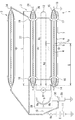
実施例1の電力ケーブル高抵抗絶縁不良箇所標定装置の概念図を図1に示す。
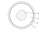
実施例1で標定の対象となる電力ケーブルの断面図は図2に示すような構造であり、中心部から順に、導体4、架橋ポリエチレン等の絶縁体5、銅テープを巻き付けた遮蔽層6、遮水テープ層やビニール被覆層からなるシース7となっている。
実施例1においては、検流計メータ8及び測定辺抵抗9を、事故発生ケーブル1の遮蔽層6の一端と第1の健全ケーブル2の遮蔽層26の一端との間に並列に接続し、測定辺抵抗9の按分位置を変化させることが可能な摺動接点10と接地点との間に標定用直流電圧源11を接続する。
また、遮蔽層6の他端と遮蔽層26の他端を短絡線12で接続するとともに、事故発生ケーブル1の導体4の他端を接地してブリッジ回路を形成している。
[Example 1]
The conceptual diagram of the power cable high resistance insulation defect location apparatus of Example 1 is shown in FIG.
The cross-sectional view of the power cable to be standardized in Example 1 has a structure as shown in FIG. 2, and in order from the center, the conductor 4, the
In the first embodiment, the
In addition, the other end of the
実施例1の接続状態の場合、検流計メータ8及び測定辺抵抗9が接続される遮蔽層6の一端と導体4の一端、及び短絡線12が接続される遮蔽層6の他端と導体4の他端が近接しているとともに、導体4が接地されているため、これらの間で沿面漏洩電流が発生して標定結果に誤差を生じるおそれがあり、さらに、シース7の外面を伝う沿面漏洩電流が発生して標定結果に誤差を生じるおそれもある。
そこで、実施例1においては、遮蔽層6の検流計メータ8及び測定辺抵抗9が接続される点よりも一端側近傍の周囲に、導体4及び遮蔽層6とは絶縁されて配置される導電性の第1高圧ガード14、遮蔽層6の短絡線12が接続される点よりも他端側近傍の周囲に、導体4及び遮蔽層6とは絶縁されて配置される導電性の第2高圧ガード15、遮蔽層6の検流計メータ8及び測定辺抵抗9が接続される点よりも他端側近傍のシース7の周囲に、導体4及び遮蔽層6とは絶縁されて配置される導電性の第3高圧ガード16、遮蔽層6の短絡線12が接続される点よりも一端側近傍のシース7の周囲に、導体4及び遮蔽層6とは絶縁されて配置される導電性の第4高圧ガード17、遮蔽層26の検流計メータ8及び測定辺抵抗9が接続される点よりも他端側近傍のシース27の周囲に、遮蔽層6とは絶縁されて配置される導電性の第5高圧ガード18、遮蔽層26の短絡線12が接続される点よりも一端側近傍のシース7の周囲に、遮蔽層26とは絶縁されて配置される導電性の第6高圧ガード19、並びに検流計メータ8及び測定辺抵抗9を配置している基板28を大地から絶縁し支持する絶縁棒29の周囲に、基板28及び大地とは絶縁されて配置される導電性の第7高圧ガード30を配置し、これら第1〜第7高圧ガード14〜19及び30を相互接続線で電気的に接続するとともに、これらに標定用直流電圧程度の電圧を印加している。
より具体的には、第1高圧ガード14と第3高圧ガード16、第2高圧ガード15と第4高圧ガード17、第3高圧ガード16と第5高圧ガード18、第4高圧ガード17と第6高圧ガード19、第5高圧ガード18と第2の健全ケーブル3の導体34の一端、第5高圧ガード14と摺動接点10、第6高圧ガード19と導体34の他端、第7高圧ガード30と摺動接点10を、それぞれ相互接続線で電気的に接続することにより、第1〜第7高圧ガード14〜19及び30に標定用直流電圧Eとほぼ同じ電圧を印加している。
In the case of the connection state of Example 1, one end of the
Therefore, in the first embodiment, the conductor 4 and the
More specifically, the first
実施例1の電力ケーブル高抵抗絶縁不良箇所標定装置によって、絶縁不良箇所の位置を標定するに際しては、従来の装置によって標定する場合と同様、測定辺抵抗9の摺動接点10を操作して按分位置を変化させ、検流計メータ8に流れる電流を零に調整する。その時の測定辺抵抗9の摺動接点10より事故発生ケーブル1側の抵抗値又は測定辺抵抗9における按分位置を読み取る。
そして、実施例1の等価回路は、RcとRdが異なるだけで従来の装置における等価回路と何ら変わるものではないので、上記背景技術の項で説明したと同様、l=L×2×Rb/(Ra+Rb)を計算することにより、lすなわち事故発生ケーブル1の一端から絶縁不良箇所Fpまでの長さが分かり、絶縁不良箇所Fpの位置を標定できる。
When the position of the insulation failure location is determined by the power cable high resistance insulation failure location device of Example 1, the sliding
The equivalent circuit of the first embodiment is not different from the equivalent circuit in the conventional apparatus except that Rc and Rd are different. Therefore, as described in the background section above, l = L × 2 × Rb / By calculating (Ra + Rb), it is possible to know l, that is, the length from one end of the
[実施例2]
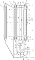
実施例2の電力ケーブル高抵抗絶縁不良箇所標定装置の概念図を図3に示す。
実施例2は、検流計メータ8が遮蔽層6の一端及び遮蔽層26の一端と直接接続されていない点と補助装置が追加されている点を除き、図1に示した実施例1の電力ケーブル高抵抗絶縁不良箇所標定装置と基本的な構成は同じである。
そして、実施例1との相違点は、ノイズ侵入防止回路20を、測定辺抵抗9と並列に、遮蔽層6の一端と遮蔽層26の一端との間に接続するとともに、検流計メータ8をノイズ侵入防止回路20に接続している点、摺動接点10が測定辺抵抗9を按分している位置を検出し、按分比率を演算して表示する比率演算部21及び按分比率表示器22を備えている点、並びにノイズ侵入防止回路20及び比率演算部21に電力を供給するバッテリー23を備えている点である。
実施例1と実施例2との具体的な構成の相違については、特許文献1(特開2006−267002号公報)の図1、図2、段落0019〜0028及び段落0035〜0037に記載されているとおりであるので詳述は避けるが、高感度で絶縁不良箇所の位置を標定できるように以下のような工夫を施している。
[Example 2]
The conceptual diagram of the power cable high resistance insulation defect location apparatus of Example 2 is shown in FIG.
Example 2 is the same as Example 1 shown in FIG. 1 except that the
The difference from the first embodiment is that the noise
The specific difference between Example 1 and Example 2 is described in FIG. 1, FIG. 2, paragraphs 0019 to 0028, and paragraphs 0035 to 0037 of Patent Document 1 (Japanese Patent Laid-Open No. 2006-267002). Although not described in detail, the following measures are taken so that the position of the insulation failure location can be determined with high sensitivity.
(1)標定用直流電圧源11の電圧を、電力ケーブルに接続される開閉装置の許容直流電圧値以下にするとともに、内部抵抗が低抵抗の直流安定化電源を採用したこと。
(2)ノイズ侵入防止回路20を設けて、電力ケーブルに重畳するノイズが検流計メータ8に入力されることを防止するようにしたこと。
(3)ノイズ侵入防止回路20、検流計メータ8、摺動接点10、比率演算部21、按分比率表示器22、バッテリー23等の絶縁性能を向上させるとともに、検流計メータ8や摺動接点10の操作部(操作スイッチ、操作ダイアル、操作つまみ等)の絶縁性能を向上させ、接地点と所定の絶縁強度を保ち漏れ電流を小さくしたこと。
(1) The voltage of the DC voltage source for
(2) The noise
(3) Improve the insulation performance of the noise
このうち、高感度で絶縁不良箇所を標定するために最低限必要な構成は標定用直流電圧源11の電圧を電力ケーブルに接続される開閉装置の許容直流電圧値以下とする点、及びノイズ侵入防止回路20を設けて、電力ケーブルに重畳するノイズが検流計メータ8に入力されることを防止する点である。
Among these, the minimum configuration necessary for locating a poorly insulated portion with high sensitivity is that the voltage of the locating
実施例2の電力ケーブル高抵抗絶縁不良箇所標定方法及び装置によって、絶縁不良箇所を標定するに際しての操作は、実施例1の場合と全く同じである。
また、実施例2においては、按分比率表示器22に測定辺抵抗9の按分比率、すなわち2×Rb/(Ra+Rb)が表示されるので、L×按分比率の計算だけで、lすなわち事故発生ケーブル1の一端から絶縁不良箇所Fpまでの長さが分かり、簡単に絶縁不良箇所Fpの位置を標定できる。
The operation for locating the insulation failure location by the power cable high resistance insulation failure location method and apparatus of the second embodiment is exactly the same as that of the first embodiment.
In the second embodiment, since the proportional
[参考例]
実施例1、2においては、検流計メータ8及び測定辺抵抗9を、事故発生ケーブル1の遮蔽層6の一端と第1の健全ケーブル2の遮蔽層26の一端との間に並列に接続し、また、遮蔽層6の他端と遮蔽層26の他端を短絡線12で接続するとともに、事故発生ケーブル1の導体4の他端を接地してブリッジ回路を形成しているが、従来の導体課電方式において、複数の高圧ガードを設けることによっても、発生し易い沿面漏洩電流の影響を排除できる電力ケーブル高抵抗絶縁不良箇所標定装置を構成できる。
[Reference example]
In the first and second embodiments, the
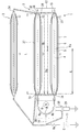
図4は参考例の導体課電方式による電力ケーブル高抵抗絶縁不良箇所標定装置の概念図である。
この電力ケーブル高抵抗絶縁不良箇所標定装置は、事故発生ケーブル1の導体4の一端と健全ケーブル2の導体24の一端との間に並列に接続される検流計メータ8及び測定辺抵抗9、一部に可変抵抗を含む測定辺抵抗9の所定の接点又は測定辺抵抗9の按分位置を変化させることが可能な摺動接点10、所定の接点又は摺動接点10と接地点との間に標定用直流電圧Eを印加する標定用直流電圧源11、事故発生ケーブル1の導体4の他端と健全ケーブル2の導体24の他端を接続する短絡線12、並びに事故発生ケーブル1の遮蔽層6と接地点とを接続するアース線33を備え、事故発生ケーブル1における検流計メータ8及び測定辺抵抗9の接続点に対する他端側近傍の周囲に、事故発生ケーブル1の導体4及び遮蔽層6とは絶縁されて配置される導電性の第1高圧ガード14、事故発生ケーブル1における短絡線12の接続点に対する一端側近傍の周囲に、事故発生ケーブル1の導体4及び遮蔽層6とは絶縁されて配置される導電性の第2高圧ガード15、検流計メータ8及び測定辺抵抗9を配置している基板28を大地から絶縁し支持する絶縁棒29の周囲に、基板28及び大地とは絶縁されて配置される導電性の第7高圧ガード30、健全ケーブル2における検流計メータ8及び測定辺抵抗9の接続点に対する他端側近傍の周囲に、健全ケーブル2の導体24及び遮蔽層26とは絶縁されて配置される導電性の第8高圧ガード31、健全ケーブル2における短絡線12の接続点に対する一端側近傍の周囲に、健全ケーブル2の導体24及び遮蔽層26とは絶縁されて配置される導電性の第9高圧ガード32を配置し、第1高圧ガード14、第2高圧ガード15、第7高圧ガード30、第8高圧ガード31及び第9高圧ガード32を相互接続線で電気的に接続するとともに、これらに標定用直流電圧程度の電圧を印加している。
より具体的には、第1高圧ガード14と第8高圧ガード31、第2高圧ガード15と第9高圧ガード32、第8高圧ガード31と第2の健全ケーブル3の導体34の一端、第9高圧ガード32と導体34の他端、第7高圧ガード30と摺動接点10を、それぞれ相互接続線で電気的に接続することにより、第1高圧ガード14、第2高圧ガード15、第7高圧ガード30、第8高圧ガード31及び第9高圧ガード32に標定用直流電圧Eとほぼ同じ電圧を印加している。
FIG. 4 is a conceptual diagram of a power cable high resistance insulation failure location apparatus according to a conductor voltage application method of a reference example.
This power cable high resistance insulation fault location device has a
More specifically, the first high-
参考例の電力ケーブル高抵抗絶縁不良箇所標定装置によって、絶縁不良箇所の位置を標定するに際しても、実施例1及び2によって標定する場合と同様、測定辺抵抗9の摺動接点10を操作して按分位置を変化させ、検流計メータ8に流れる電流を零に調整する。その時の測定辺抵抗9の摺動接点10より事故発生ケーブル1側の抵抗値又は測定辺抵抗9における按分位置を読み取る。
そして、上記背景技術の項で説明したと同様、l=L×2×Rb/(Ra+Rb)を計算することにより、lすなわち事故発生ケーブル1の一端から絶縁不良箇所Fpまでの長さが分かり、絶縁不良箇所Fpの位置を標定できる。
When the location of the insulation failure location is determined by the power cable high resistance insulation failure location device of the reference example, the sliding
Then, as described in the background section above, by calculating l = L × 2 × Rb / (Ra + Rb), it is possible to know the length from l, that is, one end of the
参考例の電力ケーブル高抵抗絶縁不良箇所標定装置によれば、導体課電方式であるにもかかわらず、地絡抵抗が高くかつシース抵抗が低い場合でも高電圧課電による焼成を行うことなく、絶縁不良箇所の位置を標定することができ、その絶縁不良箇所のみを取り替えるだけで済むため、復旧に要するコストを低減することができる。 According to the power cable high resistance insulation fault location device of the reference example, even though it is a conductor charging method, even if the ground fault resistance is high and the sheath resistance is low, without firing by high voltage charging, Since the location of the insulation failure location can be determined and only the insulation failure location needs to be replaced, the cost required for recovery can be reduced.
さらに、参考例を実施例2と同様に、ノイズ侵入防止回路20を、測定辺抵抗9と並列に、遮蔽層6の一端と遮蔽層26の一端との間に接続し、検流計メータ8をノイズ侵入防止回路20に接続するとともに、摺動接点10が測定辺抵抗9を按分している位置を検出し、按分比率を演算して表示する比率演算部21及び按分比率表示器22、並びにノイズ侵入防止回路20及び比率演算部21に電力を供給するバッテリー23を備えるようにすれば、より高抵抗の絶縁不良箇所の位置を標定できるようになる。
Further, similarly to the second embodiment, the noise
なお、参考例では、第1高圧ガード14、第2高圧ガード15、第7高圧ガード30、第8高圧ガード31及び第9高圧ガード32を設置したが、このうち、第1高圧ガード14、第2高圧ガード15、第8高圧ガード31及び第9高圧ガード32は、標定精度を向上するために特に重要である。
In the reference example, the first high-
実施例1、2及び参考例の変形例を列記する。
(1)実施例1、2及び参考例においては、測定辺抵抗9の按分位置を変化させることが可能な摺動接点10を採用したが、測定辺抵抗を可変抵抗Raと固定抵抗Rbを直列に接続したもの又は固定抵抗Raと可変抵抗Rbを直列に接続したものとし、可変抵抗と固定抵抗との間に標定用直流電圧を印加する接点を設けても良い。
その場合、Ra又はRbが変化し、同時にRa+Rbも変化することとなるが、RaとRbを確定できれば、2×Rb/(Ra+Rb)は計算できるので、lを求めることができることに変わりはない。
(2)実施例1及び2においては、第5高圧ガード18と第2の健全ケーブル3の導体34の一端及び第6高圧ガード19と導体34の他端を、それぞれ相互接続線で電気的に接続したが、第5高圧ガード18と第1の健全ケーブル2の導体24の一端及び第6高圧ガード19と導体24の他端を、それぞれ相互接続線で電気的に接続しても良いし、導体34や導体24を利用せずに直接第5高圧ガード18と第6高圧ガード19を相互接続線で接続しても良い。ただし、この場合は別途健全な高圧ケーブルが必要となるため不利である。
(3)実施例1及び2においては、検流計メータ8及び測定辺抵抗9を、事故発生ケーブル1の遮蔽層6の一端と第1の健全ケーブル2の遮蔽層26の一端との間に並列に接続しているが、第1の健全ケーブル2については遮蔽層26に代えて導体24としても、検出可能な地絡抵抗は低下するものの標定は可能である。
(4)実施例1及び2においては、第5高圧ガード14と摺動接点10を相互接続線で接続し、また、参考例においては、第8高圧ガード31と摺動接点10を相互接続線で接続し、標定用直流電圧源11を流用して標定用直流電圧Eとほぼ同じ電圧を印加したが、標定用直流電圧源11を流用せずに標定用直流電圧程度の電圧を印加できる専用の直流電圧源といずれかの高圧ガードを相互接続線で接続しても良い。
(5)実施例2においては、按分比率を演算して表示する比率演算部21及び按分比率表示器22を採用したが、比率演算部21に亘長を入力できる入力部を追加して、L×2×Rb/(Ra+Rb)を演算して表示する位置演算部及び絶縁不良箇所位置表示器とすれば、作業時の計算間違い等を防止でき、確実に事故発生ケーブル1の一端から絶縁不良箇所Fpまでの長さを標定できる。
Examples 1 and 2 and modifications of the reference example are listed.
(1) In the first and second embodiments and the reference example, the sliding
In that case, Ra or Rb changes, and Ra + Rb also changes at the same time. However, if Ra and Rb can be determined, 2 × Rb / (Ra + Rb) can be calculated, so that l can be obtained.
(2) In
(3) In the first and second embodiments, the
(4) In Examples 1 and 2, the fifth high-
(5) In the second embodiment, the
1 事故発生ケーブル 2 第1の健全ケーブル 3 第2の健全ケーブル
4、24、34 導体 5 絶縁体 6、26 遮蔽層
7、27 シース 8 検流計メータ 9 測定辺抵抗 10 摺動接点
11 標定用直流電圧源 12 短絡線 13、33 アース線
14 第1高圧ガード 15 第2高圧ガード 16 第3高圧ガード
17 第4高圧ガード 18 第5高圧ガード 19 第6高圧ガード
20 ノイズ侵入防止回路 21 比率演算部 22 按分比率表示器
23 バッテリー 28 基板 29 絶縁棒 30 第7高圧ガード
31 第8高圧ガード 32 第9高圧ガード
DESCRIPTION OF
Claims (9)
一部に可変抵抗を含む測定辺抵抗の所定の接点又は測定辺抵抗の按分位置を変化させることが可能な摺動接点と接地点との間に標定用直流電圧を印加し、
前記事故発生ケーブルの遮蔽層の他端と前記健全ケーブルの遮蔽層の他端を短絡線で接続するとともに、
前記事故発生ケーブルの導体を接地してブリッジ回路を形成し、
前記測定辺抵抗の一部の抵抗値を変化させるか、前記測定辺抵抗の按分位置を変化させることによって、前記検流計メータに流れる電流を零に調整し、前記測定辺抵抗の一部の抵抗値又は前記測定辺抵抗の按分位置に基づいて電力ケーブルの絶縁不良箇所の位置を標定することを特徴とする
電力ケーブル高抵抗絶縁不良箇所標定方法。 Connect the galvanometer meter and the measurement side resistance in parallel between one end of the shielding layer of the accident cable and one end of the shielding layer of the sound cable,
Apply a DC voltage for orientation between a predetermined contact of the measurement side resistance including a variable resistance or a sliding contact that can change the prorated position of the measurement side resistance and the grounding point,
While connecting the other end of the shielding layer of the accident cable and the other end of the shielding layer of the sound cable with a short-circuit wire,
Grounding the conductor of the accident occurrence cable to form a bridge circuit,
By changing the resistance value of a part of the measurement side resistance or changing the prorated position of the measurement side resistance, the current flowing through the galvanometer meter is adjusted to zero, and a part of the measurement side resistance is adjusted. A power cable high resistance insulation failure location determination method characterized in that the location of an insulation failure location of a power cable is determined based on a resistance value or an apportioned position of the measurement side resistance.
前記検流計メータと、前記事故発生ケーブルの遮蔽層の一端及び前記健全ケーブルの遮蔽層の一端との間に、前記電力ケーブルに重畳するノイズが前記検流計メータに入力されることを防止するノイズ防止回路を接続することを特徴とする
請求項1に記載の電力ケーブル高抵抗絶縁不良箇所標定方法。 The orientation DC voltage is set to a voltage equal to or lower than an allowable DC voltage value of a switchgear connected to the power cable,
Prevents noise superimposed on the power cable from being input to the galvanometer meter between the galvanometer meter and one end of the shielding layer of the accident cable and one end of the shielding layer of the sound cable. A power cable high resistance insulation failure location method according to claim 1, wherein a noise prevention circuit is connected.
前記事故発生ケーブルにおける短絡線の接続点に対する他端側近傍の周囲に、前記事故発生ケーブルの導体及び遮蔽層とは絶縁された導電性の第2高圧ガードを配置し、
前記第1高圧ガード及び第2高圧ガードを電気的に接続するとともに、
前記第1高圧ガード及び第2高圧ガードに前記標定用直流電圧程度の直流電圧を印加する
ことを特徴とする請求項1又は2に記載の電力ケーブル高抵抗絶縁不良箇所標定方法。 A conductive first high-voltage guard insulated from the conductor and shielding layer of the accident occurrence cable is disposed around the vicinity of one end side with respect to the connection point of the galvanometer meter and the measurement side resistance in the accident occurrence cable,
Around the vicinity of the other end side of the connection point of the short-circuit line in the accident occurrence cable, a conductive second high-voltage guard insulated from the conductor and the shielding layer of the accident occurrence cable is disposed,
Electrically connecting the first high pressure guard and the second high pressure guard;
3. The power cable high resistance insulation failure location method according to claim 1, wherein a direct current voltage about the orientation direct current voltage is applied to the first high voltage guard and the second high voltage guard.
前記事故発生ケーブルにおける短絡線の接続点に対する他端側近傍の周囲に、前記事故発生ケーブルの導体及び遮蔽層とは絶縁された導電性の第2高圧ガードを配置し、
前記事故発生ケーブルにおける検流計メータ及び測定辺抵抗の接続点に対する他端側近傍の周囲に、前記事故発生ケーブルの導体及び遮蔽層とは絶縁された導電性の第3高圧ガードを配置し、
前記事故発生ケーブルにおける短絡線の接続点に対する一端側近傍の周囲に、前記事故発生ケーブルの導体及び遮蔽層とは絶縁された導電性の第4高圧ガードを配置し、
前記健全ケーブルにおける検流計メータ及び測定辺抵抗の接続点に対する他端側近傍の周囲に、前記健全ケーブルの導体及び遮蔽層とは絶縁された導電性の第5高圧ガードを配置し、
前記健全ケーブルにおける短絡線の接続点に対する一端側近傍の周囲に、前記健全ケーブルの導体及び遮蔽層とは絶縁された導電性の第6高圧ガードを配置し、
前記第1高圧ガードないし前記第6高圧ガードを電気的に接続するとともに、
前記第1高圧ガードないし前記第6高圧ガードに前記標定用直流電圧程度の直流電圧を印加する
ことを特徴とする請求項1又は2に記載の電力ケーブル高抵抗絶縁不良箇所標定方法。 A conductive first high-voltage guard insulated from the conductor and shielding layer of the accident occurrence cable is disposed around the vicinity of one end side with respect to the connection point of the galvanometer meter and the measurement side resistance in the accident occurrence cable,
Around the vicinity of the other end side of the connection point of the short-circuit line in the accident occurrence cable, a conductive second high-voltage guard insulated from the conductor and the shielding layer of the accident occurrence cable is disposed,
Around the vicinity of the other end side of the connection point of the galvanometer meter and the measurement side resistance in the accident occurrence cable, a conductive third high voltage guard insulated from the conductor and the shielding layer of the accident occurrence cable is disposed,
A conductive fourth high-voltage guard insulated from the conductor and the shielding layer of the accident occurrence cable is disposed around the vicinity of one end side of the connection point of the short-circuit line in the accident occurrence cable,
Around the vicinity of the other end side of the connection point of the galvanometer meter and the measurement side resistance in the sound cable, a conductive fifth high voltage guard insulated from the conductor and the shielding layer of the sound cable is disposed,
A conductive sixth high-voltage guard insulated from the conductor and shielding layer of the healthy cable is disposed around the vicinity of one end side of the connection point of the short-circuit line in the healthy cable,
Electrically connecting the first high pressure guard to the sixth high pressure guard;
3. The power cable high resistance insulation failure location method according to claim 1, wherein a DC voltage that is about the orientation DC voltage is applied to the first high voltage guard to the sixth high voltage guard.
一部に可変抵抗を含む測定辺抵抗の所定の接点又は測定辺抵抗の按分位置を変化させることが可能な摺動接点、
前記所定の接点又は前記摺動接点と接地点との間に標定用直流電圧を印加する標定用直流電圧源、
前記事故発生ケーブルの遮蔽層の他端と前記健全ケーブルの遮蔽層の他端を接続する短絡線、
並びに前記事故発生ケーブルの導体と接地点とを接続するアース線を備える
ことを特徴とする電力ケーブル高抵抗絶縁不良箇所標定装置。 A galvanometer meter and a side resistance connected in parallel between one end of the shield layer of the accident cable and one end of the shield layer of the sound cable;
A predetermined contact of a measuring side resistance including a variable resistance in part or a sliding contact capable of changing a prorated position of the measuring side resistance;
An orientation DC voltage source for applying an orientation DC voltage between the predetermined contact or the sliding contact and a ground point;
A short-circuit wire connecting the other end of the shielding layer of the accident cable and the other end of the shielding layer of the sound cable;
And a grounding wire for connecting a conductor of the accident cable and a grounding point.
前記検流計メータと前記事故発生ケーブルの遮蔽層の一端及び前記健全ケーブルの遮蔽層の一端との間に接続され、前記電力ケーブルに重畳するノイズが前記検流計メータに入力されることを防止するノイズ侵入防止回路を備える
ことを特徴とする請求項5に記載の電力ケーブル高抵抗絶縁不良箇所標定装置。 While making the voltage of the DC voltage source for orientation below the allowable DC voltage value of the switchgear connected to the power cable,
The galvanometer meter is connected between one end of the shielding layer of the accident cable and one end of the shielding layer of the sound cable, and noise superimposed on the power cable is input to the galvanometer meter. A power cable high resistance insulation failure location system according to claim 5, further comprising a noise intrusion prevention circuit for preventing.
前記事故発生ケーブルにおける短絡線の接続点に対する他端側近傍の周囲に、前記事故発生ケーブルの導体及び遮蔽層とは絶縁されて配置される導電性の第2高圧ガード、
前記第1高圧ガード及び第2高圧ガードを電気的に接続する相互接続線、
及び前記第1高圧ガード及び第2高圧ガードに前記標定用直流電圧程度の直流電圧を印加する直流電圧源を備える
ことを特徴とする請求項5又は6に記載の電力ケーブル高抵抗絶縁不良箇所標定装置。 A conductive first high-voltage guard disposed around one end side of a connection point between the galvanometer meter and the measurement side resistance in the accident occurrence cable and insulated from a conductor and a shielding layer of the accident occurrence cable;
A conductive second high-voltage guard disposed around the other end side of the accident occurrence cable in the vicinity of the connection point of the short-circuit line and insulated from the conductor and the shielding layer of the accident occurrence cable;
An interconnection line for electrically connecting the first high voltage guard and the second high voltage guard;
A power cable high resistance insulation fault location according to claim 5 or 6, further comprising a DC voltage source that applies a DC voltage about the DC voltage for orientation to the first high voltage guard and the second high voltage guard. apparatus.
前記事故発生ケーブルにおける短絡線の接続点に対する他端側近傍の周囲に、前記事故発生ケーブルの導体及び遮蔽層とは絶縁されて配置される導電性の第2高圧ガード、
前記事故発生ケーブルにおける検流計メータ及び測定辺抵抗の接続点に対する他端側近傍の周囲に、前記事故発生ケーブルの導体及び遮蔽層とは絶縁されて配置される導電性の第3高圧ガード、
前記事故発生ケーブルにおける短絡線の接続点に対する一端側近傍の周囲に、前記事故発生ケーブルの導体及び遮蔽層とは絶縁されて配置される導電性の第4高圧ガード、
前記健全ケーブルにおける検流計メータ及び測定辺抵抗の接続点に対する他端側近傍の周囲に、前記健全ケーブルの導体及び遮蔽層とは絶縁されて配置される導電性の第5高圧ガード、
前記健全ケーブルにおける短絡線の接続点に対する一端側近傍の周囲に、前記健全ケーブルの導体及び遮蔽層とは絶縁されて配置される導電性の第6高圧ガード、
前記第1高圧ガードないし前記第6高圧ガードを電気的に接続する相互接続線、
並びに前記第1高圧ガードないし前記第6高圧ガードに前記標定用直流電圧程度の直流電圧を印加する直流電圧源を備える
ことを特徴とする請求項5又は6に記載の電力ケーブル高抵抗絶縁不良箇所標定装置。 A conductive first high-voltage guard disposed around one end side of a connection point between the galvanometer meter and the measurement side resistance in the accident occurrence cable and insulated from a conductor and a shielding layer of the accident occurrence cable;
A conductive second high-voltage guard disposed around the other end side of the accident occurrence cable in the vicinity of the connection point of the short-circuit line and insulated from the conductor and the shielding layer of the accident occurrence cable;
A conductive third high-voltage guard disposed around the other end side of the connection point of the galvanometer meter and the measurement side resistance in the accident occurrence cable, insulated from the conductor and the shielding layer of the accident occurrence cable;
A conductive fourth high-voltage guard disposed around the one end side near the connection point of the short-circuit line in the accident occurrence cable and insulated from the conductor and the shielding layer of the accident occurrence cable;
A conductive fifth high-voltage guard disposed around the other end side of the connection point of the galvanometer meter and the measurement side resistance in the sound cable and insulated from the conductor and the shielding layer of the sound cable;
A conductive sixth high-voltage guard disposed around the one end side of the connection point of the short-circuit line in the healthy cable and insulated from the conductor and the shielding layer of the healthy cable;
An interconnection line for electrically connecting the first high-voltage guard to the sixth high-voltage guard;
The power cable high resistance insulation failure location according to claim 5 or 6, further comprising: a DC voltage source that applies a DC voltage of about the DC voltage for orientation to the first high voltage guard to the sixth high voltage guard. Orientation device.
前記事故発生ケーブルにおける短絡線の接続点に対する他端側近傍の周囲に、前記事故発生ケーブルの導体及び遮蔽層とは絶縁されて配置される導電性の第2高圧ガード、
前記事故発生ケーブルにおける検流計メータ及び測定辺抵抗の接続点に対する他端側近傍の周囲に、前記事故発生ケーブルの導体及び遮蔽層とは絶縁されて配置される導電性の第3高圧ガード、
前記事故発生ケーブルにおける短絡線の接続点に対する一端側近傍の周囲に、前記事故発生ケーブルの導体及び遮蔽層とは絶縁されて配置される導電性の第4高圧ガード、
前記健全ケーブルにおける検流計メータ及び測定辺抵抗の接続点に対する他端側近傍の周囲に、前記健全ケーブルの導体及び遮蔽層とは絶縁されて配置される導電性の第5高圧ガード、
前記健全ケーブルにおける短絡線の接続点に対する一端側近傍の周囲に、前記健全ケーブルの導体及び遮蔽層とは絶縁されて配置される導電性の第6高圧ガード、
前記検流計メータ及び前記測定辺抵抗を配置している基板を大地から絶縁し支持する絶縁棒等の絶縁物に、基板及び大地とは絶縁されて配置される導電性の第7高圧ガード、
前記第1高圧ガードないし前記第7高圧ガードを電気的に接続する相互接続線、
並びに前記第1高圧ガードないし前記第7高圧ガードに前記標定用直流電圧程度の直流電圧を印加する直流電圧源を備える
ことを特徴とする請求項5又は6に記載の電力ケーブル高抵抗絶縁不良箇所標定装置。 A conductive first high-voltage guard disposed around one end side of a connection point between the galvanometer meter and the measurement side resistance in the accident occurrence cable and insulated from a conductor and a shielding layer of the accident occurrence cable;
A conductive second high-voltage guard disposed around the other end side of the accident occurrence cable in the vicinity of the connection point of the short-circuit line and insulated from the conductor and the shielding layer of the accident occurrence cable;
A conductive third high-voltage guard disposed around the other end side of the connection point of the galvanometer meter and the measurement side resistance in the accident occurrence cable, insulated from the conductor and the shielding layer of the accident occurrence cable;
A conductive fourth high-voltage guard disposed around the one end side near the connection point of the short-circuit line in the accident occurrence cable and insulated from the conductor and the shielding layer of the accident occurrence cable;
A conductive fifth high-voltage guard disposed around the other end side of the connection point of the galvanometer meter and the measurement side resistance in the sound cable and insulated from the conductor and the shielding layer of the sound cable;
A conductive sixth high-voltage guard disposed around the one end side of the connection point of the short-circuit line in the healthy cable and insulated from the conductor and the shielding layer of the healthy cable;
A conductive seventh high-voltage guard disposed on an insulator such as an insulating rod that insulates and supports the substrate on which the galvanometer meter and the measurement side resistance are disposed from the ground, and is insulated from the substrate;
An interconnection line for electrically connecting the first high-voltage guard to the seventh high-voltage guard;
A power cable high resistance insulation failure location according to claim 5 or 6, further comprising a DC voltage source that applies a DC voltage about the DC voltage for orientation to the first high voltage guard to the seventh high voltage guard. Orientation device.
Priority Applications (1)
| Application Number | Priority Date | Filing Date | Title |
|---|---|---|---|
| JP2013056895A JP6069051B2 (en) | 2013-03-19 | 2013-03-19 | Power cable high resistance insulation failure location method and apparatus |
Applications Claiming Priority (1)
| Application Number | Priority Date | Filing Date | Title |
|---|---|---|---|
| JP2013056895A JP6069051B2 (en) | 2013-03-19 | 2013-03-19 | Power cable high resistance insulation failure location method and apparatus |
Publications (2)
| Publication Number | Publication Date |
|---|---|
| JP2014182014A true JP2014182014A (en) | 2014-09-29 |
| JP6069051B2 JP6069051B2 (en) | 2017-01-25 |
Family
ID=51700864
Family Applications (1)
| Application Number | Title | Priority Date | Filing Date |
|---|---|---|---|
| JP2013056895A Active JP6069051B2 (en) | 2013-03-19 | 2013-03-19 | Power cable high resistance insulation failure location method and apparatus |
Country Status (1)
| Country | Link |
|---|---|
| JP (1) | JP6069051B2 (en) |
Cited By (2)
| Publication number | Priority date | Publication date | Assignee | Title |
|---|---|---|---|---|
| CN109507540A (en) * | 2018-12-20 | 2019-03-22 | 孟小晶 | High value ground short circuit fault point is pressed to search instrument and lookup method in one kind |
| CN111983268A (en) * | 2020-09-27 | 2020-11-24 | 华润电力投资有限公司中西分公司 | A high-voltage power distribution cabinet and its interface device |
Citations (3)
| Publication number | Priority date | Publication date | Assignee | Title |
|---|---|---|---|---|
| JPS5032456A (en) * | 1973-07-28 | 1975-03-29 | ||
| JPH03214073A (en) * | 1990-01-19 | 1991-09-19 | Hitachi Cable Ltd | How to measure DC leakage current of power cables |
| JP2006267002A (en) * | 2005-03-25 | 2006-10-05 | Tokyo Electric Power Co Inc:The | Insulation degradation position evaluation apparatus and method |
-
2013
- 2013-03-19 JP JP2013056895A patent/JP6069051B2/en active Active
Patent Citations (3)
| Publication number | Priority date | Publication date | Assignee | Title |
|---|---|---|---|---|
| JPS5032456A (en) * | 1973-07-28 | 1975-03-29 | ||
| JPH03214073A (en) * | 1990-01-19 | 1991-09-19 | Hitachi Cable Ltd | How to measure DC leakage current of power cables |
| JP2006267002A (en) * | 2005-03-25 | 2006-10-05 | Tokyo Electric Power Co Inc:The | Insulation degradation position evaluation apparatus and method |
Cited By (2)
| Publication number | Priority date | Publication date | Assignee | Title |
|---|---|---|---|---|
| CN109507540A (en) * | 2018-12-20 | 2019-03-22 | 孟小晶 | High value ground short circuit fault point is pressed to search instrument and lookup method in one kind |
| CN111983268A (en) * | 2020-09-27 | 2020-11-24 | 华润电力投资有限公司中西分公司 | A high-voltage power distribution cabinet and its interface device |
Also Published As
| Publication number | Publication date |
|---|---|
| JP6069051B2 (en) | 2017-01-25 |
Similar Documents
| Publication | Publication Date | Title |
|---|---|---|
| US7459914B2 (en) | Systems and methods for electrical leakage detection | |
| US20150088438A1 (en) | Ratio metric current measurement | |
| EP2588871B1 (en) | Apparatus and method for measuring the dissipation factor of an insulator | |
| JP5009950B2 (en) | Test method and apparatus for grounding device | |
| US9529031B2 (en) | Grounding detection device and method | |
| JP6069051B2 (en) | Power cable high resistance insulation failure location method and apparatus | |
| KR101984432B1 (en) | Diagnosis device for monitoring degradation of cable and diagnosis method thereof | |
| JP2011242206A (en) | Insulation deterioration diagnosis method and insulation deterioration diagnosis device of power cable | |
| US8854068B2 (en) | Diagnostic method for oil-filled electrical device, diagnostic device for implementing the diagnostic method, and oil-filled electrical device provided with the diagnostic device | |
| US4410850A (en) | Water-compensated open fault locator | |
| EP4257987B1 (en) | Method for locating a fault point on a high-voltage three-phase ac cable, and system for locating a fault point | |
| JP5510964B2 (en) | Continuity inspection method | |
| JP4984411B2 (en) | Insulation degradation position evaluation apparatus and method | |
| CN108369254A (en) | The method for positioning the failure in power transmission medium | |
| JP2014202696A (en) | Electrical leak detection method | |
| CN215813274U (en) | Breakpoint detection sheath and cable comprising same | |
| CN111190086A (en) | A GIS partial discharge online monitoring device | |
| US2832042A (en) | Fault locating apparatus | |
| KR100852039B1 (en) | Water leakage sensing device of heat piping and its method | |
| JP2020106407A (en) | Device and method for diagnosing deterioration of insulator of connection body for high voltage overhead cable | |
| KR101391146B1 (en) | On-Line Cable Status Monitoring Apparatus and Method thereof | |
| EP2588872B1 (en) | Apparatus and method for measuring the dissipation factor of an insulator | |
| JP4050433B2 (en) | Damage determination apparatus and damage determination method for coated buried metal conductor | |
| CN111913126B (en) | Insulation pad arcing fault detection method | |
| RU2321009C1 (en) | Method and device for measurement of earth rod resistance |
Legal Events
| Date | Code | Title | Description |
|---|---|---|---|
| A621 | Written request for application examination |
Free format text: JAPANESE INTERMEDIATE CODE: A621 Effective date: 20160222 |
|
| A131 | Notification of reasons for refusal |
Free format text: JAPANESE INTERMEDIATE CODE: A131 Effective date: 20160927 |
|
| A521 | Request for written amendment filed |
Free format text: JAPANESE INTERMEDIATE CODE: A523 Effective date: 20161122 |
|
| TRDD | Decision of grant or rejection written | ||
| A01 | Written decision to grant a patent or to grant a registration (utility model) |
Free format text: JAPANESE INTERMEDIATE CODE: A01 Effective date: 20161220 |
|
| A61 | First payment of annual fees (during grant procedure) |
Free format text: JAPANESE INTERMEDIATE CODE: A61 Effective date: 20161226 |
|
| R150 | Certificate of patent or registration of utility model |
Ref document number: 6069051 Country of ref document: JP Free format text: JAPANESE INTERMEDIATE CODE: R150 |
|
| R250 | Receipt of annual fees |
Free format text: JAPANESE INTERMEDIATE CODE: R250 |
|
| S111 | Request for change of ownership or part of ownership |
Free format text: JAPANESE INTERMEDIATE CODE: R313111 |
|
| R350 | Written notification of registration of transfer |
Free format text: JAPANESE INTERMEDIATE CODE: R350 |
|
| R250 | Receipt of annual fees |
Free format text: JAPANESE INTERMEDIATE CODE: R250 |
|
| R250 | Receipt of annual fees |
Free format text: JAPANESE INTERMEDIATE CODE: R250 |
|
| R250 | Receipt of annual fees |
Free format text: JAPANESE INTERMEDIATE CODE: R250 |
|
| R250 | Receipt of annual fees |
Free format text: JAPANESE INTERMEDIATE CODE: R250 |
|
| R250 | Receipt of annual fees |
Free format text: JAPANESE INTERMEDIATE CODE: R250 |
|
| R250 | Receipt of annual fees |
Free format text: JAPANESE INTERMEDIATE CODE: R250 |