JP2014190816A - Spring device for timepiece - Google Patents
Spring device for timepiece Download PDFInfo
- Publication number
- JP2014190816A JP2014190816A JP2013066192A JP2013066192A JP2014190816A JP 2014190816 A JP2014190816 A JP 2014190816A JP 2013066192 A JP2013066192 A JP 2013066192A JP 2013066192 A JP2013066192 A JP 2013066192A JP 2014190816 A JP2014190816 A JP 2014190816A
- Authority
- JP
- Japan
- Prior art keywords
- mainspring
- hole
- slit
- timepiece
- fixing member
- Prior art date
- Legal status (The legal status is an assumption and is not a legal conclusion. Google has not performed a legal analysis and makes no representation as to the accuracy of the status listed.)
- Pending
Links
- 229910052710 silicon Inorganic materials 0.000 claims description 9
- 239000010703 silicon Substances 0.000 claims description 9
- 238000004804 winding Methods 0.000 claims description 7
- 230000002093 peripheral effect Effects 0.000 claims description 5
- 239000000463 material Substances 0.000 abstract description 16
- 230000003213 activating effect Effects 0.000 abstract 1
- 230000035939 shock Effects 0.000 abstract 1
- XUIMIQQOPSSXEZ-UHFFFAOYSA-N Silicon Chemical compound [Si] XUIMIQQOPSSXEZ-UHFFFAOYSA-N 0.000 description 8
- 238000004519 manufacturing process Methods 0.000 description 8
- 238000000034 method Methods 0.000 description 7
- 238000005530 etching Methods 0.000 description 4
- 238000001020 plasma etching Methods 0.000 description 4
- 238000001312 dry etching Methods 0.000 description 3
- 239000002184 metal Substances 0.000 description 3
- 238000005516 engineering process Methods 0.000 description 2
- 229910001220 stainless steel Inorganic materials 0.000 description 2
- 239000010935 stainless steel Substances 0.000 description 2
- 206010004542 Bezoar Diseases 0.000 description 1
- 230000015572 biosynthetic process Effects 0.000 description 1
- 238000010586 diagram Methods 0.000 description 1
- 238000002844 melting Methods 0.000 description 1
- 230000008018 melting Effects 0.000 description 1
- 238000012986 modification Methods 0.000 description 1
- 230000004048 modification Effects 0.000 description 1
- 229920002120 photoresistant polymer Polymers 0.000 description 1
- 239000004065 semiconductor Substances 0.000 description 1
- 229910000679 solder Inorganic materials 0.000 description 1
- 239000000758 substrate Substances 0.000 description 1
- 238000001039 wet etching Methods 0.000 description 1
Images
Landscapes
- Springs (AREA)
Abstract
Description
本発明は、時計用ぜんまい装置に関する。特にぜんまいを脆性材料で形成するぜんまい装置に関するものである。 The present invention relates to a watch mainspring device. In particular, the present invention relates to a mainspring device in which the mainspring is formed of a brittle material.
従来、設計通りの形状が精度よくしかも大量に製造できるというメリットがあるため、シリコンをエッチング加工して時計部品を作ることが考えられてきた。 Conventionally, there is a merit that a shape as designed can be accurately manufactured in large quantities, and therefore it has been considered to make a watch part by etching silicon.
その場合、半導体装置を製造する際によく用いられるウェットエッチングでは、等方性エッチングのため精度よく製造することが困難であったため、異方性エッチングであるドライエッチングの反応性イオンエッチング(RIE)技術を用いることが一般的である。 In that case, wet etching often used in manufacturing a semiconductor device is difficult to manufacture with high precision because of isotropic etching. Therefore, reactive ion etching (RIE) of dry etching, which is anisotropic etching, is performed. It is common to use technology.
ドライエッチングは、近年の技術進歩に伴い、さらにディープRIEと呼ばれるアスペクト比が高い加工技術が開発され、この技術によるとエッチングがフォトレジストで保護した部分の下に回り込まないために、垂直深さ方向にマスクパターンを忠実に再現できるようになり、精度の高い時計部品の製造も可能となってきた。 Along with recent technological advances, dry etching has developed a processing technique called deep RIE, which has a high aspect ratio. According to this technique, etching does not run under the portion protected by the photoresist. In addition, it has become possible to faithfully reproduce the mask pattern and to manufacture highly accurate watch parts.
時計部品のうち、従来のひげぜんまいは、板状の金属板を巻くことでぜんまい形状とする製造方法を用いていた。この方法では、その製造途中で金属が変形するなどして、ぜんまいとして完成した際の形状ばらつきも大きかった。このような事情から、近年ではシリコンを材料にしてひげぜんまいを製造することが多く試みられている。 Among the timepiece parts, the conventional hairspring has used a manufacturing method for forming a mainspring shape by winding a plate-shaped metal plate. In this method, the metal was deformed during its production, and the shape variation when the mainspring was completed was large. Under these circumstances, many attempts have been made in recent years to manufacture hairsprings using silicon as a material.
従来のひげぜんまいは、その内端部はひげ玉を介してテン輪の回転軸であるテン真に接続され、外端部は固定部であるひげ持に接続されている。
ひげぜんまいのぜんまい部分を、シリコンなどの脆性材料にして製造した場合に、これをひげ玉やひげ持と組み合わせる際には、ひげぜんまいが割れやすい、欠けやすいという欠点がある。これをどう克服するかという課題があった。
In the conventional hairspring, an inner end portion thereof is connected to a tenth stem which is a rotating shaft of a ten wheel via a whisker ball, and an outer end portion thereof is connected to a whisker which is a fixed portion.
When the mainspring portion of the hairspring is manufactured from a brittle material such as silicon, there is a drawback that when the hairspring is combined with a whistle ball or a beard holder, the hairspring is easily broken or easily chipped. There was a problem of how to overcome this.
そこで、別部品であったひげぜんまいとひげ玉とを一体に形成する試みがなされた。これにより、部品を組み合わせる際の課題を解決し、また部品点数を削減することができた。 Therefore, an attempt was made to integrally form the balance spring and the whisker ball, which were separate parts. Thereby, the problem at the time of combining components could be solved and the number of components could be reduced.
テン真は、ステンレスなどの金属を加工して形成する場合が多く、つまりじん性材料や延性材料で形成する場合が多い。そのような場合、脆性材料のひげぜんまいをテン真に接続する際に圧入(押し込んでの固定)をすると、ひげ玉部分のテン真の貫通孔が欠けてしまうなどの問題が起きた。 Tenshin is often formed by processing a metal such as stainless steel, that is, it is often formed of a tough material or a ductile material. In such a case, when the hairspring of the brittle material is connected to the tenth spring, press-fitting (fixing by pushing in) causes problems such as the lack of the tenth through hole in the whiskers.
そのような問題を解決するため、シリコンなどの脆性材料のひげぜんまいのひげ玉とテン真とを接続する際に、圧入をせずに固定する技術が提案された(例えば、特許文献1参照。)。 In order to solve such a problem, a technique has been proposed in which, when connecting the hairspring of a hairspring made of a brittle material such as silicon, and the tenshin, without pressing-in (see, for example, Patent Document 1). ).
特許文献1に示した従来技術は、ひげ玉と、テン真のひげ玉と接続する部分との両方に凹部を設け、その凹部内に固定手段を入れ込む構成により、双方を圧入せずに固定する技術である。この固定手段は、例えば、テン真を部分的に溶解する、はんだを流し込むなどである。 The prior art disclosed in Patent Document 1 is provided with a concave portion in both the whisker ball and the portion to be connected to the Tenshin beard ball, and the fixing means is inserted into the concave portion, thereby fixing both without press-fitting. Technology. This fixing means is, for example, partially melting the tenth truth or pouring solder.
しかし、特許文献1に示した従来技術は、ぜんまい装置が小型になると対応できないという問題がある。テン真とひげ玉に設ける凹部に固定手段を入れ込むことが難しくなるためである。 However, the prior art disclosed in Patent Document 1 has a problem that it cannot be used when the mainspring device is downsized. This is because it is difficult to insert the fixing means into the recesses provided in the tenth and the whisker balls.
しかも、特許文献1に示した従来技術は、双方の凹部を位置合わせする工程、そこに正確に固定手段を入れ込む工程などが必要であり、ぜんまい装置の製造工程も長くなるというデメリットがある。 Moreover, the prior art disclosed in Patent Document 1 has a demerit that a step of aligning both the concave portions and a step of accurately inserting the fixing means into the step are required, and the manufacturing process of the mainspring device becomes long.
本発明の目的は、上記従来技術の問題点に鑑み、シリコンのような脆性材料を加工してなるひげぜんまいをテン真のようなに固定部材に固定する際に、圧入してもひげぜんまいが破損することのない時計用ぜんまい装置を提供することにある。 The object of the present invention is to solve the above-mentioned problems of the prior art, and even if the hairspring formed by processing a brittle material such as silicon is fixed to a fixing member like a stainless steel, the hairspring is not pressed. An object of the present invention is to provide a watch mainspring device that is not damaged.
前述した目的を達成するための本発明における時計用ぜんまい装置の構成は、以下の構成を採用する。 In order to achieve the above-described object, the structure of the timepiece mainspring device according to the present invention employs the following structure.
シリコンを主成分とし、他の部材と嵌合するための接続部に貫通孔を有するぜんまいと、貫通孔に嵌合する固定部材とで構成される時計用ぜんまい装置において、
その固定部材とそのぜんまいとの一方は、貫通孔と嵌合する部分に凸部を有し、
その固定部材とそのぜんまいとの他方は、接続部に有する貫通孔の内周面に、凸部と対応するように凹部を有し、
接続部は、凹部の凸部と当接する面に弾性力を付与するスリットを有することを特徴とする。
In the mainspring of the timepiece composed of a mainspring having silicon as a main component and having a through hole in a connecting portion for fitting with another member, and a fixing member fitting into the through hole,
One of the fixing member and the mainspring has a convex portion in a portion that fits into the through hole,
The other of the fixing member and the mainspring has a concave portion on the inner peripheral surface of the through hole in the connection portion so as to correspond to the convex portion,
The connecting portion is characterized by having a slit for applying an elastic force to a surface that contacts the convex portion of the concave portion.
このような構成によれば、固定部材とぜんまいとを嵌合した際に、ぜんまいの接続部分が破損しない。
また、ぜんまい装置が稼働したとき、固定部材にかかる回転方向の力をスリットが緩和することで、凸部と凹部との接触による破損を緩和できる。
According to such a configuration, when the fixing member and the mainspring are fitted, the connecting portion of the mainspring is not damaged.
Moreover, when the mainspring device is operated, the slits relieve the rotational force applied to the fixing member, so that damage due to contact between the convex portion and the concave portion can be alleviated.
また、スリットは、凹部の深さ方向と平行して設けると良い。 Moreover, it is good to provide a slit in parallel with the depth direction of a recessed part.
このような構成にすれば、ぜんまい装置が稼働したとき、固定部材にかかる回転方向の力をより緩和できる。 With such a configuration, when the mainspring device is operated, the rotational force applied to the fixing member can be further relaxed.
また、接続部は、ぜんまいの板状部分の巻き始めとなる内周固定部に有すると良い。 Moreover, it is good to have a connection part in the inner periphery fixing | fixed part used as the winding start of the plate-shaped part of a mainspring.
このような構成は、接続部をひげ玉とする場合であり、ひげ玉の破損を防ぐことができて便利である。 Such a configuration is a case where the connecting portion is a whisker and is convenient because it can prevent the whisker from being damaged.
また、接続部は、ぜんまいの板状部分の巻き終わりとなる終端固定部に有すると良い。 Moreover, it is good to have a connection part in the termination | terminus fixing | fixed part used as the end of winding of the plate-shaped part of a mainspring.
このような構成は、接続部をひげ持とする場合であり、ひげ持の破損を防ぐことができて便利である。 Such a configuration is a case where the connecting portion has a whisker, and is convenient because damage to the whisker can be prevented.
また、固定部材は、軸形状を有すると良い。 The fixing member may have an axial shape.
このような構成は、固定部材がテン真とする場合であり、時計用ぜんまい装置をひげぜんまいとする場合に、ひげぜんまいのひげ玉やひげ持の破損を防ぐことができて便利である。 Such a configuration is convenient when the fixing member is a tense, and when the watch mainspring device is used as a hairspring, it is possible to prevent damage to the hair ball or beard of the hairspring.
本発明によれば、接続部に設けたスリットにより、ぜんまいと固定部材とを組み付けるときに発生する固定部材の長手方向に掛かる力と、駆動運動に伴ってぜんまいが伸縮及び拡張運動をするときに発生する固定部材の回転方向に掛かる力との両方を緩和することができる。
このため、ぜんまい装置として組み付けるときと、ぜんまい装置として稼働するときの両方で、ぜんまいの破損を防止することができる。
According to the present invention, due to the slit provided in the connecting portion, the force applied in the longitudinal direction of the fixing member generated when assembling the mainspring and the fixing member, and when the mainspring expands and contracts along with the driving motion. Both the generated force in the rotation direction of the fixing member can be reduced.
For this reason, it is possible to prevent the mainspring from being damaged both when assembled as the mainspring device and when operating as the mainspring device.
以下、時計用ぜんまい装置を、実施例として時計の調速機に用いるひげぜんまい装置に適用した場合を例にして、図面を参照しつつ詳細に説明する。
説明にあっては、固定部材の、ぜんまいの接続部の貫通孔と嵌合する部分に凸部を有し、ぜんまいの貫通孔の内周面に、凸部と対応するように凹部を有する場合を例にして説明する。
Hereinafter, the case where the timepiece mainspring device is applied to a hairspring device used as a speed governor of a timepiece as an example will be described in detail with reference to the drawings.
In the description, the fixing member has a convex part in the portion that fits with the through hole of the mainspring connection part, and the inner peripheral surface of the through hole of the mainspring has a concave part corresponding to the convex part. Will be described as an example.
[第1実施形態の説明:図1、図2]
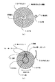
図1(a)は、第1実施形態の時計用ぜんまい装置1を説明するために模式的に示す平面図である。
ひげぜんまい2には、他の部材と嵌合するための接続部が2つある例を示している。この接続部には貫通孔8を有していて、この貫通孔8に嵌合する固定部材により、フレームやテンプ受などの図示しない部材に固定される。なお、この図には、図面を見やすくするために固定部材は省略している。
[Description of First Embodiment: FIGS. 1 and 2]
FIG. 1A is a plan view schematically showing the timepiece mainspring device 1 of the first embodiment.
The hairspring 2 shows an example in which there are two connection portions for fitting with other members. The connecting portion has a through hole 8 and is fixed to a member (not shown) such as a frame or a balance holder by a fixing member fitted into the through hole 8. In this figure, the fixing member is omitted for easy viewing of the drawing.
2つの接続部は、ぜんまいの板状部分の巻き始めとなる内周固定部と巻き終わりとなる終端固定部との2箇所に一体的に設けている。それぞれが、ひげ玉3とひげ持5の部分に相当する。そして固定部材は、これらひげ玉3とひげ持5とを固定するテン真4とひげ持ピン6(図2を参照)にそれぞれ相当する。以後の説明では、そのように呼称する。 The two connecting portions are integrally provided at two locations, that is, an inner periphery fixing portion that is the winding start of the mainspring plate-shaped portion and a terminal fixing portion that is the winding end. Each corresponds to a portion of the beard ball 3 and the whiskers 5. The fixing member corresponds to the tenth truer 4 and the beard pin 6 (see FIG. 2) for fixing the beard ball 3 and the beard 5 respectively. In the following description, it will be called as such.
図1(b)は、その接続部の水平断面を示す拡大断面図である。
この図の接続部はひげ玉3を例にしている。したがって、この図においての固定部材はテン真4となる。このテン真4とひげ玉3との間は、圧入しやすいように所定のクリアランスを設けているが、図面上そのクリアランスは実際のものとは異なるので注意されたい。
FIG.1 (b) is an expanded sectional view which shows the horizontal cross section of the connection part.
The connecting portion in this figure is an example of a whistle ball 3. Therefore, the fixing member in this figure is the tenth true 4. A predetermined clearance is provided between the tenth truth 4 and the whistle ball 3 so as to facilitate press-fitting, but it should be noted that the clearance is different from the actual one in the drawing.
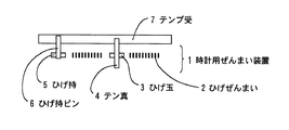
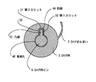
図2は、時計用ぜんまい装置1の側断面を模式的に示す図である。
ひげ玉3はテン真4に嵌合しており、テン真4はテンプ受7に軸支されている。ひげ持
5はひげ持ピン6に嵌合しており、ひげ持ピン6はテンプ受7に固定されている軸体である。
FIG. 2 is a diagram schematically showing a side cross section of the timepiece mainspring device 1.
The whisker ball 3 is fitted to the tenth stem 4, and the tenth stem 4 is pivotally supported by the balance holder 7. The beard 5 is fitted to the beard pin 6, and the beard pin 6 is a shaft body fixed to the balance 7.
ひげぜんまい2は、シリコンを主成分とする材料から成り、特に限定しないが、例えば、厚さ20〜50μm、幅100〜200μmの薄板状の渦巻き形状をしている。
ひげぜんまい2は、例えば、シリコン基板の表面に所定の部材のマスクを形成し、ディープRIEなどの公知のドライエッチング技術を用いて形成する。形成工程そのものは公知技術であるので、その説明は省略する。
The hairspring 2 is made of a material mainly composed of silicon, and is not particularly limited. For example, the hairspring 2 has a thin spiral shape with a thickness of 20 to 50 μm and a width of 100 to 200 μm.
The hairspring 2 is formed, for example, by forming a mask of a predetermined member on the surface of the silicon substrate and using a known dry etching technique such as deep RIE. Since the formation process itself is a known technique, its description is omitted.
ここでひげぜんまい2の接続部の詳細について、主に図1(b)を用いて説明する。
図1(b)に示すように、固定部材であるテン真4には、凸部12が設けてある。凸部12はひげ玉3が回転運動したときにずれないように設けるものであり、ひげぜんまい2の回転に対する抵抗体となっている。
Here, the detail of the connection part of the hairspring 2 will be described mainly with reference to FIG.
As shown in FIG. 1B, the tenth 4 which is a fixing member is provided with a convex portion 12. The convex portion 12 is provided so as not to be displaced when the whistle ball 3 is rotated, and serves as a resistance against rotation of the hairspring 2.
ひげ玉3には貫通孔8が形成されている。貫通孔8はテン真4と嵌合するためのものである。貫通孔8の大きさなど、その形状はテン真4が所定のクリアランスを有して嵌合できるような大きさとなっている。貫通孔8の内周面には、凸部12と対応する位置に凹部9が形成されている。 A through hole 8 is formed in the whistle ball 3. The through hole 8 is for fitting with the tenth true 4. The shape, such as the size of the through hole 8, is such that the tenth 4 can be fitted with a predetermined clearance. A concave portion 9 is formed on the inner peripheral surface of the through hole 8 at a position corresponding to the convex portion 12.
ひげ玉3には、凹部9の近傍に第1スリット10a、10bと第2スリット11とが設けてある。
これらスリットは、図1(b)の例では、第1スリットが2箇所、第2スリットが1か所設ける例を示している。これらスリットは、凹部9の凸部12と当接する面に弾性力を付与するために設けている。
The whisker ball 3 is provided with first slits 10 a and 10 b and a second slit 11 in the vicinity of the recess 9.
In the example of FIG. 1B, these slits show an example in which two first slits and one second slit are provided. These slits are provided to apply an elastic force to the surface of the concave portion 9 that contacts the convex portion 12.
第1スリット10a、10bは、凹部9の深さ方向に対して平行して設けている。つまり、図1(b)に示すひげ玉3を円形と見立てると、その法線方向に並行して長く設けている。 The first slits 10 a and 10 b are provided in parallel to the depth direction of the recess 9. That is, when the whisker ball 3 shown in FIG. 1B is considered to be circular, it is provided long in parallel to the normal direction.
ひげぜんまい2の回転方向が図面正面から見て左右方向に往復するようになっているため、凸部12が凹部9と当接する方向も2箇所である。このため、凸部12に対して図面右側に第1スリット10a、同左側に第1スリット10bを配することで、回転方向のどちらにも上述の弾性力を付与できる構成となっている。 Since the rotation direction of the hairspring 2 reciprocates in the left-right direction when viewed from the front of the drawing, there are also two directions in which the convex portion 12 contacts the concave portion 9. For this reason, the first slit 10a on the right side of the drawing and the first slit 10b on the left side of the convex portion 12 are arranged so that the above-described elastic force can be applied in both directions of rotation.
第2スリット11は、ひげ玉3の凹部9の底面近傍に、この底面と平行して設けてある。つまり、図1(b)に示すひげ玉3を円形と見立てると、その接線方向に並行して設けており、第1スリット10a、10bと直交する方向に長く設けている。 The second slit 11 is provided in the vicinity of the bottom surface of the concave portion 9 of the whistle ball 3 in parallel with the bottom surface. That is, when the whisker 3 shown in FIG. 1B is considered to be circular, it is provided in parallel with the tangential direction, and is provided long in the direction orthogonal to the first slits 10a and 10b.
このスリットにより、ひげぜんまい2の接続部であるひげ玉3を、回転軸であるテン真4と組み付けるときに発生するテン真4の長手方向(図面手前から奥の方向)に掛かる力と、ひげぜんまい2が駆動運動によって伸縮及び拡張運動をするときに発生するテン真4の回転方向(図面左右方向)に掛かる力とを緩和することができる。このことにより、ひげぜんまい2の組み付け及び稼働時に伴って発生しがちなひげ玉3の破損を防止することができる。 Due to this slit, the force applied in the longitudinal direction (from the front to the back of the drawing) of the balance stem 4 generated when the whistle ball 3 which is the connecting portion of the hairspring 2 is assembled with the balance stem 4 which is the rotating shaft, It is possible to relieve the force applied in the rotation direction (the left-right direction in the drawing) of the balance stem 4 that is generated when the mainspring 2 expands and contracts by the driving motion. As a result, it is possible to prevent damage to the whistle ball 3 that tends to occur during the assembly and operation of the hairspring 2.
以上の説明では、ひげ玉3に第1スリット10a、10bと第2スリット11とを双方備える構成を説明したが、もちろんこれに限定されない。
例えば、凹部9と凸部12とのクリアランスが一定でなく、第1スリット10b側のみクリアランスが殆どないような場合は、第1スリット10aのみ設けてもよい。
また、例えば、凹部9と凸部12とのクリアランスが一定でなく、第1スリット10a
側のみクリアランスが殆どなく、凹部9の底面方向と凸部12の先端部分とのクリアランスが比較的大きい場合は、第1スリット10aと第2スリット11とを設けてもよい。
In the above description, the configuration in which the whistle ball 3 includes both the first slits 10a and 10b and the second slit 11 has been described, but the present invention is not limited to this.
For example, when the clearance between the concave portion 9 and the convex portion 12 is not constant and there is almost no clearance only on the first slit 10b side, only the first slit 10a may be provided.
Further, for example, the clearance between the concave portion 9 and the convex portion 12 is not constant, and the first slit 10a.
When there is almost no clearance only on the side, and the clearance between the bottom surface direction of the concave portion 9 and the tip portion of the convex portion 12 is relatively large, the first slit 10a and the second slit 11 may be provided.
いずれの場合も、ひげ玉3とテン真4とのクリアランス、ひげ玉3やテン真4の材質などを鑑みて、自由に選択できる。大切なことは、ひげぜんまい2とテン真4とを組み付けるときに係る力とひげぜんまい2が回転運動をしたときに凹部9と凸部12との間に掛かる力を緩和するようにスリットを備えればよいのである。 In either case, it can be freely selected in view of the clearance between the whistle ball 3 and the tenth trueness 4, the material of the beard ball 3 and the tenth trueness 4, and the like. What is important is that a slit is provided to alleviate the force applied when assembling the balance spring 2 and the balance spring 4 and the force applied between the recess 9 and the projection 12 when the balance spring 2 rotates. It only has to be done.
[第2実施形態の説明:図3]
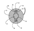
図3は、第2実施形態の時計用ぜんまい装置のぜんまいに有する接続部の水平断面を示す拡大断面図である。
図3に示す第2実施形態の時計用ぜんまい装置が、図1に示す第1実施形態の時計用ぜんまい装置と異なるところは、ひげ玉13の貫通孔18には凹部19並びに第1スリット20及び第2スリット21が、それぞれ180度の対向位置に2カ所に設けられ、テン真14にはひげ玉13の2個の凹部19に対応して2個の凸部22が設けられているところである。
[Description of Second Embodiment: FIG. 3]
FIG. 3 is an enlarged cross-sectional view showing a horizontal cross section of a connection portion included in the mainspring of the timepiece mainspring device of the second embodiment.
The timepiece spring device of the second embodiment shown in FIG. 3 differs from the timepiece spring device of the first embodiment shown in FIG. 1 in that the through
図3に示す構成によれば、ひげ玉13がテン真14から受ける衝撃力を2分の1に分散して緩和することができる。
According to the configuration shown in FIG. 3, the impact force that the
[第3実施形態の説明:図4]
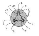
図4は、第3実施形態の時計用ぜんまい装置のぜんまいに有する接続部の水平断面を示す拡大断面図である。
図4に示す第3実施形態の時計用ぜんまい装置が、図1に示す第1実施形態の時計用ぜんまい装置と異なるところは、ひげ玉23の貫通孔28には凹部29並びに第1スリット30及び第2スリット31が、それぞれ120度の対向位置に等間隔に3カ所に設けられ、テン真24にはひげ玉23の3個の凹部29に対応して3個の凸部32が設けられているところである。
[Description of Third Embodiment: FIG. 4]
FIG. 4 is an enlarged cross-sectional view showing a horizontal cross section of a connection portion included in the mainspring of the timepiece mainspring device of the third embodiment.
The timepiece spring device of the third embodiment shown in FIG. 4 is different from the timepiece spring device of the first embodiment shown in FIG. 1 in that the through
図4に示す構成によれば、ひげ玉23がテン真24から受ける衝撃力を3分の1に分散して緩和することができる。
According to the configuration shown in FIG. 4, the impact force that the
[第4実施形態の説明:図5、図4]
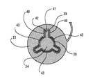
図5は、第4実施形態の時計用ぜんまい装置のぜんまいに有する接続部の水平断面を示す拡大断面図である。
第4実施形態の時計用ぜんまい装置が、すでに説明した3つの実施形態と異なるところは、ひげ玉の貫通孔の湾曲面に並行してスリットを設けている点である。
[Description of Fourth Embodiment: FIGS. 5 and 4]
FIG. 5: is an expanded sectional view which shows the horizontal cross section of the connection part which has in the mainspring of the mainspring for timepieces of 4th Embodiment.
The timepiece mainspring device of the fourth embodiment is different from the already described three embodiments in that a slit is provided in parallel with the curved surface of the through-hole of the whiskers.
図4に示す第3実施形態を元に説明すると、図5に示す第4実施形態の時計用ぜんまい装置は、ひげ玉33の貫通孔38には凹部39並びに第1スリット40及び第2スリット41が、それぞれ120度の対向位置に等間隔に3カ所に設けられ、テン真34にはひげ玉33の3個の凹部39に対応して3個の凸部42が設けられている。
Referring to the third embodiment shown in FIG. 4, in the watch mainspring device of the fourth embodiment shown in FIG. 5, the through
そして、ひげ玉33の貫通孔38の周辺、つまり凹部39同士の間に、貫通孔38に沿って円弧状の第3スリット43が等間隔に3カ所に設けられている。
Then, arc-shaped third slits 43 are provided at three positions at equal intervals along the through
図5に示す構成によれば、ひげ玉33のテン真34と対向する部分はさらにスリットにより柔軟な構造となり、テン真34から受ける衝撃力を更に緩和することができる。
According to the configuration shown in FIG. 5, the portion of the
[第5実施形態の説明:図6、図1、図2]
図6は、第5実施形態の時計用ぜんまい装置のぜんまいに有する接続部の水平断面を示す拡大断面図であって、ぜんまい装置の終端固定部の接続部であるひげ持5の水平断面を示す図である。ぜんまいの接続部をひげ玉3とした第1の実施形態の変形例であって、接続部をひげ持5とした例である。
[Explanation of Fifth Embodiment: FIGS. 6, 1 and 2]
FIG. 6 is an enlarged cross-sectional view showing a horizontal cross section of a connection portion of the mainspring of the timepiece mainspring according to the fifth embodiment, and shows a horizontal cross section of the whistle 5 which is a connection portion of a terminal fixing portion of the mainspring device. FIG. This is a modification of the first embodiment in which the mainspring connection portion is a whistle ball 3, and the connection portion is a whisker 5.
図6に示すように、その構成は図1(b)に示すひげ玉3と同一の形状を有し、図2に示すように、ひげ持5にはテンプ受7に固定されたひげ持ピン6が固定部材として係合されている。図6において、ひげ持5には貫通孔48が形成されており、貫通孔48には、固定部材としてのひげ持ピン6が一定のクリアランスを有して嵌合している。ひげ持ピン6には貫通孔48と嵌合する部分に凸部52を有し、貫通孔48の内周面には凸部52と対応するように凹部49が形成されている。 As shown in FIG. 6, the configuration has the same shape as the whisker ball 3 shown in FIG. 1 (b). As shown in FIG. 6 is engaged as a fixing member. In FIG. 6, a through hole 48 is formed in the whisker 5, and a whisker pin 6 as a fixing member is fitted in the through hole 48 with a certain clearance. The whisker pin 6 has a convex portion 52 at a portion that fits into the through hole 48, and a concave portion 49 is formed on the inner peripheral surface of the through hole 48 so as to correspond to the convex portion 52.
ひげ持5には凹部49の近傍に凹部49の深さ方向に対して平行な第1スリット50が形成されている。また、ひげ持5の凹部49の底面近傍には凹部49の底面に平行な第2スリット51が形成されている。
A
このスリットにより、ひげぜんまい2の接続部であるひげ持5を、固定部材であるひげ持ピン6と組み付けるときに発生する割れがなくなる。 This slit eliminates cracks that occur when the whisker 5 that is the connecting portion of the hairspring 2 is assembled with the whisker pin 6 that is a fixing member.
図6に示す第5実施形態の説明は、すでに説明した実施形態と同様に変形が可能である。例えば、ひげ持ピン6に設ける凸部の52の数や、それに対応するひげ持5に設ける凹部49の数などである。もちろん、第4実施形態のように、ひげ玉の貫通孔の湾曲面に並行してスリットを設けてもよいことは無論である。 The description of the fifth embodiment shown in FIG. 6 can be modified in the same manner as the already described embodiment. For example, the number of convex portions 52 provided on the beard pin 6 and the number of concave portions 49 provided on the beard 5 corresponding thereto. Of course, as in the fourth embodiment, it goes without saying that a slit may be provided in parallel with the curved surface of the through-hole of the whisker ball.
この発明によれば、脆性材料のぜんまいをじん性材料や延性材料で形成する固定部材に圧入できる。それぞれが小さい部品サイズであっても製造工程を増やすことなくぜんまい装置を構成できるため、小型の腕時計用として好適である。 According to the present invention, the mainspring of the brittle material can be press-fitted into the fixing member formed of the tough material or the ductile material. Even if each of them has a small component size, the mainspring device can be configured without increasing the number of manufacturing steps, which is suitable for a small wristwatch.
1 時計用ぜんまい装置
2 ひげぜんまい
3、13、23、33 ひげ玉
4、14、24、34 テン真
5 ひげ持
6 ひげ持ピン
7 テンプ受
8、18、18、38、48 貫通孔
9、19、29、39、49 凹部
10a、10b、20、30、40、50 第1スリット
11、21、31、41,51 第2スリット
12、22、32、42、52 凸部
43 第3スリット、
DESCRIPTION OF SYMBOLS 1 Clock spring apparatus 2
Claims (5)
前記固定部材と前記ぜんまいとの一方は、前記貫通孔と嵌合する部分に凸部を有し、
前記固定部材と前記ぜんまいとの他方は、前記接続部に有する前記貫通孔の内周面に、前記凸部と対応するように凹部を有し、
前記接続部は、前記凹部の前記凸部と当接する面に弾性力を付与するスリットを有することを特徴とする時計用ぜんまい装置。 In the mainspring of the timepiece constituted by a mainspring having silicon as a main component and having a through hole in a connecting portion for fitting with another member, and a fixing member fitted into the through hole,
One of the fixing member and the mainspring has a convex portion in a portion fitted with the through hole,
The other of the fixing member and the mainspring has a concave portion on the inner peripheral surface of the through hole in the connection portion so as to correspond to the convex portion,
The timepiece mainspring device according to claim 1, wherein the connection portion includes a slit that applies an elastic force to a surface of the concave portion that contacts the convex portion.
Priority Applications (1)
| Application Number | Priority Date | Filing Date | Title |
|---|---|---|---|
| JP2013066192A JP2014190816A (en) | 2013-03-27 | 2013-03-27 | Spring device for timepiece |
Applications Claiming Priority (1)
| Application Number | Priority Date | Filing Date | Title |
|---|---|---|---|
| JP2013066192A JP2014190816A (en) | 2013-03-27 | 2013-03-27 | Spring device for timepiece |
Publications (1)
| Publication Number | Publication Date |
|---|---|
| JP2014190816A true JP2014190816A (en) | 2014-10-06 |
Family
ID=51837207
Family Applications (1)
| Application Number | Title | Priority Date | Filing Date |
|---|---|---|---|
| JP2013066192A Pending JP2014190816A (en) | 2013-03-27 | 2013-03-27 | Spring device for timepiece |
Country Status (1)
| Country | Link |
|---|---|
| JP (1) | JP2014190816A (en) |
Cited By (5)
| Publication number | Priority date | Publication date | Assignee | Title |
|---|---|---|---|---|
| EP3432080A1 (en) * | 2017-07-18 | 2019-01-23 | Richemont International S.A. | Clockwork component |
| EP3432082A1 (en) * | 2017-07-18 | 2019-01-23 | Richemont International S.A. | Regulating mechanism |
| EP3432081A1 (en) * | 2017-07-18 | 2019-01-23 | Richemont International S.A. | Timepiece assembly |
| KR20190072465A (en) * | 2017-12-15 | 2019-06-25 | 니바록스-파 에스.에이. | Mainspring for a movement of a timepiece and method for manufacturing the same |
| JP2020008572A (en) * | 2018-07-10 | 2020-01-16 | ブランパン・エス アー | Timer component with non-magnetic shaft-shaped part made from ceramic |
-
2013
- 2013-03-27 JP JP2013066192A patent/JP2014190816A/en active Pending
Cited By (11)
| Publication number | Priority date | Publication date | Assignee | Title |
|---|---|---|---|---|
| EP3432080A1 (en) * | 2017-07-18 | 2019-01-23 | Richemont International S.A. | Clockwork component |
| EP3432082A1 (en) * | 2017-07-18 | 2019-01-23 | Richemont International S.A. | Regulating mechanism |
| EP3432081A1 (en) * | 2017-07-18 | 2019-01-23 | Richemont International S.A. | Timepiece assembly |
| CH714000A1 (en) * | 2017-07-18 | 2019-01-31 | Richemont Int Sa | Watchmaking assembly comprising a watch component fixed on an axis. |
| CH714001A1 (en) * | 2017-07-18 | 2019-01-31 | Richemont Int Sa | Regulating organ for watch movement. |
| CH713999A1 (en) * | 2017-07-18 | 2019-01-31 | Richemont Int Sa | Watch component intended to be fixed on an axis. |
| KR20190072465A (en) * | 2017-12-15 | 2019-06-25 | 니바록스-파 에스.에이. | Mainspring for a movement of a timepiece and method for manufacturing the same |
| JP2019109231A (en) * | 2017-12-15 | 2019-07-04 | ニヴァロックス−ファー ソシエテ アノニム | Mainspring of watch movement and method of manufacturing the same |
| KR102412691B1 (en) * | 2017-12-15 | 2022-06-23 | 니바록스-파 에스.에이. | Mainspring for a movement of a timepiece and method for manufacturing the same |
| US11392090B2 (en) | 2017-12-15 | 2022-07-19 | Nivarox-Far S.A. | Mainspring for a movement of a timepiece and method for manufacturing the same |
| JP2020008572A (en) * | 2018-07-10 | 2020-01-16 | ブランパン・エス アー | Timer component with non-magnetic shaft-shaped part made from ceramic |
Similar Documents
| Publication | Publication Date | Title |
|---|---|---|
| JP2014190816A (en) | Spring device for timepiece | |
| CN101390022B (en) | Micromechanical parts with formed holes for assembly on shafts | |
| JP5823180B2 (en) | Method for manufacturing watch balance spring / spring assembly with micro-machinable material or silicon | |
| JP6276864B2 (en) | Watch wheel set | |
| JP2012078358A (en) | Spiral-spring and balance-wheel regulating member | |
| JP6209181B2 (en) | Ankle for escapement mechanism of watch movement | |
| JP2014215297A (en) | Timepiece component for accommodating integration member | |
| JP6025201B2 (en) | Rotating part, movement, watch, and rotating part manufacturing method | |
| JP2014115293A (en) | Assembling device utilizing deformation of elastic arm | |
| JP2015143673A (en) | Balance with hairspring, movement, and timepiece | |
| JP5627611B2 (en) | Nail fixing assembly system | |
| JP6133767B2 (en) | Hairspring and method for manufacturing the same | |
| CN105425570A (en) | Mechanical component, mechanical component manufacturing method, movement, and timepiece | |
| JP2023532440A (en) | clock oscillator with flexible pivot | |
| JP2017102108A (en) | Protection of micromachined material watch parts | |
| JP2016173356A (en) | Manufacturing method of silicon machine component | |
| JP6537177B2 (en) | Watch gears, ankles, balances, watch movements, and mechanical watches | |
| JP7407287B2 (en) | Clock display mechanism | |
| KR101971377B1 (en) | Watch hand | |
| JP2010190888A (en) | Machine component, timepiece, and manufacturing method of the machine component | |
| JP6199114B2 (en) | Clock spring device | |
| JP6853077B2 (en) | Watch parts, movements and watches | |
| JP2012215183A (en) | Mechanical part assembly, method of manufacturing the same, and timepiece | |
| JP2010243429A (en) | clock | |
| JP2015179071A (en) | Manufacturing method of balance spring, and balance spring |