JP2014190833A - Icp analysis apparatus - Google Patents
Icp analysis apparatus Download PDFInfo
- Publication number
- JP2014190833A JP2014190833A JP2013066578A JP2013066578A JP2014190833A JP 2014190833 A JP2014190833 A JP 2014190833A JP 2013066578 A JP2013066578 A JP 2013066578A JP 2013066578 A JP2013066578 A JP 2013066578A JP 2014190833 A JP2014190833 A JP 2014190833A
- Authority
- JP
- Japan
- Prior art keywords
- waste liquid
- spray chamber
- icp analyzer
- wall surface
- discharge port
- Prior art date
- Legal status (The legal status is an assumption and is not a legal conclusion. Google has not performed a legal analysis and makes no representation as to the accuracy of the status listed.)
- Pending
Links
Images

Landscapes
- Investigating, Analyzing Materials By Fluorescence Or Luminescence (AREA)
Abstract
【課題】廃液の流れの変動を抑制し、比較的安価なICP分析装置を提供する。
【解決手段】ICP分析装置1は、スプレーチャンバ10と、ネブライザ20と、プラズマトーチ30と、試料容器40と、ドレイン管50と、から概略構成されている。スプレーチャンバ10の排出口15の内壁面10a、排出管16の内壁面16a及びドレイン管50の内壁面50aには、毛管作用を備えた廃液捕捉部60が設けられている。即ち、廃液捕捉部60は、スプレーチャンバ10の排出口15の近傍に設けられている。廃液捕捉部60は、スプレーチャンバ10内で生じた廃液41dが排出口15流れてきた時、毛細管現象によって廃液41dを捕えることができる。
【選択図】図1
To provide a relatively inexpensive ICP analyzer that suppresses fluctuations in the flow of waste liquid.
An ICP analyzer 1 is generally composed of a spray chamber 10, a nebulizer 20, a plasma torch 30, a sample container 40, and a drain tube 50. On the inner wall surface 10a of the discharge port 15 of the spray chamber 10, the inner wall surface 16a of the discharge tube 16, and the inner wall surface 50a of the drain tube 50, a waste liquid capturing unit 60 having a capillary action is provided. That is, the waste liquid capturing unit 60 is provided in the vicinity of the discharge port 15 of the spray chamber 10. The waste liquid capture unit 60 can capture the waste liquid 41d by capillary action when the waste liquid 41d generated in the spray chamber 10 flows into the discharge port 15.
[Selection] Figure 1
Description
本発明は、ICP(高周波誘導結合プラズマ)発光分光分析装置およびICP−質量分析装置(MS)として使用されるICP分析装置に関する。 The present invention relates to an ICP (high frequency inductively coupled plasma) emission spectroscopic analyzer and an ICP analyzer used as an ICP-mass spectrometer (MS).
ICP分析装置において、ICP分析を精度良く行うにはプラズマの安定が必要であり、そのためにはスプレーチェンバ内の圧力を一定に保つことが重要である。スプレーチェンバ内の圧力を変動させる要因の一つに廃液の処理の問題がある。この廃液の処理方法を改善した提案がなされている(特許文献1参照)。図3に示される特許文献1には、スプレーチェンバ101とこのスプレーチェンバ101に貯溜する液面の高さを一定に保つために設けられたU字管102との間に上部が密閉された廃液溜となるバッフア容器103を設置し、スプレーチェンバ101の液面の上下変動が抑えられ、圧力変動が低減されたICP分析装置100が開示されている。
In an ICP analyzer, it is necessary to stabilize the plasma in order to perform ICP analysis with high accuracy. To this end, it is important to keep the pressure in the spray chamber constant. One of the factors that cause the pressure in the spray chamber to fluctuate is the problem of waste liquid treatment. The proposal which improved the processing method of this waste liquid is made | formed (refer patent document 1). In
しかしながら、特許文献1では、スプレーチェンバ101に貯溜する液面の高さを一定に保つためにバッファ容器103が必要であり、バッファ容器103を設置するための空間を設けなければならずICP分析装置100全体が大型化してしまい、また、部材を多く使用することによりコストアップになるという問題を生じていた。
However, in
本発明は、上記事由に鑑みてなされたものであり、その目的は、廃液の流れの変動を抑制し、比較的安価なICP分析装置を提供することにある。 The present invention has been made in view of the above reasons, and an object thereof is to provide a relatively inexpensive ICP analyzer that suppresses fluctuations in the flow of waste liquid.
本発明のICP分析装置は、ネブライザで溶液試料をスプレーチャンバを経てプラズマトーチに導入し、前記溶液試料の成分を分析するICP分析装置であって、スプレーチャンバから廃液を排出する排出口に接続された管の内壁面に、毛細管現象によって廃液を捕える廃液捕捉部が設けられている。 The ICP analyzer of the present invention is an ICP analyzer that analyzes a component of a solution sample by introducing a solution sample into a plasma torch through a spray chamber with a nebulizer, and is connected to a discharge port for discharging waste liquid from the spray chamber. A waste liquid trapping part that captures the waste liquid by capillary action is provided on the inner wall surface of the pipe.
前記ICP分析装置は、前記管は略S字型に湾曲されたドレイントラップ部を含み、前記廃液捕捉部が前記排出口と前記ドレイントラップ部との間に設けられていることが好ましい。 In the ICP analyzer, it is preferable that the tube includes a drain trap part curved in a substantially S shape, and the waste liquid capturing part is provided between the discharge port and the drain trap part.
前記ICP分析装置は、前記廃液捕捉部が前記内壁面に貼付された繊維シートにより構成されていることが好ましい。 It is preferable that the ICP analyzer is constituted by a fiber sheet in which the waste liquid capturing unit is attached to the inner wall surface.
前記ICP分析装置は、前記廃液捕捉部が前記内壁面に形成された溝により構成されることが好ましい。 In the ICP analyzer, it is preferable that the waste liquid capturing unit is constituted by a groove formed in the inner wall surface.
本発明によれば、毛管作用を備える廃液捕捉部をスプレーチャンバの排出口に接続された管の内壁面に設けることにより、毛細管現象によって廃液の液滴が緩やかに廃液捕捉部伝わって、ドレイントラップに落ちていくため、廃液の急激な変動が抑えられ、スプレーチャンバやプラズマトーチ内の体積変動が極めて少なく、ICP分析装置による分析に影響を与えることがない。また、廃液捕捉部を管の内壁面に設けるだけで良く、ICP分析装置全体の形状や大きさを変える必要がなく、簡単な繊維シートの貼付や溝の加工等で済み、比較的安価で分析精度の向上したICP分析装置を提供できる。 According to the present invention, by providing the waste liquid capturing part having a capillary action on the inner wall surface of the tube connected to the discharge port of the spray chamber, the liquid droplets of the waste liquid are gently transferred to the waste liquid capturing part by the capillary phenomenon, and the drain trap. Therefore, the rapid fluctuation of the waste liquid is suppressed, the volume fluctuation in the spray chamber and the plasma torch is extremely small, and the analysis by the ICP analyzer is not affected. In addition, it is only necessary to provide a waste liquid capture part on the inner wall surface of the tube, and there is no need to change the shape and size of the entire ICP analyzer. An ICP analyzer with improved accuracy can be provided.
以下、本発明に係るICP分析装置の好適な実施形態を、図1〜図2に基づいて詳述する。 Hereinafter, a preferred embodiment of the ICP analyzer according to the present invention will be described in detail with reference to FIGS.
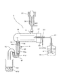
図1は、本発明に係るICP分析装置の一例を示す概念図である。 FIG. 1 is a conceptual diagram showing an example of an ICP analyzer according to the present invention.
ICP分析装置1は、ICP(高周波誘導結合プラズマ)発光分光分析装置およびICP−質量分析装置(MS)等であり、スプレーチャンバ10と、ネブライザ20と、プラズマトーチ30と、試料容器40と、ドレイン管50と、から概略構成されている。
The
スプレーチャンバ10は有底円筒形状を成し、スプレーチャンバ10の開放端には、ネブライザ20を保持したネブライザアダプタ21が密着し、スプレーチャンバ10内の気密性が確保されている。また、スプレーチャンバ10の上部には試料導入出口11が設けられ、高周波コイル31を備えるプラズマトーチ30と気密的に接続されている。ネブライザ20の他端部は、スプレーチャンバ10内にキャリアガス(アルゴンガス等)を導入する導入管22が接続され、更に、試料容器40の溶液試料41内にその先端が浸漬するように配置され試料容器40内の溶液試料41をスプレーチャンバ10内に導入する試料導入管42が接続されている。
The
そして、スプレーチャンバ10の他端(開放端と反対側)の下部には、溶液試料41の廃液41dが排出される排出口15を備える排出管16が設けられ、排出管16はS字状のドレイン管50と気密的に接続されている。ドレイン管50は、廃液41dを一時的に溜めるドレイントラップ部51を備え、ドレイン管50の先端はドレインタンク52に連結されている。また、スプレーチャンバ10の排出口15の内壁面10a、排出管16の内壁面16a及びドレイン管50の内壁面50aには、毛管作用を備えた廃液捕捉部60が設けられている。即ち、図1において廃液捕捉部60の上端位置は、スプレーチャンバ10の排出口15の近傍になる。また、廃液41dがドレイン管50内に導入された際、廃液捕捉部60の少なくとも一部がドレイン管50によってトラップされた廃液41dの内部に浸るように、廃液捕捉部60の形成位置、特に図1での下端位置が規定される。廃液捕捉部60は、スプレーチャンバ10内で生じた廃液41dが排出口15から流れてきた時、毛細管現象によって廃液41dを捕えることができる。
A
キャリアガス(アルゴンガス)が導入管22から供給され、スプレーチャンバ10内にキャリアガスがネブライザ20の先端から噴出され、負圧吸引によって試料容器40の溶液試料41が吸い上げられ、試料導入管42を通ってネブライザ20の先端から試料が噴射される。噴射した試料は、スプレーチャンバ10で粒子の均一化と気流の安定化が図られ、プラズマトーチ30に導かれる。そして、プラズマトーチ30の先端部において高周波コイル31に高周波電流を流し、キャリアガスが電離されてプラズマを発生させ、溶液試料41の試料分子(又は原子)は加熱・励起されて発光する。この発光光を取り出して、スペクトル線の波長から資料に含まれる元素の定性分析とスペクトル線の強度から元素の定量分析を行う。
Carrier gas (argon gas) is supplied from the
噴出した溶液試料41のうち所定の粒径以上の溶液試料41の大部分は、廃液41dとなって排出口15から排出し、排出管16及びドレイン管50を通ってドレイントラップ部51に一時的に溜まり、所定の量以上になるとドレインタンク52に排出される。
Most of the solution sample 41 having a predetermined particle diameter or more out of the ejected solution sample 41 becomes
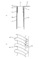
図2は、本発明に係る廃液捕捉部の一例で、(a)は第1の実施例を示す図1のA部拡大図、(b)は第2の実施例を示す部分拡大斜視図である。 FIG. 2 is an example of a waste liquid capturing unit according to the present invention, in which (a) is an enlarged view of part A of FIG. 1 showing the first embodiment, and (b) is a partially enlarged perspective view showing the second embodiment. is there.
廃液捕捉部60の第1の実施例は、毛管作用のある繊維シート61である。繊維シート61としては、例えば無機質繊維を主体とする毛管保水性の不織布よりなる補水材(セラミックペーパー等)であり、例えば、厚さ1mm、かさ密度0.25g/cm3の材質が選択可能である。繊維シート61は、スプレーチャンバ10の排出口15の内壁面10a、排出管16の内壁面16a及びドレイン管50の内壁面50aに、接着材等で貼付されている。
The first embodiment of the waste
廃液捕捉部60の第2の実施例は、毛管作用のある凹凸形状の溝62である。溝62は、スプレーチャンバ10の排出口15の内壁面10a、排出管16の内壁面16a及びドレイン管50の内壁面50aを加工して螺旋状に形成される。また、溝62の大きさは、毛管作用の効率を良好とするために、例えば、深さD1が0.2mm、山幅D2と谷幅D3が0.1mmであることが好ましい。
The second embodiment of the waste
ドレイン管50のS字形状(サイホン構造)によりスプレーチャンバ10内の圧力が一定に保たれてはいるが、廃液41dが所定以上の大きさとなってドレイントラップ部51に落ちるとスプレーチャンバ10の体積変動が大きくなり、ひいては試料導入出口11等を介して繋がっているプラズマトーチ30にも体積変動が伝わり、分析に影響を与えることになる。本発明では、毛細管現象によって廃液41dの液滴が緩やかに伝わる廃液捕捉部60が設けられており、廃液41dの急激な変動が抑えられ、体積変動が極めて少なく、分析に影響を与えることがないICP分析装置を提供できる。
Although the pressure in the
廃液捕捉部60は、スプレーチャンバ10の排出口15の近傍に設けられていることを上述した。この近傍とは、スプレーチャンバ10の排出口15に至る部分から排出口15の先端及び排出口15と接続するドレイン管50を含む領域である。また、廃液捕捉部60は排出口15からドレイントラップ部51間のどの部分に設けられていても良く、また、全体、部分的、所定の幅毎、等、自由に設けることが可能である。
As described above, the waste
尚、本発明は、上述した実施形態に限定されるものではなく、適宜、変形、改良、等が可能である。その他、上述した実施形態における各構成要素の材質、形状、寸法、数値、形態、数、配置箇所、等は本発明を達成できるものであれば任意であり、限定されない。例えば、図1に示した廃液捕捉部60は、ドレイン管50の内壁面50a全体に設けられてもよい。
In addition, this invention is not limited to embodiment mentioned above, A deformation | transformation, improvement, etc. are possible suitably. In addition, the material, shape, dimension, numerical value, form, number, arrangement location, and the like of each component in the above-described embodiment are arbitrary and are not limited as long as the present invention can be achieved. For example, the waste
本発明に係るICP分析装置は、例えば、廃液をスプレーチャンバからドレイントラップ部に毛細管現象を利用して緩やかに滴下できる用途に適用可能である。 The ICP analyzer according to the present invention can be applied, for example, to an application in which waste liquid can be gently dripped from a spray chamber to a drain trap part using a capillary phenomenon.
1:ICP分析装置
10:スプレーチャンバ
10a:内壁面
15:排出口
16:排出管
16a:内壁面
20:ネブライザ
30:プラズマトーチ
40:試料容器
41:溶液試料
41d:廃液
50:ドレイン管
50a:内壁面
51:ドレイントラップ部
60:廃液捕捉部
61:繊維シート
62:溝
1: ICP analyzer 10:
Claims (4)
スプレーチャンバから廃液を排出する排出口に接続された管の内壁面に、毛細管現象によって廃液を捕える廃液捕捉部が設けられた、ICP分析装置。 An ICP analyzer that introduces a solution sample with a nebulizer through a spray chamber into a plasma torch and analyzes the components of the solution sample,
An ICP analyzer in which a waste liquid capturing unit that captures waste liquid by capillarity is provided on the inner wall surface of a pipe connected to a discharge port for discharging the waste liquid from the spray chamber.
前記管は略S字型に湾曲されたドレイントラップ部を含み、前記廃液捕捉部が前記排出口と前記ドレイントラップ部との間に設けられた、ICP分析装置。 The ICP analyzer according to claim 1,
The ICP analyzer, wherein the tube includes a drain trap part curved in a substantially S shape, and the waste liquid capturing part is provided between the discharge port and the drain trap part.
前記廃液捕捉部が前記内壁面に貼付された繊維シートにより構成される、ICP分析装置。 The ICP analyzer according to claim 1 or 2,
An ICP analyzer in which the waste liquid capturing unit is constituted by a fiber sheet affixed to the inner wall surface.
前記廃液捕捉部が前記内壁面に形成された溝により構成される、ICP分析装置。 The ICP analyzer according to claim 1 or 2,
An ICP analyzer in which the waste liquid capturing part is constituted by a groove formed in the inner wall surface.
Priority Applications (1)
| Application Number | Priority Date | Filing Date | Title |
|---|---|---|---|
| JP2013066578A JP2014190833A (en) | 2013-03-27 | 2013-03-27 | Icp analysis apparatus |
Applications Claiming Priority (1)
| Application Number | Priority Date | Filing Date | Title |
|---|---|---|---|
| JP2013066578A JP2014190833A (en) | 2013-03-27 | 2013-03-27 | Icp analysis apparatus |
Publications (1)
| Publication Number | Publication Date |
|---|---|
| JP2014190833A true JP2014190833A (en) | 2014-10-06 |
Family
ID=51837222
Family Applications (1)
| Application Number | Title | Priority Date | Filing Date |
|---|---|---|---|
| JP2013066578A Pending JP2014190833A (en) | 2013-03-27 | 2013-03-27 | Icp analysis apparatus |
Country Status (1)
| Country | Link |
|---|---|
| JP (1) | JP2014190833A (en) |
Cited By (1)
| Publication number | Priority date | Publication date | Assignee | Title |
|---|---|---|---|---|
| US9754773B1 (en) | 2016-05-12 | 2017-09-05 | Thermo Finnigan Llc | Internal solvent trap with drain |
-
2013
- 2013-03-27 JP JP2013066578A patent/JP2014190833A/en active Pending
Cited By (1)
| Publication number | Priority date | Publication date | Assignee | Title |
|---|---|---|---|---|
| US9754773B1 (en) | 2016-05-12 | 2017-09-05 | Thermo Finnigan Llc | Internal solvent trap with drain |
Similar Documents
| Publication | Publication Date | Title |
|---|---|---|
| CN106898536B (en) | Liquid sample introduction system and method for analytical plasma spectrometer | |
| CN105188937B (en) | The apparatus and method introduced for fluid sample | |
| CN105190282B (en) | Device and method for the fluid sample for being mixed with analytical equipment to be introduced | |
| US5454274A (en) | Sequential combination low temperature condenser and enclosed filter solvent removal system, and method of use | |
| JP5459867B2 (en) | Analysis method and analysis system | |
| RU2015142075A (en) | CELLER FOR LASER ABLATION | |
| AU2012355318B2 (en) | Nebulizer and analysis equipment | |
| CN104661758B (en) | Apparatus and method for improving the treating capacity in spectrometry | |
| JP5740525B2 (en) | Ionization method, ionization apparatus, and mass spectrometry system. | |
| US11232939B2 (en) | Methods and systems for feedback control of direct sampling interfaces for mass spectrometric analysis | |
| JP2014190833A (en) | Icp analysis apparatus | |
| US20170154762A1 (en) | Trap replacement mechanism and microparticle composition analyzing apparatus | |
| JP2004125404A (en) | Sample heating device | |
| JP6795095B2 (en) | Plasma generator, luminescence analyzer and mass spectrometer equipped with this, and device state determination method | |
| JP2009121846A (en) | Sample liquid delivery pump and ICP emission spectrometer using the liquid delivery pump | |
| US20170069476A1 (en) | Microparticle composition analyzing apparatus | |
| JPH11142336A (en) | ICP analyzer | |
| US12546636B2 (en) | Acoustic control and characterization of sampling interface | |
| JPH1144644A (en) | ICP analyzer | |
| JP2014211377A (en) | Particle analyzer | |
| JPH0244201Y2 (en) | ||
| JPWO2023127646A5 (en) | ||
| JPS60209148A (en) | Closed circulation chamber for ICP analysis | |
| JP2005024237A (en) | Gas humidification device | |
| JP2005083818A (en) | Icp analyzer |
Legal Events
| Date | Code | Title | Description |
|---|---|---|---|
| RD02 | Notification of acceptance of power of attorney |
Free format text: JAPANESE INTERMEDIATE CODE: A7422 Effective date: 20150202 |