JP2014190840A - Oil film detector - Google Patents
Oil film detector Download PDFInfo
- Publication number
- JP2014190840A JP2014190840A JP2013066696A JP2013066696A JP2014190840A JP 2014190840 A JP2014190840 A JP 2014190840A JP 2013066696 A JP2013066696 A JP 2013066696A JP 2013066696 A JP2013066696 A JP 2013066696A JP 2014190840 A JP2014190840 A JP 2014190840A
- Authority
- JP
- Japan
- Prior art keywords
- signal
- oil film
- light
- threshold
- output signal
- Prior art date
- Legal status (The legal status is an assumption and is not a legal conclusion. Google has not performed a legal analysis and makes no representation as to the accuracy of the status listed.)
- Pending
Links
Images

Landscapes
- Investigating Or Analysing Materials By Optical Means (AREA)
Abstract
【課題】簡単な構成により誤検知要因光に起因する監視負担を解消するようにした油膜検知装置を提供する。
【解決手段】水面からの反射光の受光信号に基づき、外部への出力信号を生成する出力信号生成部と、生成された出力信号を外部に出力する出力部と、を備えた油膜検知装置において、出力信号生成部は、受光信号を、油膜を検知するための受光信号レベルの下限値である第1の閾値L1、及び誤検知要因光の受光信号レベルの下限値である第2の閾値L2と比較し、受光信号が第1の閾値以上かつ第2の閾値未満の範囲にある場合には、油膜の有無を検知する油膜検知信号を生成し、受光信号が前記第1の閾値未満である場合または前記第2の閾値以上である場合には、前記油膜検知信号を生成しないようにした。これにより、油膜以外の物体からの反射光や外乱光を油膜による反射光として誤検知するのを防止する。
【選択図】図4An oil film detection apparatus is provided that eliminates a monitoring burden caused by erroneous detection factor light with a simple configuration.
An oil film detection apparatus comprising: an output signal generation unit that generates an output signal to the outside based on a light reception signal of reflected light from a water surface; and an output unit that outputs the generated output signal to the outside. The output signal generation unit outputs the received light signal as a first threshold L 1 that is a lower limit value of the received light signal level for detecting the oil film, and a second threshold value that is a lower limit value of the received light signal level of the erroneous detection factor light. compared to L 2, if the received light signal is in the range of less than the first threshold value or more and the second threshold value, it generates an oil film detection signals for detecting the presence or absence of the oil film is less than the light-receiving signal is the first threshold value If the value is equal to or greater than the second threshold value, the oil film detection signal is not generated. This prevents erroneous detection of reflected light or disturbance light from an object other than the oil film as reflected light from the oil film.
[Selection] Figure 4
Description
本発明は、水面からの反射光を受光してその受光信号を処理することにより油膜を検出する油膜検知装置に関するものである。 The present invention relates to an oil film detection device that detects an oil film by receiving reflected light from a water surface and processing the received light signal.
水と油との反射率の違いを利用し、浄水場や河川、湖沼等の水面に光を照射してその反射光の強度を測定することにより、水面における油膜の有無を検知するという油膜検知方法を用いた油膜検知装置が、例えば特許文献1,特許文献2により知られている。
このうち、特許文献1に記載された油膜検知器は、光源から照射した光が水面で反射した反射光を受光してその受光信号のピーク値をホールドし、そのピークホールド値を変換した電流信号が、水と検知対象油の反射光受光レベルの中間値に設定された設定値を超えた場合には、油膜警報接点信号を出力するようになっている。また、アルミ箔などの反射し易い浮遊物が滞留している場合は、電流信号と異常の継続時間とを判定し、エラー警報接点信号を出力するようになっている。
Oil film detection that detects the presence or absence of an oil film on the water surface by irradiating the water surface of water purification plants, rivers, lakes, etc. with light and measuring the intensity of the reflected light using the difference in reflectance between water and oil An oil film detection device using the method is known from
Among these, the oil film detector described in
また、特許文献2には、水面を検出するセンサ部の出力信号を第1,第2の閾値とそれぞれ比較してこれらの閾値を超えた合計時間の比率を求めることにより、水面の波立ちや、ビニール片等の反射物が存在する場合の誤検出を防止し、また、第1,第2の閾値を超えた合計時間をそれぞれ座標軸とする二次元領域を複数の警報ランクに割り当てることで、各閾値を超える信号強度の頻度を反映させた多様な警報を出力させる油検知装置の警報判定方法が開示されている。
In addition,
特許文献1に記載された従来技術では、受光信号のピークホールド値が所定の閾値を超えた場合には、油膜検知信号(油膜警報接点信号)が出力される。このため、アルミ箔やビニール片等の浮遊物からの反射光やカメラのフラッシュ等の外乱光(以下、これらを誤検知要因光という)によるピーク値を検知した際に、遠隔の監視装置には、油膜検知信号が入力され、モニターへの表示や音声等によるアラームを発生させてしまう。すなわち、別途エラー警報接点信号が出力されるとしても、油膜検知信号が出力されることに変わりはなく、誤検知要因光に起因する監視負担が解消されないという問題があった。
In the prior art described in
これに対し、特許文献2によれば、誤検知要因光による油膜検知信号の出力を防止することが一応可能である。しかしながら、この特許文献2では、油膜の有無を判定するためのロジックが複雑であり、油膜検知信号の出力が所望のタイミングで適切に行われない(誤検知を防止できない、あるいは、必要な油膜検知信号が発報されない)場合に、どのように設定を修正すればよいのか分かりにくいという問題があった。
On the other hand, according to
また、従来の油膜検知装置は、受光信号に対応した測定値信号(電流信号等)を出力するが、誤検知要因光を受光した場合には、この測定値信号も受光信号に連動して大きく変化する。出力された測定値信号は、遠隔の監視装置等に入力され、これを監視員が随時確認したり、油膜監視記録として保管したりしているが、この測定値信号からだけでは、測定値信号の変化が誤検知要因光によるものなのか、油膜によるものなのかが判別できず、誤検知要因光に起因する監視負担が解消されないという問題があった。 In addition, the conventional oil film detection device outputs a measurement value signal (current signal, etc.) corresponding to the light reception signal. However, when a false detection factor light is received, the measurement value signal is also increased in conjunction with the light reception signal. Change. The output measurement value signal is input to a remote monitoring device, etc., which is monitored by a monitoring person at any time or stored as an oil film monitoring record. It is impossible to determine whether the change is due to erroneous detection factor light or due to an oil film, and there is a problem that the monitoring burden due to the erroneous detection factor light cannot be resolved.
そこで、本発明の解決課題は、簡単な構成により誤検知要因光に起因する監視負担を解消するようにした油膜検知装置を提供することにある。 SUMMARY OF THE INVENTION An object of the present invention is to provide an oil film detection device that eliminates the monitoring burden caused by erroneous detection factor light with a simple configuration.
上記課題を解決するため、請求項1に係る発明は、水面に向けて光を照射する発光部と、前記水面からの反射光を受光し、該受光量に応じた受光信号を出力する受光部と、前記受光信号が入力され、該受光信号に基づき外部への出力信号を生成する出力信号生成部と、前記出力信号生成部が生成した出力信号を外部に出力する出力部と、を備えた油膜検知装置において、
前記出力信号生成部は、前記受光信号を、油膜の有無の判定に用いる第1の閾値、及び誤検知の判定に用いる前記第1の閾値より高レベルの第2の閾値と比較し、
前記受光信号が第1の閾値以上かつ第2の閾値未満の範囲にある場合には、油膜の有無を報知する油膜検知信号を生成し、前記受光信号が前記第1の閾値未満である場合または前記第2の閾値以上である場合には、前記油膜検知信号を生成しないことを特徴とする。
In order to solve the above-mentioned problem, the invention according to
The output signal generation unit compares the light reception signal with a first threshold used for determination of the presence or absence of an oil film and a second threshold higher than the first threshold used for determination of false detection;
When the light reception signal is in a range greater than or equal to the first threshold and less than the second threshold, an oil film detection signal for informing the presence or absence of an oil film is generated, and the light reception signal is less than the first threshold or When it is equal to or greater than the second threshold, the oil film detection signal is not generated.
請求項2に係る発明は、請求項1に記載した油膜検知装置において、前記出力信号生成部は、所定期間以上連続して、前記受光信号が第1の閾値以上かつ第2の閾値未満の範囲にある場合にのみ、前記油膜検知信号を生成することを特徴とする。 According to a second aspect of the present invention, in the oil film detection device according to the first aspect, the output signal generation unit is continuously within a predetermined period or longer, and the received light signal is in a range that is greater than or equal to the first threshold and less than the second threshold. The oil film detection signal is generated only in the case of
請求項3に係る発明は、請求項1または2に記載した油膜検知装置において、前記出力信号生成部は、前記受光信号が前記第2の閾値未満である場合には、前記受光信号に対応した測定値信号を生成し、前記受光信号が前記第2の閾値以上である場合には、前記測定値信号に代えて、直前の測定値信号を保持したホールド信号を生成することを特徴とする。 According to a third aspect of the present invention, in the oil film detection apparatus according to the first or second aspect, the output signal generation unit corresponds to the light reception signal when the light reception signal is less than the second threshold value. A measurement value signal is generated, and when the received light signal is greater than or equal to the second threshold value, a hold signal holding the previous measurement value signal is generated instead of the measurement value signal.
請求項4に係る発明は、請求項1〜3のいずれか1項に記載した油膜検知装置において、前記出力信号生成部は、前記受光信号が前記第2の閾値以上である場合には、異常な受光信号を検出したことを報知する異常信号を生成することを特徴とする。 According to a fourth aspect of the present invention, in the oil film detection device according to any one of the first to third aspects, the output signal generation unit is abnormal when the light reception signal is equal to or greater than the second threshold value. An abnormal signal for notifying that a detected light reception signal has been detected is generated.
請求項5に係る発明は、請求項1〜4のいずれか1項に記載した油膜検知装置において、一定周期で出力されるタイミング信号に基づいて前記受光信号のピーク値をホールドする動作を行うピークホールド手段を備え、前記出力信号生成部は、前記受光信号に代えて、前記ピークホールド手段から出力されるピークホールド値を第1の閾値及び第2の閾値と比較し、該比較の結果に応じた出力信号を生成することを特徴とする。 According to a fifth aspect of the present invention, in the oil film detection device according to any one of the first to fourth aspects, a peak for performing an operation of holding a peak value of the received light signal based on a timing signal output at a constant period. The output signal generation unit includes a hold unit, and compares the peak hold value output from the peak hold unit with the first threshold value and the second threshold value instead of the received light signal, and according to the comparison result. Generating an output signal.
請求項6に係る発明は、請求項5に記載した油膜検知装置において、前記出力信号生成部は、前記タイミング信号をカウントし、前記比較の結果が所定カウント値以上連続して同一であるときに、該比較の結果に応じた出力信号を生成することを特徴とする。 The invention according to claim 6 is the oil film detection device according to claim 5, wherein the output signal generation unit counts the timing signal, and the comparison result is the same continuously for a predetermined count value or more. An output signal corresponding to the result of the comparison is generated.
本発明によれば、出力信号生成部が、受光信号を、油膜の有無の判定に用いる第1の閾値、及び誤検知の判定に用いる前記第1の閾値より高レベルの第2の閾値と比較して、その結果に応じて各種出力信号を生成するため、油膜以外の物体からの反射光や外乱光に起因する油膜検知信号を誤って出力することがない。従って、誤検知要因光に起因する監視負担を解消することができ、また、油膜検知信号の出力が所望のタイミングで適切に行われない場合には、第1の閾値、第2の閾値、カウント値等の設定を変更するだけでよいため、分かりやすく、監視負担を軽減させることができる。
また、必要に応じて、誤検知要因光の受光時には直前の測定値信号を保持したホールド信号を生成することで、誤検知要因光によるノイズが出力信号に含まれるのを防止すると共に、異常信号を出力させて監視等に役立てることもできる。
According to the present invention, the output signal generation unit compares the received light signal with the first threshold value used for determining the presence or absence of the oil film and the second threshold value higher than the first threshold value used for determining the erroneous detection. Since various output signals are generated according to the result, an oil film detection signal caused by reflected light or disturbance light from an object other than the oil film is not erroneously output. Therefore, the monitoring burden caused by the erroneous detection factor light can be eliminated, and if the oil film detection signal is not properly output at a desired timing, the first threshold value, the second threshold value, the count Since it is only necessary to change settings such as values, it is easy to understand and the monitoring burden can be reduced.
In addition, if necessary, when a false detection factor light is received, a hold signal holding the previous measurement value signal is generated to prevent noise due to the false detection factor light from being included in the output signal, and an abnormal signal Can be used for monitoring and the like.
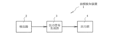
以下、図に沿って本発明の実施形態を説明する。図1は、この実施形態に係る油膜検知装置全体の概略ブロック図である。
図1において、1は油膜検知装置であり、検出器2と、出力信号生成部3を含む図示しない演算制御部と、出力部4とを備えている。
Hereinafter, embodiments of the present invention will be described with reference to the drawings. FIG. 1 is a schematic block diagram of the entire oil film detection apparatus according to this embodiment.
In FIG. 1,
検出器2は、水面に向けて光を照射するLEDやレーザ等により構成される発光部と、水面からの反射光を受光し、その受光量に応じた受光信号を出力する受光部とを備えている。
受光信号は増幅器やA/D変換器等を介して出力信号生成部3に入力される。この出力信号生成部3は、後述するようにピークホールド手段を備えており、一定周期で出力されるタイミング信号に基づいて受光信号をサンプリングしてピーク値をホールドする。そして、このピークホールド値を、油膜の有無の判定に用いる第1の閾値、及び誤検知の判定に用いる前記第1の閾値より高レベルの第2の閾値と比較して、その結果に応じて各種出力信号を生成するようになっている。すなわち、出力信号を生成する条件を満たしたときに、必要な信号を生成するようになっている。
なお、検出器2がピークホールド手段を備え、出力信号生成部3は、入力されたピークホールド値を閾値と比較し、各種出力信号を生成するようになっていてもよい。
The
The received light signal is input to the output
Note that the
出力部4は、油膜検知信号としての警報接点信号と、測定値信号として、受光信号のピークホールド値を例えば4〜20[mA]の直流電流のレベルによって外部に伝える伝送出力信号と、誤検知要因光に起因する異常な受光信号を検出した場合の異常信号とが出力されるようになっており、これらの各信号は、ケーブルを介して遠隔の監視装置等の外部の受信計(図示せず)に送られている。 The output unit 4 includes an alarm contact signal as an oil film detection signal, a transmission output signal that conveys the peak hold value of the received light signal to the outside as a measurement value signal, for example, by a DC current level of 4 to 20 [mA], and a false detection. An abnormal signal when an abnormal received light signal caused by the factor light is detected is output, and each of these signals is received via an external receiver such as a remote monitoring device (not shown). Z)).
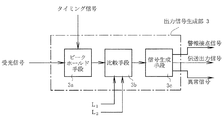
次に、出力信号生成部3の構成及び作用について、図2を参照しつつ説明する。
図2は、出力信号生成部3の機能ブロック図である。図2において、増幅器やA/D変換器等を経た受光信号はピークホールド手段3aに入力され、前記タイミング信号によりサンプリングされてホールドされたピーク値(ピークホールド値)を出力する。なお、受光信号はピークホールド手段を経た後にディジタル信号に変換されるようにしてもよい。
Next, the configuration and operation of the output
FIG. 2 is a functional block diagram of the output
ピークホールド値は、第1の閾値L1及び第2の閾値L2が与えられた比較手段3bに入力されており、この比較手段3bの比較結果により信号生成手段3cは、前述した警報接点信号、伝送出力信号、異常信号を生成する。なお、出力信号生成部3は、CPU等の演算処理装置及びプログラムによって構成されている。
ここで、第1の閾値L1は、水面に存在する油膜による反射光の受光信号レベルの下限値に相当する値である。また、第2の閾値L2は、油膜による反射光の受光信号レベルよりも大きい値であって、前述した誤検知要因光の受光信号レベルの下限値に相当する値である。
Peak hold value is inputted to the comparison means 3b in which the first threshold value L 1 and the second threshold value L 2 is given, the signal generating means 3c the comparison result of the comparison means. 3b, alarm contact signal described above Generate a transmission output signal and an abnormal signal. The output
Here, the first threshold value L 1 is a value corresponding to the lower limit value of the light reception signal level of the reflected light by the oil film present on the surface of the water. The second threshold value L 2 is a value greater than the received light signal level of the reflected light due to the oil film is a value corresponding to the lower limit value of the received light signal level benign triggers light described above.
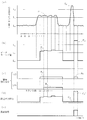
次に、図3は、本実施形態の全体的な動作を示すタイミングチャートであり、図4は出力信号生成部3の動作を示すフローチャートである。
以下、これらの図を参照しつつ本実施形態の動作を説明する。
Next, FIG. 3 is a timing chart showing the overall operation of the present embodiment, and FIG. 4 is a flowchart showing the operation of the output
Hereinafter, the operation of the present embodiment will be described with reference to these drawings.
まず、図3(a)は、図2の出力信号生成部3に入力される受光信号であり、時間軸上の「△」はピークホールド手段3aに入力されるタイミング信号のタイミングを示している。図3(a)における縦軸上のL0は、油膜が存在しない水面からの反射光による受光信号レベルであり、定常時であっても水面の波立ちなどにより振動している。また、第1の閾値L1は、前述したように水面の油膜を検知するための受光信号レベルの下限値であり、第2の閾値L2は誤検知要因光による受光信号レベルの下限値である。
First, FIG. 3A is a light reception signal input to the output
本実施形態では、油膜による光の反射率が水面による反射率よりも高いことに着目し、水面に光を照射してその反射光の強度を測定することにより反射率を求め、これによって水面における油膜の有無を検知するという油膜検知方法を採用している。油の種類によっても異なるが、油膜の反射率は、水面による反射率の約1.5倍から約2倍であるから、閾値L1は、水面による反射率よりも高い値であって、測定対象とする油の種類の油膜の反射率よりも低い値の範囲内で任意に設定される。
また、閾値L2は、水面による反射率の約2倍よりも大きい値に設定されている。
In this embodiment, paying attention to the fact that the reflectance of light by the oil film is higher than the reflectance by the water surface, the reflectance is obtained by irradiating the water surface with light and measuring the intensity of the reflected light. An oil film detection method of detecting the presence or absence of an oil film is adopted. Although the reflectivity of the oil film is approximately 1.5 to approximately 2 times the reflectivity due to the water surface, the threshold L 1 is a value higher than the reflectivity due to the water surface, although it varies depending on the type of oil. It is arbitrarily set within a range of values lower than the reflectance of the oil film of the target oil type.
The threshold L 2 is set to a value greater than about 2 times the reflectance due to the water surface.
図3(b)は、図3(a)の受光信号のピークホールド値を概念的に示した図である。図2のピークホールド手段3aでは、前回〜今回のタイミング信号の間の入力信号レベルのピーク値を今回〜次回のタイミング信号の期間、保持するものとする。 FIG. 3B is a diagram conceptually showing the peak hold value of the received light signal in FIG. The peak hold means 3a in FIG. 2 holds the peak value of the input signal level between the previous and current timing signals during the current and next timing signals.
図3(c)は、警報接点信号を示している。
ここで、(c1)のモードは、図3(b)のピークホールド値が第1の閾値L1と第2の閾値L2との間にある期間、警報接点信号がアクティブになるようにした例である。また、(c2)のモードは、ノイズ等によってピークホールド値が瞬間的に第1の閾値L1を超えるような場合を除外して油膜検知精度を高めるため、例えば図2におけるタイミング信号のカウント値「2」に相当する期間以上にわたってピークホールド値がL1とL2との間にある場合に、警報接点信号がアクティブになるようにした例である。これらのモード(c1),(c2)については、いずれを用いても良い。
図3(d)は伝送出力信号、図3(e)は、誤検知要因光を受光した場合の異常信号であり、信号生成手段3cが図3(c)の警報接点信号、図3(d)の伝送出力信号、図3(e)の異常信号を出力する動作については、図4に示す比較手段3b及び信号生成手段3cの動作と共に以下に説明する。なお、図4において、「S」は閾値と比較する前述のピークホールド値を示すものである。
FIG. 3C shows an alarm contact signal.
Here, mode of (c1), and to a certain period between the threshold L 2 peak hold value is a first threshold value L 1 and the second FIG. 3 (b), the alarm contact signal becomes active It is an example. The mode of (c2), in order to increase the excluded oil film detection accuracy when the peak hold value that exceeds the first threshold value L 1 momentarily due to noise or the like, for example, the count value of the timing signal in FIG. 2 If there between the peak hold value over a period corresponding to "2" is between L 1 and L 2, alarm contact signal is an example of such active. Any of these modes (c1) and (c2) may be used.
3 (d) is a transmission output signal, FIG. 3 (e) is an abnormal signal when receiving a false detection factor light, and the signal generating means 3c is an alarm contact signal of FIG. 3 (c), FIG. 3 (d). ) And the operation for outputting the abnormal signal in FIG. 3E will be described below together with the operations of the comparison means 3b and the signal generation means 3c shown in FIG. In FIG. 4, “S” indicates the above-described peak hold value to be compared with the threshold value.
いま、水面に油膜が存在し、その時の受光信号が図3(a)の信号S1であったとすると、図3(b)に示すように、ピークホールド値P1は油膜検知用の第1の閾値L1と誤検知要因光のための第2の閾値L2との間にある(図4のステップ1 YES,ステップ2 YES)。
そして、比較手段3bが例えばモード(c2)により判定動作を行う場合、タイミング信号のカウント値が「2」以上であることを判定してその結果を信号生成手段3cに出力する(図4のステップ3 YES)。この場合、信号生成手段3cは警報接点信号(油膜検知信号)を生成する条件を満たしたものと判断し、警報接点信号を生成する(オン)。また、信号生成手段3cは、伝送出力信号としてピークホールド値に応じた信号(測定値信号)を生成するが、異常信号を生成する条件は満たしていないものと判断し、異常信号は生成しない(オフ)(図4のステップ4)。
一方、カウント値が「2」未満である場合には、信号生成手段3cは警報接点信号及び異常信号を生成せず(オフ)、伝送出力信号として前述の測定値信号を生成する(図4のステップ5)。
Now, there is an oil film on the water surface, when the light reception signal at that time was signals S 1 in FIG. 3 (a), as shown in FIG. 3 (b), the peak hold value P 1 is the first for oil film detection It is between the second and the threshold value L 2 for the threshold L 1 and benign triggers light (
When the
On the other hand, when the count value is less than “2”, the
このように所定期間(所定カウント値)以上連続して、ピークホールド値P1が油膜検知用の第1の閾値L1と誤検知要因光のための第2の閾値L2との間にある場合にのみ、警報接点信号を生成することで、水面の波立ち等による瞬間的な誤検知要因光に起因する誤警報を少なくすることができる。なお、カウント値は所望のタイミングで油膜検知信号の出力が行われるように適宜決定することができる。 Thus continuously over a predetermined period (a predetermined count value), it is between the second threshold value L 2 for detecting factors light peak hold value P 1 is erroneous and the first threshold value L 1 for oil film detection Only in this case, by generating the alarm contact signal, it is possible to reduce false alarms caused by instantaneous false detection factor light due to water surface undulations. The count value can be appropriately determined so that the oil film detection signal is output at a desired timing.
ここで、比較手段3bがモード(c1)により判定動作を行う場合には、図4におけるステップ3を省略すればよい。また、図4のステップ1における判定がNOであった場合には、カウント値が「2」未満である場合と同様に、信号生成手段3cは警報接点信号及び異常信号を生成せず(オフ)、伝送出力信号として前述の測定値信号を生成する(図4のステップ5)。
なお、図3(c)におけるA1,B1は、それぞれモード(c1),(c2)に従った場合の警報接点信号である。
Here, when the
In FIG. 3 (c), A 1 and B 1 are alarm contact signals when the modes (c1) and (c2) are followed, respectively.
次に、図3(a)の信号S2に示すように、油膜以外による誤検知要因光が受光され、信号S2に対応する図3(b)のピークホールド値P2が第2の閾値L2以上である場合(図4のステップ1 YES,ステップ2 NO)、信号生成手段3cは警報接点信号を生成せず(オフ)、伝送出力信号として直前の測定値信号を保持したホールド信号を生成し、異常信号を生成する(オン)(図4のステップ6)。なお、図4のステップ6の実行前にステップ3と同様のステップを実行するようにしてもよい。
ここで、図3(c)のモード(c1)におけるA2は、ピークホールド値P2に対応する警報接点信号を仮想的に示したものであり、本実施形態ではこの警報接点信号を生成しないようにしたため、誤検知要因光に起因する誤警報は出力されない。
Next, as shown in the signal S 2 in FIG. 3 (a), is received is detected factors light erroneous than the oil film, the peak hold value P 2 is a second threshold value in FIG. 3 corresponding to the signal S 2 (b) If L 2 or more (
Here, A 2 in the mode (c 1) of FIG. 3 (c) virtually indicates an alarm contact signal corresponding to the peak hold value P 2 , and this alarm contact signal is not generated in this embodiment. As a result, false alarms due to false detection factor light are not output.
また、この実施形態では、図3(d)の伝送出力信号については、図3(b)のピークホールド値P2に応じた信号である伝送出力信号C2’を生成せずに、直前の(前サンプル周期の)伝送出力信号C2を保持したホールド信号を生成する。これにより、誤検知要因光による測定データがノイズとして伝送出力信号に含まれるのを未然に防止することが可能である。
更に、ピークホールド値P2に対応する警報接点信号を生成しない代わりに、ピークホールド値P2に同期させて図3(e)の異常信号を生成することにより、高レベルの受光信号を発生させるような事象(例えば水面上の金属による反射光や外乱光の入射など)が発生したことを異常として外部に知らせ、監視等に役立てることができる。
Further, in this embodiment, the transmission output signal of FIG. 3D is generated without generating the transmission output signal C 2 ′ that is a signal corresponding to the peak hold value P 2 of FIG. (prior sample period) to generate a hold signal holding the transmission output signal C 2. Thereby, it is possible to prevent the measurement data due to the erroneous detection factor light from being included in the transmission output signal as noise.
Further, instead of having to generate an alarm contact signal corresponding to the peak hold value P 2, by generating an abnormality signal shown in FIG. 3 (e) in synchronization with the peak hold value P 2, to generate a high-level received light signal It is possible to inform the outside that such an event (for example, the incident of reflected light or disturbance light from a metal on the water surface) has occurred and use it for monitoring or the like.
上記のように本実施形態によれば、出力信号生成部3が、受光信号のピークホールド値を、油膜の有無の判定に用いる第1の閾値、及び誤検知の判定に用いる前記第1の閾値より高レベルの第2の閾値と比較して、その結果に応じて各種出力信号を生成するため、油膜以外の金属等による反射光やカメラのフラッシュ等の外乱光に起因する油膜検知信号を誤って出力することがない。従って、誤検知要因光に起因する監視負担を解消することができる。
また、必要に応じて、誤検知要因光の受光時には直前の測定値信号を保持したホールド信号を生成することで、誤検知要因光によるノイズが出力信号に含まれるのを防止すると共に、異常信号を出力させて監視等に役立てることもできる。
更に、油膜検知信号の出力が所望のタイミングで適切に行われない場合には、第1の閾値、第2の閾値、カウント値等の設定を変更するだけでよいため、分かりやすく、監視負担を軽減させることができる。
なお、本発明による油膜検知装置は、上述の実施形態に限られるものではなく、例えば、油膜検知結果等を表示するための表示部や、表示の切り替えや設定の変更を行うための入力部を備えていてもよい。
As described above, according to the present embodiment, the output
In addition, if necessary, when a false detection factor light is received, a hold signal holding the previous measurement value signal is generated to prevent noise due to the false detection factor light from being included in the output signal, and an abnormal signal Can be used for monitoring and the like.
Furthermore, if the oil film detection signal is not properly output at the desired timing, it is only necessary to change the settings of the first threshold value, the second threshold value, the count value, etc. It can be reduced.
The oil film detection device according to the present invention is not limited to the above-described embodiment, and includes, for example, a display unit for displaying an oil film detection result, an input unit for switching display and changing settings. You may have.
本発明は、水質監視装置や水質分析装置における油膜検知に利用することができる。 The present invention can be used for oil film detection in water quality monitoring devices and water quality analysis devices.
1:油膜検知装置
2:検出器
3:出力信号生成部
3a:ピークホールド手段
3b:比較手段
3c:信号生成手段
4:出力部
1: Oil film detection device 2: Detector 3: Output
Claims (6)
前記水面からの反射光を受光し、該受光量に応じた受光信号を出力する受光部と、
前記受光信号が入力され、該受光信号に基づき外部への出力信号を生成する出力信号生成部と、
前記出力信号生成部が生成した出力信号を外部に出力する出力部と、
を備えた油膜検知装置において、
前記出力信号生成部は、前記受光信号を、油膜の有無の判定に用いる第1の閾値、及び誤検知の判定に用いる前記第1の閾値より高レベルの第2の閾値と比較し、
前記受光信号が第1の閾値以上かつ第2の閾値未満の範囲にある場合には、油膜の有無を報知する油膜検知信号を生成し、前記受光信号が前記第1の閾値未満である場合または前記第2の閾値以上である場合には、前記油膜検知信号を生成しないことを特徴とする油膜検知装置。 A light emitting unit that emits light toward the water surface;
A light receiving unit that receives reflected light from the water surface and outputs a light reception signal according to the amount of light received;
An output signal generation unit that receives the light reception signal and generates an output signal to the outside based on the light reception signal;
An output unit for outputting the output signal generated by the output signal generation unit to the outside;
In the oil film detection device comprising
The output signal generation unit compares the light reception signal with a first threshold used for determination of the presence or absence of an oil film and a second threshold higher than the first threshold used for determination of false detection,
When the light reception signal is in a range greater than or equal to the first threshold and less than the second threshold, an oil film detection signal for informing the presence or absence of an oil film is generated, and the light reception signal is less than the first threshold or The oil film detection device does not generate the oil film detection signal when it is equal to or greater than the second threshold value.
前記出力信号生成部は、所定期間以上連続して、前記受光信号が第1の閾値以上かつ第2の閾値未満の範囲にある場合にのみ、前記油膜検知信号を生成することを特徴とする油膜検知装置。 In the oil film detection apparatus according to claim 1,
The output signal generation unit generates the oil film detection signal only when the light reception signal is in a range that is greater than or equal to a first threshold value and less than a second threshold value for a predetermined period or longer. Detection device.
前記出力信号生成部は、前記受光信号が前記第2の閾値未満である場合には、前記受光信号に対応した測定値信号を生成し、前記受光信号が前記第2の閾値以上である場合には、前記測定値信号に代えて、直前の測定値信号を保持したホールド信号を生成することを特徴とする油膜検知装置。 In the oil film detection apparatus according to claim 1 or 2,
The output signal generation unit generates a measurement value signal corresponding to the light reception signal when the light reception signal is less than the second threshold, and when the light reception signal is greater than or equal to the second threshold. Is an oil film detection device that generates a hold signal holding the previous measurement value signal instead of the measurement value signal.
前記出力信号生成部は、前記受光信号が前記第2の閾値以上である場合には、異常な受光信号を検出したことを報知する異常信号を生成することを特徴とする油膜検知装置。 In the oil film detection apparatus according to any one of claims 1 to 3,
The output signal generation unit generates an abnormal signal for notifying that an abnormal received light signal has been detected when the received light signal is equal to or greater than the second threshold value.
一定周期で出力されるタイミング信号に基づいて前記受光信号のピーク値をホールドする動作を行うピークホールド手段を備え、
前記出力信号生成部は、前記受光信号に代えて、前記ピークホールド手段から出力されるピークホールド値を第1の閾値及び第2の閾値と比較し、該比較の結果に応じた出力信号を生成することを特徴とする油膜検知装置。 In the oil film detection apparatus according to any one of claims 1 to 4,
Peak holding means for performing an operation of holding the peak value of the received light signal based on a timing signal output at a constant period;
The output signal generation unit compares the peak hold value output from the peak hold means with the first threshold value and the second threshold value instead of the light reception signal, and generates an output signal according to the comparison result. An oil film detection device characterized by:
前記出力信号生成部は、前記タイミング信号をカウントし、前記比較の結果が所定カウント値以上連続して同一であるときに、該比較の結果に応じた出力信号を生成することを特徴とする油膜検知装置。 In the oil film detection apparatus according to claim 5,
The output signal generation unit counts the timing signal, and generates an output signal according to the comparison result when the comparison result is continuously the same as a predetermined count value or more. Detection device.
Priority Applications (1)
| Application Number | Priority Date | Filing Date | Title |
|---|---|---|---|
| JP2013066696A JP2014190840A (en) | 2013-03-27 | 2013-03-27 | Oil film detector |
Applications Claiming Priority (1)
| Application Number | Priority Date | Filing Date | Title |
|---|---|---|---|
| JP2013066696A JP2014190840A (en) | 2013-03-27 | 2013-03-27 | Oil film detector |
Publications (1)
| Publication Number | Publication Date |
|---|---|
| JP2014190840A true JP2014190840A (en) | 2014-10-06 |
Family
ID=51837227
Family Applications (1)
| Application Number | Title | Priority Date | Filing Date |
|---|---|---|---|
| JP2013066696A Pending JP2014190840A (en) | 2013-03-27 | 2013-03-27 | Oil film detector |
Country Status (1)
| Country | Link |
|---|---|
| JP (1) | JP2014190840A (en) |
Citations (5)
| Publication number | Priority date | Publication date | Assignee | Title |
|---|---|---|---|---|
| US5461236A (en) * | 1992-06-09 | 1995-10-24 | Herbert R. Gram | Oil spill detection system |
| JPH11223630A (en) * | 1998-02-06 | 1999-08-17 | Hoechst Reseach & Technology Kk | Chemical or biological species sensing device with opticl fiber utilized, and remote monitoring system using the same |
| JP2002082054A (en) * | 2000-06-20 | 2002-03-22 | Fuji Electric Co Ltd | Alarm detection method for oil detector |
| JP2003149134A (en) * | 2001-11-09 | 2003-05-21 | San Denshi Kogyo Kk | Oil film detector |
| JP2009534632A (en) * | 2006-04-21 | 2009-09-24 | トマテック | Oil leak detector |
-
2013
- 2013-03-27 JP JP2013066696A patent/JP2014190840A/en active Pending
Patent Citations (5)
| Publication number | Priority date | Publication date | Assignee | Title |
|---|---|---|---|---|
| US5461236A (en) * | 1992-06-09 | 1995-10-24 | Herbert R. Gram | Oil spill detection system |
| JPH11223630A (en) * | 1998-02-06 | 1999-08-17 | Hoechst Reseach & Technology Kk | Chemical or biological species sensing device with opticl fiber utilized, and remote monitoring system using the same |
| JP2002082054A (en) * | 2000-06-20 | 2002-03-22 | Fuji Electric Co Ltd | Alarm detection method for oil detector |
| JP2003149134A (en) * | 2001-11-09 | 2003-05-21 | San Denshi Kogyo Kk | Oil film detector |
| JP2009534632A (en) * | 2006-04-21 | 2009-09-24 | トマテック | Oil leak detector |
Non-Patent Citations (1)
| Title |
|---|
| 奥村剛人: "レーザー走査式油膜検知器「ODL−1600型」", JETI, vol. 57, no. 9, JPN6016029330, 20 August 2009 (2009-08-20), pages 155 - 157, ISSN: 0003370014 * |
Similar Documents
| Publication | Publication Date | Title |
|---|---|---|
| US10366590B2 (en) | Smoke detector for event classification and methods of making and using same | |
| US8510068B2 (en) | Photoelectric smoke sensor | |
| JP2021518551A (en) | Laser pulse edge detection for real-time detection | |
| JP2021518556A (en) | Active signal detection using noise floor adaptive identification | |
| JP2021518549A (en) | Selection of LIDAR pulse detector according to pulse type | |
| JPWO2007004606A1 (en) | Ranging device | |
| TW200802196A (en) | Sound wave type smoke detector | |
| KR101784755B1 (en) | Apparatus for learning painting, method thereof and computer recordable medium storing program to perform the method | |
| JP2017156127A (en) | Fire monitoring system and smoke sensor | |
| JP7402160B2 (en) | Distance measuring device and reliability determination method | |
| JP4199785B2 (en) | Distance measuring system and distance measuring method | |
| WO2021095657A1 (en) | Distance measuring device | |
| JP2015155817A (en) | Detection device, fish finder, and detection method | |
| CN113614566A (en) | Distance measurement method, distance measurement device, and program | |
| JP2017162110A (en) | Flame detector | |
| CN113454486A (en) | Proximity sensing based on rate change detection | |
| JP2005106553A5 (en) | ||
| JP6406076B2 (en) | Object detection device, object detection method, and object detection program | |
| JP2016506518A5 (en) | ||
| JP4771795B2 (en) | Optical distance measuring device | |
| TWI500950B (en) | Optical displacement sensor | |
| JP2012068038A (en) | Optical range finder | |
| JP2014163884A (en) | Distance measurement device | |
| JP5573340B2 (en) | Gas detection device and gas detection method | |
| JP7486843B2 (en) | Apparatus and method for generating test data for testing distance determination in optical time-of-flight measurements - Patents.com |
Legal Events
| Date | Code | Title | Description |
|---|---|---|---|
| A621 | Written request for application examination |
Free format text: JAPANESE INTERMEDIATE CODE: A621 Effective date: 20150930 |
|
| A977 | Report on retrieval |
Free format text: JAPANESE INTERMEDIATE CODE: A971007 Effective date: 20160720 |
|
| A131 | Notification of reasons for refusal |
Free format text: JAPANESE INTERMEDIATE CODE: A131 Effective date: 20160801 |
|
| A02 | Decision of refusal |
Free format text: JAPANESE INTERMEDIATE CODE: A02 Effective date: 20170216 |