JP2014190859A - Sludge shut-off device and sludge shut-off method - Google Patents
Sludge shut-off device and sludge shut-off method Download PDFInfo
- Publication number
- JP2014190859A JP2014190859A JP2013067092A JP2013067092A JP2014190859A JP 2014190859 A JP2014190859 A JP 2014190859A JP 2013067092 A JP2013067092 A JP 2013067092A JP 2013067092 A JP2013067092 A JP 2013067092A JP 2014190859 A JP2014190859 A JP 2014190859A
- Authority
- JP
- Japan
- Prior art keywords
- sludge
- blocking device
- partition
- support member
- container
- Prior art date
- Legal status (The legal status is an assumption and is not a legal conclusion. Google has not performed a legal analysis and makes no representation as to the accuracy of the status listed.)
- Pending
Links
Images



Classifications
-
- Y—GENERAL TAGGING OF NEW TECHNOLOGICAL DEVELOPMENTS; GENERAL TAGGING OF CROSS-SECTIONAL TECHNOLOGIES SPANNING OVER SEVERAL SECTIONS OF THE IPC; TECHNICAL SUBJECTS COVERED BY FORMER USPC CROSS-REFERENCE ART COLLECTIONS [XRACs] AND DIGESTS
- Y02—TECHNOLOGIES OR APPLICATIONS FOR MITIGATION OR ADAPTATION AGAINST CLIMATE CHANGE
- Y02E—REDUCTION OF GREENHOUSE GAS [GHG] EMISSIONS, RELATED TO ENERGY GENERATION, TRANSMISSION OR DISTRIBUTION
- Y02E30/00—Energy generation of nuclear origin
- Y02E30/30—Nuclear fission reactors
Landscapes
- Treatment Of Sludge (AREA)
Abstract
【課題】簡素化された構造で核燃料物質を含むスラッジの臨界および広範囲への散逸を防止するスラッジ遮断装置およびスラッジ遮断方法を提供する。
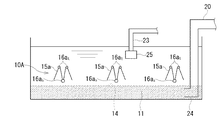
【解決手段】スラッジ遮断装置10Aは、核燃料物質を含むスラッジ11が液体中に沈積している容器12に沈められて容器12の底部に設置される支持部材と、支持部材に支持されるとともに液相と固相の界面14の近傍に配置される仕切手段15aと、界面14を覆うように仕切手段15aを動作させる動作手段16aと、を備える。
【選択図】 図2The present invention provides a sludge blocking device and a sludge blocking method for preventing sludge containing nuclear fuel material from being dissipated to a critical and wide range with a simplified structure.
A sludge blocking device 10A includes a support member that is submerged in a container 12 in which sludge 11 containing nuclear fuel material is deposited in a liquid and is installed at the bottom of the container 12, and is supported by the support member and liquid A partition unit 15a disposed in the vicinity of the interface 14 between the phase and the solid phase; and an operation unit 16a that operates the partition unit 15a so as to cover the interface 14.
[Selection] Figure 2
Description
本発明は、沈積した核燃料物質を含むスラッジを遮断するスラッジ遮断装置およびスラッジ遮断方法に関する。 The present invention relates to a sludge blocking device and a sludge blocking method for blocking sludge containing deposited nuclear fuel material.
原子力発電施設の事故処理をする場合、スラッジとしてタービン建屋の内部などに沈積する核燃料物質を含む物質を外部に排出する場合がある。核燃料物質を含む物質を取り扱う際は、常に、臨界に至る条件を成立させないよう機器設計および取扱いをすることで未臨界を担保する必要がある(例えば、特許文献1または特許文献2)。 When handling accidents at nuclear power generation facilities, there are cases where materials including nuclear fuel materials that deposit in the turbine building as sludge are discharged to the outside. When handling a material containing nuclear fuel material, it is always necessary to ensure subcriticality by designing and handling the equipment so as not to satisfy the critical condition (for example, Patent Document 1 or Patent Document 2).
核燃料物質を含む未臨界の体系がどの程度臨界に近いかを示す指標として、(1)式で表わされる中性子実効増倍率keffが挙げられる。
keff=k∞/(1+M2B2) (1)
ここでk∞は中性子無限増倍率、B2は沈積するスラッジの厚さなどの形状・寸法で決まるバックリング、M2は液体中の核燃料物質の濃度などで決まる中性子移動面積である。
An index indicating how close a subcritical system containing nuclear fuel material is critical is the neutron effective multiplication factor k eff represented by equation (1).
k eff = k ∞ / (1 + M 2 B 2 ) (1)
Here k ∞ neutron infinite multiplication factor, B 2 is buckling determined by the shape and dimensions such as the thickness of the sludge deposit, M 2 is a neutron moving area determined in such a concentration of the nuclear fuel material in a liquid.
(1)式で与えられる中性子実効増倍率keffが臨界の1を十分下回るよう、中性子移動面積M2およびバックリングB2を管理することで臨界管理を行う。(例えば、特許文献1)。
(1)式でkeff<1とし、類似の系に対する推定臨界下限増倍率をkL(<1)として(2)式を得る。
B2>(k∞/kL−1)/M2 (2)
Criticality management is performed by managing the neutron transfer area M 2 and the buckling B 2 so that the effective neutron multiplication factor k eff given by the equation (1) is well below the critical 1. (For example, patent document 1).
In equation (1), k eff <1 and the estimated critical lower limit multiplication factor for a similar system is k L (<1) to obtain equation (2).
B 2 > (k ∞ / k L −1) / M 2 (2)
ある定まった中性子移動面積M2に対しては、(2)式が担保されるようなバックリングB2を与えることで、体系形状による臨界管理を行う。
つまり、核燃料物質を含むスラッジは、一般廃水に沈積する汚泥とは異なり(例えば、特許文献3または特許文献4)、(2)式を満たすよう厳密な臨界管理がされて排出または貯蔵などがされなければならない。
For a certain neutron movement area M 2 , critical control based on the system shape is performed by providing a buckling B 2 that secures the formula (2).
In other words, sludge containing nuclear fuel material differs from sludge deposited in general wastewater (for example, Patent Document 3 or Patent Document 4), and is subjected to strict critical management to satisfy the equation (2) and is discharged or stored. There must be.
上述のように、核燃料物質を含むスラッジは、例えば、排出の際に臨界に達してしまわないよう、その厚さを一定以下に保って排出される必要がある。 As described above, the sludge containing nuclear fuel material needs to be discharged with its thickness kept below a certain level, for example, so as not to reach criticality during discharge.
また、スラッジが臨界に達しなくても、液体を回収する際、スラッジが散逸して液体とともに回収されると、回収した液体についても引き続き臨界管理をする負担が生じる。回収の後の臨界管理の負担を低減するには、回収管に設置されてスラッジを多量に含む液体からスラッジを分離する手段を複数付加しなければならないという課題があった。 Even if the sludge does not reach the criticality, when recovering the liquid, if the sludge is dissipated and recovered together with the liquid, a burden of continuing to manage the criticality of the recovered liquid arises. In order to reduce the burden of criticality management after recovery, there has been a problem that a plurality of means for separating sludge from a liquid containing a large amount of sludge installed in a recovery pipe must be added.
本発明はこのような事情を考慮してなされたもので、簡素化された構造で核燃料物質を含むスラッジの臨界および広範囲への散逸を防止するスラッジ遮断装置およびスラッジ遮断方法を提供することを目的とする。 The present invention has been made in view of such circumstances, and an object of the present invention is to provide a sludge blocking device and a sludge blocking method that prevent the sludge containing nuclear fuel material from critically and widely radiating with a simplified structure. And
本発明にかかるスラッジ遮断装置は、核燃料物質を含むスラッジが液体中に沈積している容器に沈められて前記容器の底部に設置される支持部材と、前記支持部材に支持されるとともに液相と固相の界面の近傍に配置される仕切手段と、前記界面を覆うように前記仕切手段を動作させる動作手段と、を備えるものである。 A sludge blocking device according to the present invention includes a support member that is submerged in a container in which sludge containing nuclear fuel material is deposited in a liquid and is installed at the bottom of the container, and is supported by the support member and has a liquid phase. Partition means disposed in the vicinity of the interface of the solid phase, and operating means for operating the partition means so as to cover the interface.
本発明により、簡素化された構造で核燃料物質を含むスラッジの臨界および広範囲への散逸を防止するスラッジ遮断装置およびスラッジ遮断方法が提供される。 According to the present invention, there is provided a sludge blocking device and a sludge blocking method for preventing sludge containing nuclear fuel material from criticality and wide-area dissipation with a simplified structure.
以下、本発明の実施形態を添付図面に基づいて説明する。
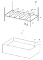
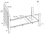
図1は、第1実施形態にかかるスラッジ遮断装置10A(10)を容器12に設置する様子を示す概略図である。
Hereinafter, embodiments of the present invention will be described with reference to the accompanying drawings.
FIG. 1 is a schematic view showing a state in which the
各実施形態にかかるスラッジ遮断装置10Aは、核燃料が破損して液体とともに流動し沈積しうるスラッジ11(図2)となって沈積している原子力発電施設内の各所に適用される。
すなわち、容器12は、例えば、復水器などのタービン建屋の各種設備、原子炉建屋の各種設備または建屋そのものなどであり、その形状は多様である。
The
That is, the
(第1実施形態)
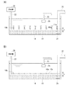
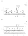
図2は、図2(A)は第1実施形態にかかるスラッジ遮断装置10Aを設置した容器12の断面図であり、図2(B)は図2(A)のスラッジ遮断装置10Aでスラッジ11を遮断した状態を示す図である。
(First embodiment)
2A is a cross-sectional view of the
第1実施形態にかかるスラッジ遮断装置10Aは、図1または図2に示すように、核燃料物質を含むスラッジ11が液体中に容器12に沈められて容器12の底部に設置される支持部材13a(13)と、支持部材13aに支持されるとともに液相と固相の界面14の近傍に配置される仕切手段15a(15)と、界面14を覆うように仕切手段15aを動作させる動作手段16a(16)と、を備える。
As shown in FIG. 1 or FIG. 2, the
さらに、第1実施形態にかかるスラッジ遮断装置10Aは、開口部24からスラッジ11を容器12の外部に排出する排出管20と、スラッジ11を希釈する希釈液または中性子吸収体溶液をスラッジ11に添加する添加管22と、仕切手段15aでスラッジ11を覆った後に仕切手段15aの上部の液体を回収する回収管23と、を備える。
なお、図2(A),(B)において、支持部材13aは省略してある。
Furthermore, the
In FIGS. 2A and 2B, the
支持部材13aは、核燃料物質を含むスラッジ11が液体中に沈積している容器12に沈められ(図1のA方向)、スラッジ11の近傍に設置される。
The
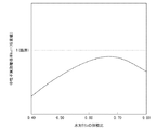
ここで、図3は、水対ウランの体積比に対する中性子実効増倍率keffの変化を示す概略図である。
図3に示されるように、中性子実効増倍率keffは水対ウランの体積比に対して上に凸の相関を持つ。
Here, FIG. 3 is a schematic diagram showing a change in the effective neutron multiplication factor k eff with respect to the volume ratio of water to uranium.
As shown in FIG. 3, the neutron effective multiplication factor k eff has an upwardly convex correlation with the volume ratio of water to uranium.
つまり、スラッジ11の全体量が変化しなくても、スラッジ11の厚さが増加すると臨界に近づくということである。一方、例えば、スラッジ11は、燃料濃縮度が5wt%以下の場合、広範囲に10cm程度以下の厚さで沈積しているときは、沈積する範囲が広範であっても臨界に達しない。すなわち、核燃料物質を含むスラッジ11は、一般廃水に沈積する汚泥とは異なり、臨界に達しないようその厚さが臨界管理される必要がある。
In other words, even if the total amount of the
そこで、支持部材13aは、スラッジ11が沈積する底面からの仕切手段15aの距離を調整する脚部18を備える。そして、界面14から仕切手段15aまでの距離dが、スラッジ11の濃度および厚さに応じて前記(2)式に基づく検討で定まる範囲で調節される。脚部18の長さは自由に決められ、仕切手段15aに界面14が達してもスラッジ11の厚さが十分に臨界を下回るように調整される。
Therefore, the
仕切手段15aは、支持部材13aに支持されるとともに液相と固相の界面14の近傍に配置される。第1実施形態においては、仕切手段15aは、図1および図2(A),(B)に示されるように分割された仕切板である。
The
仕切手段15aは、例えば、ヒンジなどの動作手段16aによって一辺を回転可能に2枚ずつ固定され、他辺をピンチなどの留具19で挟まれて畳まれた状態で設置される。
なお、仕切手段15aまたは支持部材13aの少なくとも一部は、中性子吸収体を含む材質からなると、有効にスラッジ11の臨界を防止できる。
For example, the partitioning means 15a is installed in a state in which two sides are rotatably fixed by an operating means 16a such as a hinge, and the other side is sandwiched and clamped by a
If at least a part of the partitioning means 15a or the
例えば、仕切手段15aを中性子吸収体であるホウ素系の化合物を含むステンレスとする方法や、仕切手段15aの表面にホウ素系の化合物を含む塗料またはシールで被覆する方法がある。なお、中性子吸収体の角材をスラッジ11の近傍に沈設してもよい。
For example, there are a method in which the partitioning means 15a is made of stainless steel containing a boron-based compound that is a neutron absorber, and a method in which the surface of the partitioning means 15a is covered with a paint or seal containing a boron-based compound. Note that a neutron absorber square may be deposited in the vicinity of the
動作手段16aは、例えばヒンジであり、仕切手段15aを支持部材13aに連結し、界面14を覆うように仕切手段15aを動作させる。支持部材13aを設置した後、留具19をはずすと、仕切手段15aの重さで動作手段16aが回転して開き、図2(B)に示されるように界面14を覆う。
The operating means 16a is, for example, a hinge, which connects the partitioning means 15a to the
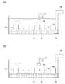
図4(A),(B)はいずれも、第1実施形態のスラッジ遮断装置10Aの変形例を示す図である。なお、図4以降の各図では、添加管22、添加槽26および支持部材13aが適宜省略されている。
4 (A) and 4 (B) are views showing a modification of the
動作手段16aによる仕切手段15aの固定の仕方は、必ずしも2枚を一組とする必要はなく、図4(A)に示すように、幅の広い仕切手段15aを1枚固定することもできる。また、図4(B)に示すように、仕切手段15aの中央を固定してもよい。いずれの場合も、動作手段16aによる回転の後には、仕切手段15aは図2(B)のように界面14を覆う配置となり、スラッジ11の散逸を防止する。
The way of fixing the partitioning means 15a by the operating means 16a does not necessarily need to be a set of two sheets, and one wide partitioning means 15a can be fixed as shown in FIG. Further, as shown in FIG. 4B, the center of the partitioning means 15a may be fixed. In any case, after the rotation by the operating means 16a, the partitioning means 15a is disposed so as to cover the
また、図5も、第1実施形態のスラッジ遮断装置10Aの変形例を示す図である。図5に示されるように、仕切手段15aを支持部材13aに連結する動作手段16as(16a)のほかに、仕切手段15aを他の仕切手段15aに連結する動作手段16at(16a)で仕切手段15aに動作を付与してもよい。
FIG. 5 is also a diagram showing a modification of the
動作手段16atをさらに複数備え、連結される仕切手段15aの数を増加させることもできる。図5においても、設置の後に仕切手段15aを留める留具19(図1)が外され、仕切手段15aの自重により動作手段16aが回転し、仕切手段15aが界面14を覆う。 Further comprising a plurality of operation means 16a t, it is also possible to increase the number of partition means 15a to be connected. Also in FIG. 5, the fastener 19 (FIG. 1) which fastens the partition means 15a after installation is removed, the operating means 16a rotates due to its own weight, and the partition means 15a covers the interface.
排出管20は、開口部24からスラッジ11を容器12の外部に排出する。排出管20は、液体の上部から容器12の底面に向けて沈められてもよいし、スラッジ11付近の容器12の側面に穴をあけて挿入されてもよい。
なお、排出管20をスラッジ遮断装置10Aの一部として予め備えさせると、仕切手段15aおよび排出管20の形状を互いに調整でき、スラッジ11を遮断する効率が上げられる。
The
If the
添加管22は、添加槽26に貯蔵された中性子吸収体溶液またはスラッジ11を希釈する希釈液をスラッジ11に添加する。水などの希釈液および五ホウ酸ナトリウムに代表されるホウ素系やガドリニウム系などの中性子吸収体溶液のいずれも、遮断したスラッジ11の臨界の防止のために添加される。
なお、スラッジ11は必ずしも、容器12の外部に排出される必要はなく、遮断の後に、容器12に貯蔵されたまま臨界管理されてもよい。
The
The
中性子吸収体溶液の添加により(1)式の中性子無限増倍率k∞を小さくできる。また、希釈液を添加することで、液体の外部へ排出した後のスラッジ11の管理が容易となる。ただし、希釈液の添加は実効増倍率keffを増加させることに寄与することもある。よって、スラッジ11の濃度が十分低いことがわかっており、濃度管理もする場合に希釈液が添加できる。
The addition of the neutron absorber solution (1) can be reduced neutron infinite multiplication factor k ∞ of Formula. Moreover, management of the
回収管23は、仕切手段15aでスラッジ11を覆った後に、仕切手段15aの上部の液体を回収する。回収管23の浸水している開口端にはストレーナまたはフィルタなどの除去手段25が装着され、不純物を除去しながら回収する。
The
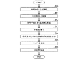
次に第1実施形態にかかるスラッジ遮断装置10Aの動作手順を図13を用いて説明する。図13は各実施形態にかかるスラッジ遮断装置10Aの動作手順を示すフローチャートである。
Next, the operation procedure of the
まず、支持部材13aの脚部18を調節して距離dを変数に含むバックリングB2が(2)式を満たしてスラッジ11が臨界に達しない長さに調節する(ステップS10)。すなわち、脚部18は、仕切手段15aに界面14が達してもスラッジ11の厚さが十分に臨界を下回るように調整される。
First, buckling B 2 including distance d variable by adjusting the
次に、仕切手段15aを畳んだ状態で支持部材13aをスラッジ11の近傍に設置する(ステップS11)。なお、支持部材13aの設置の後に脚部18の長さを調節してもよい。すると、仕切手段15aが界面14の近傍に配置されることになる(ステップS12)。
そして、留具19を外し、仕切手段15aを動作させて界面14を覆う(ステップS13)。
Next, the
And the
次に、添加管22で希釈液または中性子吸収体溶液をスラッジ11に添加する(ステップS14)。そして、スラッジ11を排出管20で容器12の外部に排出する(ステップS15)。また、仕切手段15aの上部に溜まっている液体を回収管23で回収する(ステップS16)。
なお、液体の回収およびスラッジ11の排出は同時であってもどちらかが先であってもよい。また、状況に応じて、スラッジ11は、容器12の外部に排出されずに、容器12に貯蔵されたまま臨界管理されてもよい。
Next, a diluting solution or a neutron absorber solution is added to the
Note that the recovery of the liquid and the discharge of the
以上のように、第1実施形態にかかるスラッジ遮断装置10Aによれば、簡素化された構造で核燃料物質を含むスラッジ11の臨界および広範囲への散逸を防止することができる。さらに、仕切手段15aの上部に貯められた液体へのスラッジ11の混入を低減させることで、回収される液体の核燃料物質の臨界管理が容易になる。
As described above, according to the
(第2実施形態)
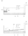
図6(A)は第2実施形態にかかるスラッジ遮断装置10B(10)を設置した容器12の断面図であり、図6(B)は図6(A)のスラッジ遮断装置10Bでスラッジ11を遮断した状態を示す図である。
(Second Embodiment)
FIG. 6A is a cross-sectional view of the
第2実施形態にかかるスラッジ遮断装置10Bは、図6(A),(B)に示されるように、第1実施形態において、重なり合う仕切手段15b(15)どうしがその面上でスライドするものに替わり、動作手段16b(16)はこの仕切手段15bどうしを一定の範囲でスライドさせる機構となる。
As shown in FIGS. 6A and 6B, the
動作手段16bは、例えば、2枚の仕切手段15b(15bs,15bt)の組で、上側の仕切手段15bsと下側の仕切手段15btの板面上に互いに緩やかに噛みあうように設けられた凹凸である。そして接続された駆動部(図示せず)により、仕切手段15bsは仕切手段15btの板面上をスライドして、図6(B)に示すようにスラッジ11を遮断する。
Operation means 16b, for example, two partition means 15b (15b s, 15b t) a set of, as the upper side of the partitioning means 15b s and a lower side of the partition means 15b t plate surface on each other chewing slowly each other It is the unevenness provided. Then the connected drive unit (not shown), the partition means 15b s is slid over the plate surface of the partition means 15b t, blocking the
動作手段16bは、下側の仕切手段15btの板面上に敷かれたレールと上側の仕切手段15bsにつけられてこのレール上を転がるタイヤのようなものであってもよい。
なお、動作手段16bは、上側の仕切手段15bsが下側の仕切手段15btから外れることなく互いの板面を滑らかにスライドできれば、これらの例に限定されない。
Operation means 16b may be one such as tires rolling on the rail attached to the lower side of the partitioning means 15b t partitioning means 15b s rail and upper that is laid on the plate surface of.
The
図7(A)は第2実施形態のスラッジ遮断装置10Bの変形例を示す図であり、図7(B)は図7(A)のスラッジ遮断装置10Bでスラッジ11を遮断した状態を示す図である。動作手段16bは、各仕切手段15bの上下に設けられ、図7(A),(B)に示されるように、1箇所に重ねられた仕切手段15bを界面14の全体に広げて覆うようなものでもよい。
FIG. 7A is a view showing a modification of the
なお、動作手段16bが仕切手段15bどうしをその板面上でスライドさせるものであること以外は、第2実施形態は第1実施形態と同様の構造および動作手順となるので、重複する説明を省略する。図面においても、共通の構成または機能を有する部分は同一符号で示し、重複する説明を省略する。 Since the second embodiment has the same structure and operation procedure as the first embodiment, except that the operating means 16b slides the partitioning means 15b on the plate surface, the redundant description is omitted. To do. Also in the drawings, portions having a common configuration or function are denoted by the same reference numerals, and redundant description is omitted.
このように、第2実施形態にかかるスラッジ遮断装置10Bによれば、簡素化された構造で核燃料物質を含むスラッジ11の臨界および広範囲への散逸を防止することができる。さらに、仕切手段15bの上部に貯められた液体へのスラッジ11の混入を低減させることで、回収される液体の核燃料物質の臨界管理が容易になる。
As described above, according to the
(第3実施形態)
図8(A)は第3実施形態にかかるスラッジ遮断装置10C(10)の斜視図である。第3実施形態にかかるスラッジ遮断装置10Cは、図8(A)に示されるように、仕切手段15c(15)は、可撓性を有するシートであり、動作手段16c(16)は、シートを巻きつけるローラである。
(Third embodiment)
FIG. 8A is a perspective view of a sludge blocking device 10C (10) according to the third embodiment. In the sludge blocking device 10C according to the third embodiment, as shown in FIG. 8A, the partitioning means 15c (15) is a flexible sheet, and the operation means 16c (16) is a sheet. It is a roller to wind.
図中右側の支持部材13bs(13b)は動作手段16cを支持する支持部材13bt(13b)に重ねられて液体中に設置される。設置の後、接続される駆動部(図示せず)により、右側の支持部材13bsは図中のB方向へ引かれる。動作手段16cに巻きつけられた仕切手段15cは、支持部材13bsとともにB方向に引かれてスラッジ11を覆う。
仕切手段15cが可撓性を有するシートであり、支持部材13bsが可動であることにより、スラッジ11または容器12の形状にスラッジ遮断装置10Cを変形できる。
The
A sheet partition means 15c has flexibility, by the supporting
なお、仕切手段15cが可撓性を有するシートであること、動作手段16cがローラであることおよび支持部材13bが可動であること以外は、第3実施形態は第1実施形態と同様の構造および動作手順となるので、重複する説明を省略する。図面においても、共通の構成または機能を有する部分は同一符号で示し、重複する説明を省略する。
The third embodiment has the same structure and structure as the first embodiment except that the partitioning means 15c is a flexible sheet, the operating means 16c is a roller, and the
図8(B)は第3実施形態のスラッジ遮断装置10Cの変形例を示す図である。図8(B)に示すように、支持部材13c(13)の形状は固定され、仕切手段15cに設けられた牽引手段28を引くことで仕切手段15cはB方向にひかれ、スラッジ11の界面14を覆ってもよい。
FIG. 8B is a view showing a modification of the sludge blocking device 10C of the third embodiment. As shown in FIG. 8B, the shape of the
このように、第3実施形態にかかるスラッジ遮断装置10Cによれば、核燃料物質を含むスラッジ11の臨界および広範囲への散逸を防止することができる。さらに、仕切手段15cの上部に貯められた液体へのスラッジ11の混入を低減させることで、回収される液体の核燃料物質の臨界管理が容易になる。
As described above, according to the sludge cutoff device 10C according to the third embodiment, it is possible to prevent the
(第4実施形態)
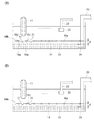
図9(A)は第4実施形態にかかるスラッジ遮断装置10D(10)を設置した容器12の断面図である。第4実施形態にかかるスラッジ遮断装置10Dは、第1実施形態において、仕切手段15d(15)は、沈降してくるスラッジ11を仕切手段15dの底面側に沈積させるとともにその逆流を抑止する逆止手段21を備える。
(Fourth embodiment)
FIG. 9A is a cross-sectional view of the
仕切手段15dの配置の際に未だスラッジ11が沈降してくる場合は、スラッジ11を完全に覆うと、仕切手段15dの上面にスラッジ11が沈積してしまう。すると、スラッジ11を遮断したことにはならず、液体の回収の際などにスラッジ11が散逸し、または臨界を超えてしまう。
If the
そこで、図9(A)に示されるように、仕切手段15dを緩やかに曲げて仕切手段15dどうしを接触させずに重ならせて逆止手段21とし、沈降してくるスラッジ11が仕切手段15dに沈積することを防ぐ。その一方で、仕切手段15dの底面側に沈積したスラッジ11が逆流して散逸することを防ぐ。
Therefore, as shown in FIG. 9 (A), the partitioning means 15d is gently bent so that the partitioning means 15d are overlapped without contacting each other to form a check means 21, and the
図9(B)は第4実施形態のスラッジ遮断装置10Dの変形例を示す図である。図9(B)に示されるように、仕切手段15dの端部に弾力性をもたせて逆止手段21とし、スラッジ11の重さにより端部が撓んでできる隙間からスラッジ11を底面側に沈積させてもよい。
FIG. 9B is a view showing a modification of the
逆止手段21は、その他従来各種のものが知られており、これらのうち任意のものを使用することができる。なお、第1実施形態に限らず、各実施形態において、逆止手段21を備えることができる。また、図9(A),(B)においては、仕切手段15dの一部に逆止手段21を備えた仕切手段15dを記載しているが、仕切手段15の全部を仕切手段15dとしてもよい。 Various other conventional check means 21 are known, and any of these can be used. In addition to the first embodiment, the check means 21 can be provided in each embodiment. 9A and 9B show the partitioning means 15d provided with the check means 21 in a part of the partitioning means 15d, the whole partitioning means 15 may be the partitioning means 15d. .
なお、仕切手段15dが逆止手段21を備えること以外は、第3実施形態は第1実施形態と同様の構造および動作手順となるので、重複する説明を省略する。図面においても、共通の構成または機能を有する部分は同一符号で示し、重複する説明を省略する。 In addition, since 3rd Embodiment becomes a structure and operation | movement procedure similar to 1st Embodiment except that the partition means 15d is provided with the non-return means 21, the overlapping description is abbreviate | omitted. Also in the drawings, portions having a common configuration or function are denoted by the same reference numerals, and redundant description is omitted.
このように、仕切手段15dが逆止手段21を備えることで、スラッジ11が未だ沈降してくる場合でも、仕切手段15dに沈積することを防止するとともに沈積したスラッジ11が散逸すること防止することができる。
Thus, by providing the partitioning means 15d with the check means 21, even when the
このように、第4実施形態にかかるスラッジ遮断装置10Dによれば、簡素化された構造で核燃料物質を含むスラッジ11の臨界および広範囲への散逸を防止することができる。さらに、仕切手段15dの上部に貯められた液体へのスラッジ11の混入を低減させることで、回収される液体の核燃料物質の臨界管理が容易になる。
As described above, according to the
(第5実施形態)
図10は、第5実施形態にかかるスラッジ遮断装置10E(10)の斜視図である。第5実施形態にかかるスラッジ遮断装置10Eは、図10に示されるように、仕切手段15e(15)は、動作手段16d(16)により、第1実施形態の仕切手段15aどうしが幅方向に連結されて一方向にのみに可撓性を有する一方向可撓シートとなる。
(Fifth embodiment)
FIG. 10 is a perspective view of a
仕切手段15eは、支持部材13d(13)の一側面に平行に収納されてスラッジ11の近傍に設置される。設置の後、仕切手段15eが自重により図中のB方向に滑り込むのを防止するストッパ(図示せず)が外され、仕切手段15eは支持部材13dの形状に沿って滑り込む。
なお、仕切手段15eが、支持部材13dの他側面まで滑り込むように脚部18の長さを変え、支持部材13dにスラッジ11の界面14を下回らない程度に傾きを持たせてもよい。
The partition means 15e is housed in parallel with one side surface of the
The length of the
なお、仕切手段15eが一方向可撓シートであること以外は、第5実施形態は第1実施形態と同様の構造および動作手順となるので、重複する説明を省略する。図面においても、共通の構成または機能を有する部分は同一符号で示し、重複する説明を省略する。 Since the fifth embodiment has the same structure and operation procedure as the first embodiment except that the partitioning means 15e is a one-way flexible sheet, a duplicate description is omitted. Also in the drawings, portions having a common configuration or function are denoted by the same reference numerals, and redundant description is omitted.
このように、仕切手段15eが自重でスラッジ11を覆うように配置されることにより、仕切手段15eに動力を付与する駆動部を不要とすることができる。
As described above, the
以上のように、第5実施形態にかかるスラッジ遮断装置10Eによれば、核燃料物質を含むスラッジ11の臨界および広範囲への散逸を防止することができる。さらに、仕切手段15eの上部に貯められた液体へのスラッジ11の混入を低減させることで、回収される液体の核燃料物質の臨界管理が容易になる。
As described above, according to the
(第6実施形態)
図11は、図11(A)は第6実施形態にかかるスラッジ遮断装置10F(10)を設置した容器12の断面図、図11(B)は第6実施形態にかかるスラッジ遮断装置10Fでスラッジ11を遮断した状態を示す図である。
(Sixth embodiment)
11A is a cross-sectional view of the
図11(A)に示されるように、第6実施形態にかかるスラッジ遮断装置10Fは、第1実施形態から第4実施形態で示された仕切手段15(15a〜15e)が、上下方向に複数段配置される。容器12またはスラッジ11の形状に合わせて各段で仕切手段15の種類が選択されて組み合わせられる。1段の仕切手段15でスラッジ11を十分に遮断できない場合でも、仕切手段15が複数段配置されることにより、スラッジ遮断装置10Fの全体で十分な遮断が可能となる。
As shown in FIG. 11A, the
さらに、例えば、遮断性が高い一方で配置の際にスラッジ11を舞い上げてしまう仕切手段15を、先にスラッジ11を舞い上がらせずにある程度遮断する仕切手段15と組み合わせることでそれぞれの仕切手段15の脆弱な部分を強化できる。
Further, for example, the partitioning means 15 that lifts up the
次に、図12は、各実施形態にかかるスラッジ遮断装置10(10A〜10F)を容器12に複数敷き詰めた上面図である。
容器12は、例えば、復水器などのタービン建屋の各種設備、原子炉建屋の各種設備または建屋そのものなどであり、その形状は多様である。そこで、図12に示されるように、スラッジ遮断装置10を複数用いることで容器12の形状または排出管20の配置などに合わせてスラッジ11を不足なく覆う。
Next, FIG. 12 is a top view in which a plurality of sludge blocking devices 10 (10A to 10F) according to each embodiment are spread on the
The
この場合も、第1実施形態から第4実施形態で示されたスラッジ遮断装置10が適宜組み合わせられる。隣り合ったスラッジ遮断装置10どうしを連結させる場合は、必ずしもすべてのスラッジ遮断装置10が脚部18を備える必要はなくなる。
Also in this case, the
なお、仕切手段15またはスラッジ遮断装置10そのものを複数組み合わせること以外は、第6実施形態は各実施形態と同様の構造および動作手順となるので、重複する説明を省略する。図面においても、共通の構成または機能を有する部分は同一符号で示し、重複する説明を省略する。
Except for combining a plurality of partitioning means 15 or
このように、仕切手段15またはスラッジ遮断装置10の全体を複数組み合わせることによって、遮断の脆弱な部分を強化することができる。また、容器12の形状や排出管20の配置などに合わせてスラッジ11を不足なく覆うことができる。
In this way, by combining a plurality of partitioning means 15 or
以上のべた少なくとも一つの実施形態のスラッジ遮断装置10によれば、簡素化された構造で核燃料物質を含むスラッジ11の界面14を覆うことにより、スラッジ11の臨界および広範囲への散逸を防止することが可能となる。さらに、仕切手段15の上部に貯められた液体へのスラッジ11の混入を低減させることで、回収される液体の核燃料物質の臨界管理が容易になる。
According to the
本発明のいくつかの実施形態を説明したが、これらの実施形態は、例として提示したものであり、発明の範囲を限定することは意図していない。これら実施形態は、その他の様々な形態で実施されることが可能であり、発明の要旨を逸脱しない範囲で、種々の省略、置き換え、変更、組み合わせを行うことができる。これら実施形態やその変形は、発明の範囲や要旨に含まれると同様に、特許請求の範囲に記載された発明とその均等の範囲に含まれるものである。 Although several embodiments of the present invention have been described, these embodiments are presented by way of example and are not intended to limit the scope of the invention. These embodiments can be implemented in various other forms, and various omissions, replacements, changes, and combinations can be made without departing from the scope of the invention. These embodiments and their modifications are included in the scope and gist of the invention, and are also included in the invention described in the claims and the equivalents thereof.
10(10A〜10F)…スラッジ遮断装置、11…スラッジ、12…容器、13〔13a,13b(13bs,13bt),13c,13d〕…支持部材、14…界面、15〔15a,15b(15bs,15bt),15c,15d,15e〕…仕切手段、16〔16a(16as,16at),16b,16c,16d〕…動作手段、18…脚部、19…留具、20…排出管、21…逆止手段、22…添加管、23…回収管、24…開口部、25…除去手段、26…添加槽、28…牽引手段、d…距離、B2…バックリング、k∞…中性子無限増倍率、keff…中性子実効増倍率、kL…推定臨界下限増倍率、A,B…方向。 10 (10A to 10F) ... sludge blocking device, 11 ... sludge, 12 ... container, 13 [13a, 13b (13b s , 13b t ), 13c, 13d] ... support member, 14 ... interface, 15 [15a, 15b ( 15 b s , 15 b t ), 15 c, 15 d, 15 e] ... partitioning means, 16 [16 a (16 a s , 16 a t ), 16 b, 16 c, 16 d] ... operating means, 18 ... legs, 19 ... fasteners, 20 ... Discharge pipe, 21 ... check means, 22 ... addition pipe, 23 ... recovery pipe, 24 ... opening, 25 ... removal means, 26 ... addition tank, 28 ... traction means, d ... distance, B 2 ... buckling, k ∞ ... Neutron infinite multiplication factor, k eff ... Neutron effective multiplication factor, k L ... Estimated critical lower limit multiplication factor, A, B ... direction.
Claims (11)
前記支持部材に支持されるとともに液相と固相の界面の近傍に配置される仕切手段と、
前記界面を覆うように前記仕切手段を動作させる動作手段と、を備えることを特徴とするスラッジ遮断装置。 A support member that is submerged in a container in which sludge containing nuclear fuel material is deposited in a liquid and installed at the bottom of the container;
Partition means supported by the support member and disposed in the vicinity of the interface between the liquid phase and the solid phase;
And an operating means for operating the partitioning means so as to cover the interface.
前記動作手段は、前記仕切手段を前記支持部材または他の仕切板に連結することを特徴とする請求項1から請求項6のいずれか1項に記載のスラッジ遮断装置。 The partition means is a divided partition plate,
The sludge blocking device according to any one of claims 1 to 6, wherein the operating unit connects the partition unit to the support member or another partition plate.
前記動作手段は、前記シートを巻きつけるローラであることを特徴とする請求項1から請求項6のいずれか1項に記載のスラッジ遮断装置。 The partition means is a flexible sheet,
The sludge blocking device according to any one of claims 1 to 6, wherein the operating means is a roller for winding the sheet.
前記支持部材に支持される仕切手段を液相と固相の界面の近傍に配置するステップと、
前記界面を覆うように前記仕切手段を動作させるステップと、を含むことを特徴とするスラッジ遮断方法。 Sinking the support member at the bottom of the container in which the sludge containing nuclear fuel material is deposited in the liquid; and
Disposing partition means supported by the support member in the vicinity of the interface between the liquid phase and the solid phase;
Operating the partition means so as to cover the interface.
Priority Applications (1)
| Application Number | Priority Date | Filing Date | Title |
|---|---|---|---|
| JP2013067092A JP2014190859A (en) | 2013-03-27 | 2013-03-27 | Sludge shut-off device and sludge shut-off method |
Applications Claiming Priority (1)
| Application Number | Priority Date | Filing Date | Title |
|---|---|---|---|
| JP2013067092A JP2014190859A (en) | 2013-03-27 | 2013-03-27 | Sludge shut-off device and sludge shut-off method |
Publications (1)
| Publication Number | Publication Date |
|---|---|
| JP2014190859A true JP2014190859A (en) | 2014-10-06 |
Family
ID=51837243
Family Applications (1)
| Application Number | Title | Priority Date | Filing Date |
|---|---|---|---|
| JP2013067092A Pending JP2014190859A (en) | 2013-03-27 | 2013-03-27 | Sludge shut-off device and sludge shut-off method |
Country Status (1)
| Country | Link |
|---|---|
| JP (1) | JP2014190859A (en) |
Citations (3)
| Publication number | Priority date | Publication date | Assignee | Title |
|---|---|---|---|---|
| JPS53126759A (en) * | 1977-04-12 | 1978-11-06 | Takeshi Murakami | Method of drawing sludge |
| JP2002307052A (en) * | 2001-04-11 | 2002-10-22 | Sekisui Chem Co Ltd | Partition structure of storage tank |
| JP2004105859A (en) * | 2002-09-18 | 2004-04-08 | Sekisui Chem Co Ltd | Storage tank and storage tank partition structure |
-
2013
- 2013-03-27 JP JP2013067092A patent/JP2014190859A/en active Pending
Patent Citations (3)
| Publication number | Priority date | Publication date | Assignee | Title |
|---|---|---|---|---|
| JPS53126759A (en) * | 1977-04-12 | 1978-11-06 | Takeshi Murakami | Method of drawing sludge |
| JP2002307052A (en) * | 2001-04-11 | 2002-10-22 | Sekisui Chem Co Ltd | Partition structure of storage tank |
| JP2004105859A (en) * | 2002-09-18 | 2004-04-08 | Sekisui Chem Co Ltd | Storage tank and storage tank partition structure |
Similar Documents
| Publication | Publication Date | Title |
|---|---|---|
| US20150114893A1 (en) | Water pollution trap with replaceable filtration box for top-down cleaning | |
| US7556157B2 (en) | Density current baffle for a clarifier tank | |
| US20160024778A1 (en) | Retrofit catch basin for use in storm water management practice | |
| US10710907B2 (en) | Hydrodynamic separators, assemblies and methods for storm water treatment | |
| US20190264717A1 (en) | Garbage guard apparatus and related methods of installation | |
| US9174148B2 (en) | Launder channel cover with independently openable panel members | |
| Pastore | Reworking the relation between sanitation and the city in Dar es Salaam, Tanzania | |
| Bruneau et al. | Seismic resilience of communities-conceptualization and operationalization | |
| KR20200133656A (en) | Device for excluding early rainwater and filtering rainwater | |
| JP2014190859A (en) | Sludge shut-off device and sludge shut-off method | |
| KR101051452B1 (en) | Eco-Friendly River Garbage Collection Unit | |
| JP6008793B2 (en) | Radioactive substance fragment collection container, collection method, and collection device | |
| US20140110348A1 (en) | Inclined plates for cso | |
| CN113047408B (en) | Rainwater storage tank operation device and method | |
| CN103397681B (en) | A kind of high sediment seawater joint pump house in nuclear power plant method for arranging | |
| JP6524037B2 (en) | Water blocking plate | |
| CN212452527U (en) | Water body overflow emptying power generation device | |
| Pezzaniti et al. | Detention/retention storages for peak flow reduction in urban catchments: effects of spatial deployment of storages | |
| CN206843221U (en) | Multi-stage sewage pretreatment unit | |
| CN215948432U (en) | Stifled device is prevented to municipal administration public works sewer | |
| KR102265834B1 (en) | Odor reduction type septic tank | |
| CN220026342U (en) | Multistage sedimentation tank for building construction site | |
| Othmer, Jr et al. | Performance Evaluation of Structural BMPs: Drain Inlet Inserts (Fossil Filter and Stream Guard) and Oil/Water Separator | |
| Newell et al. | Distribution of Holocene sediment in Chesapeake Bay as interpreted from submarine geomorphology of the submerged landforms, selected core holes, bridge borings and seismic profiles | |
| CN219710232U (en) | Anti-blocking device for water inlet of hydroelectric power generation |
Legal Events
| Date | Code | Title | Description |
|---|---|---|---|
| A621 | Written request for application examination |
Free format text: JAPANESE INTERMEDIATE CODE: A621 Effective date: 20150717 |
|
| A977 | Report on retrieval |
Free format text: JAPANESE INTERMEDIATE CODE: A971007 Effective date: 20160412 |
|
| A131 | Notification of reasons for refusal |
Free format text: JAPANESE INTERMEDIATE CODE: A131 Effective date: 20160419 |
|
| A02 | Decision of refusal |
Free format text: JAPANESE INTERMEDIATE CODE: A02 Effective date: 20161018 |