JP2014190873A - Method for sampling impurity metal and method for analyzing metal component in solution - Google Patents
Method for sampling impurity metal and method for analyzing metal component in solution Download PDFInfo
- Publication number
- JP2014190873A JP2014190873A JP2013067404A JP2013067404A JP2014190873A JP 2014190873 A JP2014190873 A JP 2014190873A JP 2013067404 A JP2013067404 A JP 2013067404A JP 2013067404 A JP2013067404 A JP 2013067404A JP 2014190873 A JP2014190873 A JP 2014190873A
- Authority
- JP
- Japan
- Prior art keywords
- liquid
- collection container
- sample solution
- metal
- gas
- Prior art date
- Legal status (The legal status is an assumption and is not a legal conclusion. Google has not performed a legal analysis and makes no representation as to the accuracy of the status listed.)
- Pending
Links
Images

Landscapes
- Sampling And Sample Adjustment (AREA)
Abstract
【課題】本発明は、サンプリング装置の損傷を抑制した上で、短時間で、かつ精度良く、試料溶液に含まれる不純物金属をサンプリング可能な不純物金属のサンプリング方法を提供することを目的とする。
【解決手段】大気圧下で前記捕集容器13内の試料溶液14を加熱することにより液体14Aを蒸発させ、捕集容器13内の不純物金属14Bを含む残渣を回収する工程を有し、残渣を回収する工程において、捕集容器13内に位置する吹き出し口15Aから試料溶液14の液面14aに向けて清浄なガスを吹き付けるとともに、捕集容器13内に配置された回収口28Aから試料溶液14の蒸気を含むガスを捕集容器13の外に導出する。
【選択図】図1An object of the present invention is to provide an impurity metal sampling method capable of sampling an impurity metal contained in a sample solution in a short time and with high accuracy while suppressing damage to a sampling device.
The method includes a step of evaporating a liquid 14A by heating a sample solution 14 in the collection container 13 under atmospheric pressure and recovering a residue containing an impurity metal 14B in the collection container 13; In the step of collecting the sample solution, a clean gas is blown from the outlet 15A located in the collection container 13 toward the liquid surface 14a of the sample solution 14, and the sample solution is collected from the collection port 28A disposed in the collection container 13. A gas containing 14 vapors is led out of the collection container 13.
[Selection] Figure 1
Description
本発明は、溶液や液体材料ガス等の試料溶液に含まれる被分析対象物のサンプリングに関し、特に、該試料溶液に含まれる不純物金属を捕集する際に使用する不純物金属のサンプリング方法、及び溶液中金属成分の分析方法に関する。 The present invention relates to sampling of an analyte contained in a sample solution such as a solution or a liquid material gas, and in particular, a method for sampling an impurity metal used when collecting an impurity metal contained in the sample solution, and the solution The present invention relates to a method for analyzing medium metal components.
半導体製造工場では近年、製造工程において液体材料、例えばTEOSのような有機液体材料等を用い半導体を製造している。実際の製造にあたっては、液体材料の品質が安定している事を確認するために、当該材料中の被分析成分、例えば、金属不純物を定期的に測定して、その量が要求品質を満足している事を確認する必要がある。 In recent years, semiconductor manufacturing plants manufacture semiconductors using liquid materials, for example, organic liquid materials such as TEOS, in the manufacturing process. In actual production, in order to confirm that the quality of the liquid material is stable, the components to be analyzed, for example, metal impurities in the material are regularly measured, and the amount satisfies the required quality. It is necessary to confirm that.
液体材料中の不純物の定量分析法としては、先ず、防爆構造を施したホットプレートなどを用いて液体試料を蒸発乾固して被分析成分(金属不純物)をサンプリングし、これを溶媒に溶解してICP−MS等で測定する方法が知られている。 As a quantitative analysis method for impurities in a liquid material, first, a liquid sample is evaporated to dryness using a hot plate or the like with an explosion-proof structure, the component to be analyzed (metal impurity) is sampled, and this is dissolved in a solvent. A method of measuring by ICP-MS or the like is known.
しかし、前述の方法では液体試料の蒸発乾固に長時間を要し、その間に外部から環境由来の汚染物質が混入する可能性がある。そのため、金属不純物の正確な定量が困難になることがある。 However, in the above-described method, it takes a long time to evaporate and dry the liquid sample, and there is a possibility that contaminants derived from the environment may be mixed from the outside. Therefore, accurate quantification of metal impurities may be difficult.
そこで、試料溶液周囲を減圧状態にさせることにより溶液の沸点を降下させ、蒸発効率を向上させる技術が提案されている。例えば、特許文献1には、被検査不純物などを溶解含有する酸またはアルカリ性溶液からなる評価溶液をICP‐MSにて分析して不純物量を特定する半導体基板又は薬品の不純物分析方法において、評価溶液を加熱することなく減圧下で濃縮又は乾固させる工程、その残渣を弗酸又は塩酸溶液で溶解させて再評価溶液となす工程、再評価溶液を分析する工程を含む半導体基板又は薬品の不純物分析方法が開示されている。 In view of this, a technique has been proposed that lowers the boiling point of the solution by reducing the pressure around the sample solution to improve the evaporation efficiency. For example, Patent Document 1 discloses an evaluation solution in a semiconductor substrate or chemical impurity analysis method in which an evaluation solution consisting of an acid or alkaline solution containing dissolved impurities to be inspected is analyzed by ICP-MS to specify the amount of impurities. Impurity analysis of semiconductor substrates or chemicals, including a step of concentrating or drying under reduced pressure without heating, a step of dissolving the residue with a hydrofluoric acid or hydrochloric acid solution to form a reevaluation solution, and a step of analyzing the reevaluation solution A method is disclosed.
しかしながら、特許文献1に開示された方法を用いて溶液中の被分析対象物(例えば、不純物金属)を捕集(サンプリング)する場合、減圧状態を維持するための設備やその管理が必要となるという不都合がある。 However, when an object to be analyzed (for example, an impurity metal) in a solution is collected (sampled) using the method disclosed in Patent Document 1, equipment for maintaining a reduced pressure state and its management are required. There is an inconvenience.
また、例えば、試料溶液を構成する溶液を蒸発させた際に発生する蒸気圧を用いて蒸発した溶液を圧送させる場合において、この後段に位置する部分で温度が降下すると、蒸発した溶液が再液化してステンレス製配管部分等を局所的に腐食させてしまう。 Also, for example, in the case where the evaporated solution is pumped using the vapor pressure generated when the solution constituting the sample solution is evaporated, if the temperature drops in the portion located in the subsequent stage, the evaporated solution is reliquefied. As a result, the stainless steel piping portion and the like are locally corroded.
さらに、再液化を起こした溶液が被分析対象物を捕集している容器に逆流することによって、不純物サンプリング装置由来の汚染源が取り込まれてしまうため、試料溶液に含まれる被分析対象物を精度良くサンプリングすることが困難であった。 Furthermore, since the re-liquefied solution flows back into the container collecting the analyte, a contamination source derived from the impurity sampling device is taken in, so that the analyte contained in the sample solution is accurate. It was difficult to sample well.
そこで、本発明は、不純物サンプリング装置の損傷を抑制した上で、短時間で、かつ精度良くに試料溶液に含まれる不純物金属をサンプリング可能な不純物金属のサンプリング方法、及び溶液中金属成分の分析方法を提供することを目的とする。 Therefore, the present invention provides a method for sampling an impurity metal capable of sampling an impurity metal contained in a sample solution in a short time and with high accuracy, and a method for analyzing a metal component in the solution, while suppressing damage to the impurity sampling device. The purpose is to provide.
上記課題を解決するため、請求項1に係る発明によれば、少なくとも内面がフッ素系樹脂よりなる捕集容器内に、金属を含有した液体を含む試料溶液を封入する工程と、大気圧下で前記捕集容器内の試料溶液を加熱することにより前記液体を蒸発させ、前記捕集容器内の前記金属を含む残渣を回収する工程を有し、前記残渣を回収する工程において、前記捕集容器内に位置する吹き出し口から前記試料溶液の液面に向けて清浄なガスを吹き付けるとともに、前記捕集容器内に配置された回収口から前記試料溶液の蒸気を含むガスを前記捕集容器の外に導出することを特徴とする不純物金属のサンプリング方法が提供される。 In order to solve the above-mentioned problem, according to the invention according to claim 1, a step of enclosing a sample solution containing a metal-containing liquid in a collection container having at least an inner surface made of a fluororesin, and under atmospheric pressure In the step of recovering the residue, the step of recovering the residue containing the metal in the collection vessel by evaporating the liquid by heating the sample solution in the collection vessel A clean gas is blown toward the liquid surface of the sample solution from a blowout port located inside, and a gas containing vapor of the sample solution is discharged from the collection port arranged in the collection vessel to the outside of the collection vessel. An impurity metal sampling method is provided.
また、請求項2に係る発明によれば、前記吹き出し口から吹き出される前記清浄なガスの流速は、0.20〜0.50cm/secの範囲内とすることを特徴とする請求項1記載の不純物金属のサンプリング方法が提供される。 Moreover, according to the invention which concerns on Claim 2, the flow velocity of the said clean gas blown from the said blower outlet shall be in the range of 0.20-0.50 cm / sec. A method for sampling impurity metals is provided.
また、請求項3に係る発明によれば、前記捕集容器内の残渣を回収する工程では、前記清浄なガスにより、蒸発する前記液体を希釈し、希釈された前記液体を排気させながら、前記残渣を回収することを特徴とする請求項1または2記載の不純物金属のサンプリング方法が提供される。 According to the invention of claim 3, in the step of recovering the residue in the collection container, the liquid that evaporates is diluted with the clean gas, and the diluted liquid is exhausted, 3. The impurity metal sampling method according to claim 1, wherein the residue is collected.
また、請求項4に係る発明によれば、前記液体として、沸点が200℃以下の溶液または液体材料ガスを用いることを特徴とする請求項1ないし3のうち、いずれか1項記載の不純物金属のサンプリング方法が提供される。 Moreover, according to the invention which concerns on Claim 4, the solution or liquid material gas whose boiling point is 200 degrees C or less is used as said liquid, The impurity metal of any one of Claim 1 thru | or 3 characterized by the above-mentioned. A sampling method is provided.
また、請求項5に係る発明によれば、請求項1ないし4のうち、いずれか1項記載の不純物金属のサンプリング方法により捕集した前記残渣に含まれる前記金属を分析する工程を含むことを特徴とする溶液中金属成分の分析方法が提供される。 Moreover, according to the invention which concerns on Claim 5, including the process of analyzing the said metal contained in the said residue collected by the sampling method of the impurity metal of any one of Claims 1 thru | or 4 A method for analyzing metal components in solution is provided.
本発明の不純物金属のサンプリング方法によれば、少なくとも内面がフッ素系樹脂よりなる捕集容器内に、金属を含有した液体を含む試料溶液を封入する工程と、大気圧下で前記捕集容器内の試料溶液を加熱することにより液体を蒸発させ、捕集容器内の残渣を回収する工程を有し、残渣を回収する工程において、捕集容器内に位置する吹き出し口から試料溶液の液面に向けて清浄なガスを吹き付けるとともに、捕集容器内に配置された回収口から試料溶液の蒸気を含むガスを捕集容器の外に導出させることで、液体が反応性の高いものであった場合でも不純物サンプリング装置を構成する捕集容器及び配管の損傷を抑制した上で、短時間で、かつ精度良く試料溶液に含まれる不純物金属をサンプリングすることができる。 According to the impurity metal sampling method of the present invention, a step of enclosing a sample solution containing a metal-containing liquid in a collection container having at least an inner surface made of a fluororesin, and the inside of the collection container under atmospheric pressure The sample solution is heated to evaporate the liquid and the residue in the collection container is collected. In the step of collecting the residue, the sample solution is moved from the outlet located in the collection container to the liquid level of the sample solution. When the liquid is highly reactive by blowing a clean gas toward it and letting the gas containing the sample solution vapor out of the collection container through the collection port arranged in the collection container However, it is possible to sample the impurity metal contained in the sample solution in a short time and with high accuracy while suppressing damage to the collection container and the pipe constituting the impurity sampling device.
以下、図面を参照して本発明を適用した実施の形態について詳細に説明する。なお、以下の説明で用いる図面は、本発明の実施形態の構成を説明するためのものであり、図示される各部の大きさや厚さや寸法等は、実際のサンプリング装置の寸法関係とは異なる場合がある。 Embodiments to which the present invention is applied will be described below in detail with reference to the drawings. The drawings used in the following description are for explaining the configuration of the embodiment of the present invention, and the size, thickness, dimension, etc. of each part shown in the drawings are different from the dimensional relationship of an actual sampling device. There is.
(実施の形態)
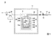
図1は、本発明の実施の形態に係る不純物金属のサンプリング方法を実施する際に使用するサンプリング装置の概略構成を示す系統図であり、サンプリング装置の構成要素のうち、クリーンブース内に配置された構成要素を断面で示した図である。
図2は、図1に示すサンプリング装置の領域Aで囲まれた部分を拡大した断面図であり、サンプリング装置の構成要素のうち、捕集容器、ガス供給ライン、及び液体排気ラインのみを図示した図である。
(Embodiment)
FIG. 1 is a system diagram showing a schematic configuration of a sampling device used when carrying out a method for sampling an impurity metal according to an embodiment of the present invention, and is arranged in a clean booth among components of the sampling device. FIG.
FIG. 2 is an enlarged cross-sectional view of a portion surrounded by the region A of the sampling device shown in FIG. 1, and shows only the collection container, the gas supply line, and the liquid exhaust line among the components of the sampling device. FIG.
始めに、図1及び図2を参照して、本発明の実施の形態に係る不純物金属のサンプリング方法を実施する際に使用するサンプリング装置10について説明する。
サンプリング装置10は、クリーンブース11と、捕集容器13と、ガス供給ライン15と、焼結フィルター17と、減圧弁18と、ストップバルブ19と、ライン用ヒーター22,と、金属製容器24と、容器用ヒーター26と、液体排気ライン28と、冷却トラップ31と、流量計33と、を有する。
First, with reference to FIG. 1 and FIG. 2, the
The
クリーンブース11は、クリーンブース11内の雰囲気をクリーンブース11外の雰囲気と比較して、清浄な状態(ダストが少ない状態)に保つためのものである。クリーンブース11は、クリーンブース11の外からクリーンブース11内にガス供給ライン15を導くための貫通穴(図示せず)と、クリーンブース11外からクリーンブース11の内に液体排気ライン28を導くための貫通穴(図示せず)と、を有する。
The
捕集容器13は、容器本体13Aと、蓋体13Bと、を有する。容器本体13A内には、被分析対象物である不純物金属14B(金属)を含有する液体14Aを含む試料溶液14が収容されている。捕集容器13内の圧力は、大気圧とされている。
The
液体14Aとしては、例えば、沸点が200℃以下の溶液(例えば、水)または液体材料ガスを例示することができる。沸点が200℃以下の液体材料ガスとしては、例えば、テトラエトキシシラン(TEOS)、テトラキスジメチルアミノシラン(4DMAS)、ビステトラブチルアミノシラン(BTBAS)、ジメチルスルホキシド(DMSO)、水等を例示することができる。
Examples of the
蓋体13Bは、ガス供給ライン15を通過させるための第1の貫通穴36と、液体排気ライン28の回収口28Aを通過させるための第2の貫通穴37と、を有する。蓋体13Bは、容器本体13Aの上端に取り付けられている。
The
上記構成とされた捕集容器13としては、例えば、試料溶液14及びその蒸気が接する少なくとも内面に、耐熱性、耐薬品性、及び難燃性に優れたフッ素系樹脂が用いられた容器を用いるとよい。上記フッ素樹脂としては、例えば、260℃程度の耐熱性を有するポリテトラフルオロエチレン (PTFE) や、ポリテトラフルオロエチレン(PFA)等が好ましい。
As the
このように、不純物金属14Bを含有する液体14Aを含む試料溶液14及びその蒸気が接する内面にフッ素系樹脂を用いた捕集容器13を用いることで、液体14Aが高い反応性を有する場合でも捕集容器13が液体14Aと反応することを抑制可能となる。これにより、液体14Aにより、捕集容器13が変形したり、破損したりすることを抑制できる。
In this way, by using the
ガス供給ライン15は、ガス供給源(図示せず)と接続されており、ガス供給源(図示せず)から供給されたガスを吹き付ける吹き出し口15Aを有する。
The
ガス供給ライン15は、クリーンブース11に設けられた貫通穴(図示せず)を介して、クリーンブース11の外からクリーンブース11内に延在すると共に、容器用ヒーター26の蓋体26B、及び蓋体13Bの貫通穴36を介して、捕集容器13内に延在している。
吹き出し口15Aは、ガスの吹き出し方向が試料溶液14の液面に対して垂直となるように配置されている。これにより、捕集容器13内に配置された試料溶液14の蒸発を促進することができる。
The
The
ガス供給源(図示せず)から供給されたガス(例えば、窒素や、ヘリウム、ネオン、及びアルゴン等の希ガス類元素等の不活性ガス)は、焼結フィルター17を通過することで清浄なガスとなり、その後、ガス供給ライン15の吹き出し口15Aを介して、試料溶液14の液面14aに吹き付けられる。
本発明において、「清浄なガス」とは、大気より被分析成分量の少ないガスのことをいう。清浄なガスとしては、例えば、フィルターを通過させた不活性ガスを用いることができる。
Gas supplied from a gas supply source (not shown) (for example, inert gas such as nitrogen, rare gas elements such as helium, neon, and argon) passes through the
In the present invention, “clean gas” refers to a gas having a smaller amount of component to be analyzed than the atmosphere. As the clean gas, for example, an inert gas that has passed through a filter can be used.
吹き出し口15Aと試料溶液14の液面14aとの距離Dが10mm以上で、かつ吹き出し口15Aから吹き出される清浄なガスの流速が0.20〜0.50cm/secの範囲内に設定するとよい。
このような条件で、吹き出し口15Aを介して、試料溶液14の液面14aに清浄なガスを吹き付けることにより、試料溶液14を対流させることが可能となり、試料溶液14の突沸を抑制できると共に、蒸気14Aを清浄なガスに同伴させて捕集容器13外に排出することができる。
The distance D between the
Under such conditions, by blowing clean gas to the
焼結フィルター17は、クリーンブース11外に位置するガス供給ライン15に設けられている。焼結フィルター17は、ガス供給源(図示せず)から供給されたガスに含まれる不純物を除去することで、外気よりも清浄なガスを得るためのフィルターである。
このように、ガスに含まれる不純物を除去するフィルターとして、焼結フィルター17を用いることで、金網フィルターを用いた場合と比較して、より清浄なガスを得ることが可能となる。
The
As described above, by using the
これにより、ガスに含まれる不純物(具体的には、不純物金属)が捕集容器13内に浸入することを抑制可能となるので、不純物金属14Bのみを精度良く捕集することができる。
上記焼結フィルター17としては、例えば、SUS(ステンレス鋼)製の焼結フィルターを用いることができる。
Thereby, since it becomes possible to suppress the impurity (specifically, impurity metal) contained in the gas from entering the
As the
減圧弁18は、クリーンブース11と焼結フィルター17との間に位置するガス供給ライン15に設けられている。減圧弁19は、清浄なガスの圧力を減圧させることで、該ガスの圧力を一定の圧力に保持する。
The
ストップバルブ19は、クリーンブース11と減圧弁18との間に位置するガス供給ライン15に設けられている。
ストップバルブ19は、清浄なガスの流れを止めたり、バルブの開度を調整することで、クリーンブース11内に位置するガス供給ライン15に供給する清浄なガスの流量を調節したりするバルブである。
このように、ガス供給ライン15にストップバルブ19を設けることにより、吹き出し口15Aから吹き出される清浄なガスの流速を所望の流速(具体的には、0.20〜0.50cm/sec)の範囲内に調節することができる。
The
The
Thus, by providing the
ライン用ヒーター22は、クリーンブース11内に位置するガス供給ライン15のうち、蓋体26Bの外側に位置する部分に設けられている。ライン用ヒーター22は、ガス供給ライン15を流れる清浄なガスを液体14Aの沸点よりも低い温度で加熱するためのヒーターである。
The
液体14Aの沸点が200℃の場合、ライン用ヒーター22は、例えば、上記清浄なガスの温度が80〜150℃の範囲内の温度となるように、該清浄なガスを加熱する。
このように、液体14Aの沸点が200℃の場合、ライン用ヒーター22により、清浄なガスの温度が80〜150℃の範囲内の温度となるように加熱することで、清浄なガスの供給を停止させた際、液体14Aの沸点との温度差(この場合、20〜50℃)により、ガス供給ライン15に清浄なガスが逆流することを抑制できる。
When the boiling point of the liquid 14 </ b> A is 200 ° C., the
Thus, when the boiling point of the liquid 14A is 200 ° C., the
このように、捕集容器13内に収容された試料溶液14に吹き付ける前の清浄なガスを加熱するライン用ヒーター22を有することにより、捕集容器13内に清浄なガスを吹き付けた際、捕集容器13内の温度や清浄なガスの温度の低下を抑制可能となる。
これにより、サンプリング装置10を用いて、実施の形態に係る不純物金属のサンプリング方法を実施した際、清浄なガスを加熱しないで液面14aに吹き付けた場合よりも、短時間で不純物金属のサンプリング(捕集)を終了させることができる。ライン用ヒーター22としては、例えば、マントルヒーターを用いることができる。
As described above, when the clean gas is sprayed into the
Thereby, when the sampling method of the impurity metal according to the embodiment is performed using the
金属製容器24は、容器本体13Aの外面を覆うように設けられている。言い換えれば、金属製容器24は、容器本体13Aの外面と接触するように、容器本体13Aを収容している。金属容器24は、捕集容器13の温度の低下を抑制するための容器である。金属容器24の材料としては、例えば、アルミニウムを用いることができる。
The
容器用ヒーター26は、第1の部分26Aと、第2の部分26Bと、を有する。第1の部分26Aは、金属製容器24の外面を覆うように配置されている。第2の部分26Bは、容器本体13Aの外面の一部、及び蓋体13Bを覆うように配置されている。
容器用ヒーター26は、金属製容器24、容器本体13Aの外面の一部、及び蓋体13Bを介して、容器本体13Aに収容された液体14Aの沸点に到達するように、試料溶液14を加熱する。
The
The
液体排気ライン28は、除害装置(図示せず)と接続されており、液体14Aを回収する回収口28Aを有する。
液体排気ライン28は、クリーンブース11に設けられた貫通穴(図示せず)を介して、クリーンブース11の外からクリーンブース11内に延在すると共に、容器用ヒーター26の蓋体26B、及び蓋体13Bの貫通穴37を介して、捕集容器13内に延在することで、回収口28Aが捕集容器13内に配置されている。
The
The
回収口28Aは、吹き出し口15Aよりも上方に配置されている。液体排気ライン28は、吹き出し口15Aから清浄なガスに同伴された蒸発した液体14Aを回収し、その後、冷却トラップ31及び流量計33を経由後、清浄なガスで希釈された液体14Aを除害装置(図示せず)に供給する。
このように、清浄なガスを用いて液体14Aを希釈することで、液体14Aが毒性を有する場合でも安全に液体14Aを除害装置(図示せず)に供給することができる。
The
Thus, by diluting the liquid 14A using a clean gas, the
上記構成とされた液体排気ライン28の材料としては、耐熱性、耐薬品性、及び難燃性に優れたフッ素系樹脂(例えば、260℃程度の耐熱性を有するポリテトラフルオロエチレン (PTFE) や、ポリテトラフルオロエチレン(PFA)等)を用いるとよい。
このように、液体排気ライン28の材料として、フッ素系樹脂を用いることで、試料溶液14に含まれる液体14Aが高い反応性を有する場合でも液体排気ライン28が液体14Aと反応することを抑制できる。
Examples of the material of the
Thus, by using a fluorine-based resin as the material of the
冷却トラップ31は、クリーンブース11の外側に位置する液体排気ライン28に設けられている。冷却トラップ31は、液体排気ライン28により輸送された有害な液体を捕集することで、該有害な液体により、図示していない吸引ポンプなど後段に設けられている設備が破損することを抑制する機能を有する。
The
流量計33は、除害装置(図示せず)と冷却トラップ31との間に位置する液体排気ライン28に設けられている。流量計33は、液体排気ライン28を流れる流体の流速を測定する。
The
次に、図1及び図2を参照して、上記説明したサンプリング装置10を用いた本実施の形態の不純物金属のサンプリング方法について説明する。
始めに、クリーンブース11内において、大気圧とされ、かつ少なくとも内面がフッ素系樹脂よりなる捕集容器13内に、被分析対象物である不純物金属14B(金属)を含有する液体14Aを含む試料溶液14を封入する。
その後、第2の部分26B(容器用ヒーター26の一部)が設けられた蓋体13Bが閉じられる。このとき、液面14aと吹き出し口15Aとの距離Dが10mm以上になるように設定する。
Next, the impurity metal sampling method of the present embodiment using the
First, in the
Thereafter, the
次いで、大気圧下で捕集容器13内の試料溶液14を加熱することにより、液体14Aを蒸発させ、捕集容器13内の不純物金属14Bを含む残渣を回収する(残渣を回収する工程)。
この残渣を回収する工程では、捕集容器13内に位置する吹き出し口15Aから試料溶液14の液面14aに向けて清浄なガスを吹き付けるとともに、捕集容器13内に配置された回収口28Aから試料溶液14の蒸気を含むガスを捕集容器13の外に導出する。
このとき、清浄なガスにより、蒸発する液体14Aを希釈し、希釈された液体14Aを排気させながら、上記残渣を回収する。
Next, by heating the
In the step of collecting the residue, clean gas is blown from the blowing
At this time, the liquid 14A to be evaporated is diluted with a clean gas, and the residue is collected while exhausting the diluted liquid 14A.
具体的には、下記手法により、残渣を回収する工程を行う。
始めに、ライン用ヒーター22の電源をオンして、ガス供給ライン15内を流れる清浄なガスの温度が80〜150℃の範囲内となるようにガス供給ライン15を加熱する。
次いで、ガス供給源(図示せず)から供給されたガス(例えば、不活性ガス)をガス供給ライン15により輸送し、焼結フィルター17を通過させる。これにより、ガスに含まれる不純物(金属も含む)が除去され、外気(クリーンブース11の外の空気)よりも清浄なガスがストップバルブ19に供給される。
Specifically, a step of collecting the residue is performed by the following method.
First, the power supply of the
Next, a gas (for example, inert gas) supplied from a gas supply source (not shown) is transported through the
次いで、ストップバルブ19の開度を調節することでガスの供給量(言い換えれば、吹き出し口15Aから供給される清浄なガスの流速を調節する。
具体的には、吹き出し口15Aから液面14aに吹き付けられる清浄なガスの流速が、0.20〜0.50cm/secの範囲内となるように調節する。また、減圧弁18により、清浄なガスの圧力が所定の圧力となるように調節する。
Next, by adjusting the opening degree of the
Specifically, the flow rate of the clean gas blown from the
これにより、クリーンブース11内に位置するガス供給ライン15に、所定の圧力、及び所定の流速とされた清浄なガスが供給される。
次いで、清浄なガスは、ライン用ヒーター22により、液体14Aの沸点(例えば、200℃)よりも低い温度(例えば、80〜150℃)で加熱される。その後、清浄なガスは、吹き出し口15Aから0.20〜0.50cm/secの範囲内の流速で液面14aに吹き付けられる。
As a result, clean gas having a predetermined pressure and a predetermined flow velocity is supplied to the
Next, the clean gas is heated by the
これにより、試料溶液14を対流させることが可能となるので、試料溶液14の突沸を防ぐことができると共に、液体排気ライン28を介して、捕集容器13外に蒸発した液体14Aを清浄なガスと共に同伴させることができる。
これにより、捕集容器13内に、液体14に含まれていた不純物金属14Bを精度良く残存させることができる。
As a result, the
Thereby, the
液体排気ライン28により、輸送された試料溶液14は、冷却トラップ31により、有害な液体が捕集され、残りが流量計33を介して、除害装置(図示せず)に供給され、除害処理される。
The
本実施の形態の不純物金属のサンプリング方法によれば、少なくとも内面がフッ素系樹脂よりなる捕集容器13内に、不純物金属14Bを含有した液体14Aを含む試料溶液14を封入する工程と、大気圧下で捕集容器13内の試料溶液14を加熱することにより液体14Aを蒸発させ、捕集容器13内の残渣を回収する工程を有し、残渣を回収する工程において、捕集容器13内に位置する吹き出し口15Aから試料溶液14の液面14aに向けて清浄なガスを吹き付けるとともに、捕集容器13内に配置された回収口28Aから試料溶液14の蒸気を含むガスを捕集容器13の外に導出させることにより、液体14Aが高い反応性を有するものであった場合でもサンプリング装置10を構成する捕集容器13及び液体排気ライン28の損傷を抑制した上で、短時間で、かつ精度良く試料溶液14に含まれる不純物金属14Bをサンプリングすることができる。
According to the impurity metal sampling method of the present embodiment, the step of enclosing the
また、前述のサンプリング方法により捕集した不純物金属14Bを含む残渣を、例えば塩酸溶液やフッ酸溶液に溶解し、当該溶液をICP−MS等の分析装置に導入することにより、試料溶液14中の不純物金属14Bを精度よくかつ迅速に分析することができる。
Further, the residue containing the
以上、本発明の好ましい実施の形態について詳述したが、本発明はかかる特定の実施の形態に限定されるものではなく、特許請求の範囲内に記載された本発明の要旨の範囲内において、種々の変形・変更が可能である。 The preferred embodiments of the present invention have been described in detail above, but the present invention is not limited to such specific embodiments, and within the scope of the present invention described in the claims, Various modifications and changes are possible.
(評価試験)
以下、本発明のサンプリング方法の有効性を確認するため、各種液体材料中の金属成分(不純物金属14B)を定量した実験について説明する。
始めに、第1の液体としてテトラエトキシシリコン(TEOS、沸点168.8℃)と、第2の液体として水と、第3の液体としてジメチルスルホキシド(DMSO、沸点189℃)と、を準備した。
また、トレーサビリティーの確保された標準溶液として、SPEX社製の多元素混合標準溶液(型番:XSTC−622)を準備した。
(Evaluation test)
Hereinafter, in order to confirm the effectiveness of the sampling method of the present invention, an experiment in which the metal component (
First, tetraethoxysilicon (TEOS, boiling point 168.8 ° C.) was prepared as the first liquid, water as the second liquid, and dimethyl sulfoxide (DMSO, boiling point 189 ° C.) as the third liquid.
In addition, a multi-element mixed standard solution (model number: XSTC-622) manufactured by SPEX was prepared as a standard solution in which traceability was ensured.
次いで、捕集容器13として、市販されているフッ素系樹脂製容器を3つ準備した。次いで、第1のフッ素系樹脂製容器に5gの第1の液体を分取し、第2のフッ素系樹脂製容器に5gの第2の液体を分取し、第3のフッ素系樹脂製容器に5gの第3の液体を分取した。
Next, three commercially available fluororesin containers were prepared as the
次いで、上記標準溶液を希釈して、最終調整濃度が1μg/Lとされた希釈標準溶液を作成した。次いで、添加回収試験用の検体として希釈標準溶液を、上記3つのフッ素系樹脂製容器(第1ないし第3のフッ素系樹脂製容器)のそれぞれに添加した。
これにより、第1の液体及び希釈標準溶液よりなる第1のサンプル(試料溶液)と、第2の液体及び希釈標準溶液よりなる第2のサンプル(試料溶液)と、第3の液体及び希釈標準溶液よりなる第3のサンプル(試料溶液)と、を作製した。
Next, the standard solution was diluted to prepare a diluted standard solution having a final adjusted concentration of 1 μg / L. Next, a diluted standard solution was added to each of the three fluororesin containers (first to third fluororesin containers) as a specimen for addition recovery test.
Accordingly, the first sample (sample solution) composed of the first liquid and the diluted standard solution, the second sample (sample solution) composed of the second liquid and the diluted standard solution, the third liquid and the diluted standard solution. A third sample (sample solution) made of the solution was prepared.
次いで、図1に示すサンプリング装置10を用いて、各フッ素系樹脂製容器にフッ素樹脂製の液体排気ライン28を取り付け、吹き出し口15Aから各サンプルの表面に、外気よりも清浄なガスである窒素(N2)を吹き付ける場合(この場合、吹き出し口15Aから吹き出される窒素の流速が0.30cm/sec)と、窒素を吹き付けない場合(安全なサンプリングポイント(ドラフト)にて大気開放させた場合)と、各サンプルに窒素をバブリングさせる場合(この場合、窒素の流速が0.3cm/sec)と、について評価を行った。
このとき、各サンプルの液面と吹き出し口15Aとの距離は、10mmとした。
Next, using the
At this time, the distance between the liquid level of each sample and the
以下、外気よりも清浄なガスである窒素(N2)を吹き付ける方法での実験を実施例といい、窒素を吹き付けない方法での実験を比較例1といい、各サンプルに窒素をバブリングさせる方法での実験を比較例2という。 Hereinafter, an experiment with a method of blowing nitrogen (N 2 ), which is a gas cleaner than the outside air, is referred to as an example, and an experiment with a method of not blowing nitrogen is referred to as comparative example 1, and a method of bubbling nitrogen to each sample. This experiment is referred to as Comparative Example 2.
このとき、ライン用ヒーター22としてリボンヒーターを用い、各サンプルに含まれる液体(第1ないし第3の液体のうちのいずれかの液体)の沸点よりも低い温度(具体的には、80〜150℃の範囲内)で、窒素の加熱を行った。
また、容器用ヒーター26としてマントルヒーターを用い、該マントルヒーターにより、捕集容器13の温度が各サンプルに含まれる液体の沸点となるように加熱した。
At this time, a ribbon heater is used as the
In addition, a mantle heater was used as the
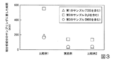
そして、サンプリング処理の完了後、各フッ素系樹脂製容器内に残存する金属残渣を採取した。このときのサンプリング処理に要した時間に関するデータを図3に示す。
図3は、第1ないし第3のサンプルに含まれる被分析成分のサンプリングに要した時間を示す図である。
Then, after the sampling process was completed, the metal residue remaining in each fluororesin container was collected. FIG. 3 shows data relating to the time required for the sampling process at this time.
FIG. 3 is a diagram showing the time required for sampling the components to be analyzed contained in the first to third samples.
次いで、濃度が0.5%とされた塩酸(HCl)溶液を用いて、各フッ素系樹脂製容器内から採取した金属残渣を溶出した。
次いで、金属残渣を溶出した塩酸溶液をアジレント・テクノロジー社製の高周波誘導結合プラズマ質量分析装置(ICP−MS)である7500csに導入し、被分析成分(具体的には、Na、Fe、Cu、Ca、Ni、Zn)の定量を行った。
なお、回収率の測定は第1のサンプル及び第3のサンプルについてのみ実施した。
Next, using a hydrochloric acid (HCl) solution having a concentration of 0.5%, the metal residue collected from each fluorine resin container was eluted.
Next, the hydrochloric acid solution eluting the metal residue was introduced into 7500cs, which is a high frequency inductively coupled plasma mass spectrometer (ICP-MS) manufactured by Agilent Technologies, and the components to be analyzed (specifically, Na, Fe, Cu, Ca, Ni, Zn) was quantified.
The recovery rate was measured only for the first sample and the third sample.
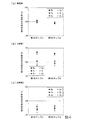
この結果を図4に示す。図4は、第1及び第3のサンプルに含まれる被分析成分の回収率を示す図であり、(a)は実施例の方法による被分析成分の回収率、(b)は比較例1の方法による被分析成分の回収率、(c)は比較例2の方法による被分析成分の回収率をそれぞれ示している。 The result is shown in FIG. FIG. 4 is a diagram showing the recovery rates of the analytes contained in the first and third samples, (a) is the recovery rate of the analytes by the method of the example, and (b) is the comparative example 1. The recovery rate of the component to be analyzed by the method and (c) show the recovery rate of the component to be analyzed by the method of Comparative Example 2, respectively.
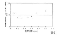
また、上記第1のサンプルを用いて、窒素の流速を0.1〜1.0cm/secの範囲内で変更させることで、被分析成分のサンプリングに要する時間を測定した。この結果を図5に示す。
図5は、窒素の流速と第1のサンプルに含まれる被分析成分のサンプリングに要する時間との関係を示す図である。
Moreover, the time required for sampling of the component to be analyzed was measured by changing the flow rate of nitrogen within the range of 0.1 to 1.0 cm / sec using the first sample. The result is shown in FIG.
FIG. 5 is a diagram showing the relationship between the flow rate of nitrogen and the time required for sampling the component to be analyzed contained in the first sample.
(評価試験の結果について)
図3を参照するに、実施例及び比較例2は、比較例1よりも短時間で液体が蒸発し、被分析成分のサンプリング処理が短時間で完了することが分かった。
図4(a)を参照するに、実施例では、第1及び第3のサンプルのいずれのサンプルを用いた場合でも回収率が100%に近い値となり、良好な結果が得られた。
(Evaluation test results)
Referring to FIG. 3, it was found that in Example and Comparative Example 2, the liquid evaporates in a shorter time than Comparative Example 1, and the sampling process for the component to be analyzed is completed in a shorter time.
Referring to FIG. 4A, in the example, the recovery rate was close to 100% regardless of which of the first and third samples was used, and good results were obtained.
一方、図4(c)を参照するに、比較例2では、第1及び第3のサンプルのいずれのサンプルを用いた場合でも回収率が100%よりもかなり小さい値となった。
このように、比較例2の回収率が100%よりもかなり小さい値になった理由としては、第1及び第3のサンプルにガスを通気させた際にサンプルが飛沫し、本来フッ素系樹脂製容器内に残留するはずだった不純物金属が通気ガスとともにフッ素系樹脂製容器の外に同伴されたことが考えられる。
On the other hand, referring to FIG. 4 (c), in Comparative Example 2, the recovery rate was considerably smaller than 100% in any of the first and third samples.
As described above, the reason why the recovery rate of Comparative Example 2 was considerably smaller than 100% was that when the gas was passed through the first and third samples, the samples splashed and were originally made of a fluororesin. It is considered that the impurity metal that should have remained in the container was entrained outside the fluororesin container together with the ventilation gas.
また、図4(b)を参照するに、比較例1では、NaやCa等の被分析成分の回収率が高い値となった。これは、大気開放の場合、外部から汚染物質が混入したことが考えられる。
上記説明した図4に示す結果から、本発明を適用した実施例の方法を用いることで、サンプル(試料溶液)に含まれる液体が早期に蒸発し、サンプルに含まれる被分析成分のサンプリング処理を簡便に実施することが可能になると共に、分析装置から得られる分析結果も高精度になることが確認できた。
Further, referring to FIG. 4B, in Comparative Example 1, the recovery rate of components to be analyzed such as Na and Ca was a high value. In the case of opening to the atmosphere, this may be due to contamination from the outside.
From the result shown in FIG. 4 described above, by using the method of the embodiment to which the present invention is applied, the liquid contained in the sample (sample solution) evaporates at an early stage, and the sampling process of the component to be analyzed contained in the sample is performed. It was possible to carry out easily, and it was confirmed that the analysis result obtained from the analyzer was also highly accurate.
図5を参照するに、吹き出し口15Aから吹き出される窒素の流速を速くすると、サンプルに含まれる被分析成分のサンプリング処理に要する時間は短くなるが、窒素の流速が0.6cm/sec以上になると、被分析成分のサンプリング処理に要する時間が長くなることが分かった。
Referring to FIG. 5, if the flow rate of nitrogen blown from the
これは、窒素の流速が遅い場合(0.6cm/secよりも小さい場合)には、リボンヒーターによる窒素の加熱が有効に行われ、所望の温度に加熱された窒素ガスが効率良く、サンプルの表面に吹き付けられたためであると考えられる。
但し、窒素の流速が0.1cm/sec以下になると、サンプルの液面に窒素を吹き付ける効果がかなり小さくなり、その結果、被分析成分の捕集に要する時間が長くなったものと考えられる。
This is because when the flow rate of nitrogen is low (less than 0.6 cm / sec), the nitrogen heater is effectively heated by the ribbon heater, and the nitrogen gas heated to a desired temperature is efficiently used. It is thought that it was because it was sprayed on the surface.
However, when the flow rate of nitrogen is 0.1 cm / sec or less, it is considered that the effect of spraying nitrogen on the liquid surface of the sample is considerably reduced, and as a result, the time required for collecting the components to be analyzed is increased.
したがって、上記説明した図5に示す結果から、被分析成分のサンプリングに要する時間を60分以内にする場合、吹き出し口よりサンプルの液面に吹き付ける窒素の流速は、0.20〜0.50cm/secの範囲内が好ましいことが確認できた。 Therefore, from the result shown in FIG. 5 described above, when the time required for sampling the analyte is within 60 minutes, the flow rate of nitrogen blown from the outlet to the liquid surface of the sample is 0.20 to 0.50 cm / It was confirmed that a value within the range of sec was preferable.
本発明は、不純物サンプリング装置の損傷を抑制した上で、短時間で、かつ精度良く、試料溶液に含まれる不純物金属をサンプリング可能な不純物金属のサンプリング方法に適用できる。 The present invention can be applied to an impurity metal sampling method capable of sampling an impurity metal contained in a sample solution in a short time and with high accuracy while suppressing damage to the impurity sampling device.
10…サンプリング装置、11…クリーンブース、13…捕集容器、13A…容器本体、13B…蓋体、14…試料溶液、14a…液面、14A…液体、14B…不純物金属、15…ガス供給ライン、15A…吹き出し口、17…焼結フィルター、18…減圧弁、19…ストップバルブ、22…ライン用ヒーター、24…金属製容器、26…容器用ヒーター、26A…第1の部分、26B…第2の部分、28…液体排気ライン、28A…回収口、31…冷却トラップ、33…流量計、36,37…貫通穴、D…距離
DESCRIPTION OF
Claims (5)
大気圧下で前記捕集容器内の試料溶液を加熱することにより前記液体を蒸発させ、前記捕集容器内の前記金属を含む残渣を回収する工程を有し、
前記残渣を回収する工程において、前記捕集容器内に位置する吹き出し口から前記試料溶液の液面に向けて清浄なガスを吹き付けるとともに、前記捕集容器に設けられた回収口から前記試料溶液の蒸気を含むガスを前記捕集容器の外に導出することを特徴とする不純物金属のサンプリング方法。 Enclosing a sample solution containing a metal-containing liquid in a collection container having at least an inner surface made of a fluororesin;
Heating the sample solution in the collection container under atmospheric pressure to evaporate the liquid and recovering the metal-containing residue in the collection container;
In the step of recovering the residue, a clean gas is blown toward the liquid surface of the sample solution from a blowout port located in the collection container, and the sample solution is discharged from a collection port provided in the collection container. A method for sampling an impurity metal, wherein a gas containing vapor is led out of the collection container.
Priority Applications (1)
| Application Number | Priority Date | Filing Date | Title |
|---|---|---|---|
| JP2013067404A JP2014190873A (en) | 2013-03-27 | 2013-03-27 | Method for sampling impurity metal and method for analyzing metal component in solution |
Applications Claiming Priority (1)
| Application Number | Priority Date | Filing Date | Title |
|---|---|---|---|
| JP2013067404A JP2014190873A (en) | 2013-03-27 | 2013-03-27 | Method for sampling impurity metal and method for analyzing metal component in solution |
Publications (1)
| Publication Number | Publication Date |
|---|---|
| JP2014190873A true JP2014190873A (en) | 2014-10-06 |
Family
ID=51837255
Family Applications (1)
| Application Number | Title | Priority Date | Filing Date |
|---|---|---|---|
| JP2013067404A Pending JP2014190873A (en) | 2013-03-27 | 2013-03-27 | Method for sampling impurity metal and method for analyzing metal component in solution |
Country Status (1)
| Country | Link |
|---|---|
| JP (1) | JP2014190873A (en) |
Cited By (1)
| Publication number | Priority date | Publication date | Assignee | Title |
|---|---|---|---|---|
| CN108548711A (en) * | 2018-03-07 | 2018-09-18 | 江苏师范大学 | A kind of thermal purging capturing device for blood analysis |
Citations (9)
| Publication number | Priority date | Publication date | Assignee | Title |
|---|---|---|---|---|
| JPS6011054U (en) * | 1983-07-04 | 1985-01-25 | 日本電子株式会社 | Drying device for test sample solution |
| JPH10111226A (en) * | 1996-10-07 | 1998-04-28 | Nippon Steel Corp | Solvent removal / concentration method of solution sample and impurity determination method for ultra-trace impurity analysis |
| JPH11337465A (en) * | 1998-05-22 | 1999-12-10 | Moritex Corp | Gas spray type concentrator |
| JP2001153769A (en) * | 1999-11-26 | 2001-06-08 | Olympus Optical Co Ltd | Concentrating apparatus |
| JP2001276501A (en) * | 2000-03-28 | 2001-10-09 | Gl Sciences Inc | Solvent evaporation apparatus |
| JP2002005799A (en) * | 2000-06-20 | 2002-01-09 | Tokuyama Corp | Analysis method for trace metal impurities |
| JP2002202316A (en) * | 2000-11-01 | 2002-07-19 | Jeol Ltd | Analysis system and analysis method |
| JP2003294597A (en) * | 2002-04-04 | 2003-10-15 | Tokuyama Corp | Concentration method of volatile elements |
| JP2012181092A (en) * | 2011-03-01 | 2012-09-20 | Taiyo Nippon Sanso Corp | Heating concentrator, and heating concentration method |
-
2013
- 2013-03-27 JP JP2013067404A patent/JP2014190873A/en active Pending
Patent Citations (9)
| Publication number | Priority date | Publication date | Assignee | Title |
|---|---|---|---|---|
| JPS6011054U (en) * | 1983-07-04 | 1985-01-25 | 日本電子株式会社 | Drying device for test sample solution |
| JPH10111226A (en) * | 1996-10-07 | 1998-04-28 | Nippon Steel Corp | Solvent removal / concentration method of solution sample and impurity determination method for ultra-trace impurity analysis |
| JPH11337465A (en) * | 1998-05-22 | 1999-12-10 | Moritex Corp | Gas spray type concentrator |
| JP2001153769A (en) * | 1999-11-26 | 2001-06-08 | Olympus Optical Co Ltd | Concentrating apparatus |
| JP2001276501A (en) * | 2000-03-28 | 2001-10-09 | Gl Sciences Inc | Solvent evaporation apparatus |
| JP2002005799A (en) * | 2000-06-20 | 2002-01-09 | Tokuyama Corp | Analysis method for trace metal impurities |
| JP2002202316A (en) * | 2000-11-01 | 2002-07-19 | Jeol Ltd | Analysis system and analysis method |
| JP2003294597A (en) * | 2002-04-04 | 2003-10-15 | Tokuyama Corp | Concentration method of volatile elements |
| JP2012181092A (en) * | 2011-03-01 | 2012-09-20 | Taiyo Nippon Sanso Corp | Heating concentrator, and heating concentration method |
Cited By (2)
| Publication number | Priority date | Publication date | Assignee | Title |
|---|---|---|---|---|
| CN108548711A (en) * | 2018-03-07 | 2018-09-18 | 江苏师范大学 | A kind of thermal purging capturing device for blood analysis |
| CN108548711B (en) * | 2018-03-07 | 2020-08-04 | 江苏师范大学 | A thermal purge and trap device for blood analysis |
Similar Documents
| Publication | Publication Date | Title |
|---|---|---|
| Den et al. | Airborne molecular contamination: Recent developments in the understanding and minimization for advanced semiconductor device manufacturing | |
| JP6488294B2 (en) | Mass spectrometer inlet that allows a reduction in average flow | |
| CN107850569B (en) | Analytical equipment for silicon substrates | |
| KR102165770B1 (en) | Calibrated particle analysis apparatus and method | |
| JP2013108759A (en) | Impurity analysis method of hydrofluoric acid solution for semiconductor wafer process, and management method of replacement time of hydrofluoric acid solution | |
| JP6530289B2 (en) | Analysis pretreatment unit | |
| CN106098587B (en) | System and method for monitoring pollutants | |
| US20050208674A1 (en) | Method for analyzing impurities | |
| CN104568535A (en) | VPD sample collection method | |
| JP2014190873A (en) | Method for sampling impurity metal and method for analyzing metal component in solution | |
| JP2002005799A (en) | Analysis method for trace metal impurities | |
| JP4693268B2 (en) | Sample water quality evaluation method | |
| JP2004109072A (en) | Method for analyzing metal impurities in liquid | |
| KR102456011B1 (en) | Etching method of boron-doped p-type silicon wafer, metal contamination evaluation method and manufacturing method | |
| US6923188B2 (en) | Method of sampling contaminants of semiconductor wafer carrier | |
| CN205248242U (en) | A surface corrosion device that before is used for silicon chip surface system appearance | |
| JP4857973B2 (en) | Method for analyzing polishing slurry of silicon wafer | |
| JP4760458B2 (en) | Method for analyzing metal contamination of semiconductor wafer storage container | |
| JP3345121B2 (en) | Method and apparatus for analyzing trace components of solid sample | |
| JP3254631B2 (en) | Trace substance extraction device | |
| JP2005326219A (en) | Analysis sample preparing apparatus, analysis sample preparing method and semiconductor sample analysis method | |
| KR20260031170A (en) | Evaporation pretreatment device and method for trace element analysis | |
| Pfeffer et al. | Enhanced contamination control methods in advanced wafer processing | |
| JP2001141721A (en) | Analysis method for trace metal impurities | |
| TWI692049B (en) | Wafer surface inspection pre-processing device and wafer surface inspection equipment using the same |
Legal Events
| Date | Code | Title | Description |
|---|---|---|---|
| A621 | Written request for application examination |
Free format text: JAPANESE INTERMEDIATE CODE: A621 Effective date: 20151209 |
|
| A977 | Report on retrieval |
Free format text: JAPANESE INTERMEDIATE CODE: A971007 Effective date: 20160920 |
|
| A131 | Notification of reasons for refusal |
Free format text: JAPANESE INTERMEDIATE CODE: A131 Effective date: 20160927 |
|
| A02 | Decision of refusal |
Free format text: JAPANESE INTERMEDIATE CODE: A02 Effective date: 20170321 |