JP2014192582A - Remote controller - Google Patents
Remote controller Download PDFInfo
- Publication number
- JP2014192582A JP2014192582A JP2013064380A JP2013064380A JP2014192582A JP 2014192582 A JP2014192582 A JP 2014192582A JP 2013064380 A JP2013064380 A JP 2013064380A JP 2013064380 A JP2013064380 A JP 2013064380A JP 2014192582 A JP2014192582 A JP 2014192582A
- Authority
- JP
- Japan
- Prior art keywords
- control board
- circuit element
- connector
- remote control
- control device
- Prior art date
- Legal status (The legal status is an assumption and is not a legal conclusion. Google has not performed a legal analysis and makes no representation as to the accuracy of the status listed.)
- Granted
Links
Images




Landscapes
- Insertion, Bundling And Securing Of Wires For Electric Apparatuses (AREA)
- Selective Calling Equipment (AREA)
Abstract
【課題】制御基板に実装されたコネクタに電装線を抜き挿しする際、制御基板に実装された回路素子に電装線が接触することによる回路素子の破損を防止できるリモコン装置を提供する。
【解決手段】リモコン装置は、ケース1と、制御基板5と、コネクタ6と、回路素子7とを有している。ケース1は前面部1aから突出した壁部1cを有している。制御基板5は第1および第2の面5a、5bを貫通するスリット5cが形成されている。コネクタ6は第1の面5aに実装され、第1の面5aに沿う方向に電装線を抜き挿し可能である。回路素子7は第1の面5aに実装されている。壁部1cは、第2の面側からスリット5cに挿入された状態で、第1の面5aから突出し、かつ電装線のコネクタ6からの抜き方向に配置されている。
【選択図】図7Provided is a remote control device capable of preventing damage to a circuit element due to contact of an electrical wire with a circuit element mounted on a control board when an electrical wire is inserted into or removed from a connector mounted on a control board.
A remote controller includes a case, a control board, a connector, and a circuit element. The case 1 has a wall portion 1c protruding from the front surface portion 1a. The control board 5 has slits 5c penetrating the first and second surfaces 5a and 5b. The connector 6 is mounted on the first surface 5a, and an electrical wire can be inserted and removed in a direction along the first surface 5a. The circuit element 7 is mounted on the first surface 5a. The wall portion 1c protrudes from the first surface 5a while being inserted into the slit 5c from the second surface side, and is disposed in the direction in which the electrical wire is removed from the connector 6.
[Selection] Figure 7
Description
本発明はリモコン装置に関するものである。 The present invention relates to a remote control device.
従来、給湯器などでは壁面にリモコン装置が設置されており、このリモコン装置が操作されることによって給湯器などの運転が制御される。このようなリモコン装置は、たとえば特開2008−187069号公報(特許文献1)に開示されている。このような壁面に設置されるリモコン装置においては、リモコン装置のケース内に収容される制御基板の背面側に、電装線接続用のコネクタおよび回路素子としての電解コンデンサが実装されている。たとえば特開2002−345124号公報(特許文献2)にはコネクタと回路素子とが制御基板の背面側に実装されたリモコン装置が開示されている。 Conventionally, in a water heater or the like, a remote controller is installed on a wall surface, and the operation of the water heater or the like is controlled by operating the remote controller. Such a remote control device is disclosed in, for example, Japanese Unexamined Patent Application Publication No. 2008-187069 (Patent Document 1). In such a remote control device installed on the wall surface, a connector for connecting electrical wires and an electrolytic capacitor as a circuit element are mounted on the back side of the control board accommodated in the case of the remote control device. For example, Japanese Patent Laid-Open No. 2002-345124 (Patent Document 2) discloses a remote control device in which a connector and a circuit element are mounted on the back side of a control board.
上記の各公報に記載されたような壁面に設置されるリモコン装置では、施工者およびメンテナンス作業者などが制御基板の背面側に実装されたコネクタに電装線を抜き挿しする際、制御基板の背面側に実装された電解コンデンサに電装線が接触することで電解コンデンサを破損させてしまう虞がある。 In the remote control device installed on the wall surface as described in each of the above-mentioned publications, when the installer and the maintenance worker insert and remove the electrical wires into the connector mounted on the back side of the control board, the back side of the control board There is a risk that the electrolytic capacitor may be damaged when the electric wire comes into contact with the electrolytic capacitor mounted on the side.
本発明は、上記の課題を鑑みてなされたものであり、その目的は、制御基板に実装されたコネクタに電装線を抜き挿しする際、制御基板に実装された回路素子に電装線が接触することによる回路素子の破損を防止できるリモコン装置を提供することである。 The present invention has been made in view of the above-described problems, and its purpose is to contact an electrical wire with a circuit element mounted on the control board when the electrical wire is inserted into or removed from a connector mounted on the control board. It is an object of the present invention to provide a remote control device that can prevent circuit elements from being damaged.
本発明のリモコン装置は、電装線と電気的に接続可能なものであって、ケースと、制御基板と、コネクタと、回路素子とを有している。ケースは前面部を有し、前面部から突出した壁部を有している。制御基板は互いに対向する第1および第2の面を有し、第1および第2の面を貫通するスリットが形成されている。コネクタは制御基板の第1の面に実装され、第1の面に沿う方向に電装線を抜き挿し可能である。回路素子は制御基板の第1の面に実装されている。ケースの壁部は、制御基板の第2の面側からスリットに挿入された状態で、第1の面から突出し、かつ電装線のコネクタからの抜き方向に配置されている。 The remote control device of the present invention can be electrically connected to an electrical wire, and includes a case, a control board, a connector, and a circuit element. The case has a front portion and a wall portion protruding from the front portion. The control board has first and second surfaces facing each other, and a slit penetrating the first and second surfaces is formed. The connector is mounted on the first surface of the control board, and the electrical wires can be inserted and removed in the direction along the first surface. The circuit element is mounted on the first surface of the control board. The wall portion of the case is inserted from the second surface side of the control board into the slit and protrudes from the first surface, and is arranged in the direction in which the electrical wire is removed from the connector.
本発明のリモコン装置によれば、ケースの壁部は制御基板の第2の面側からスリットに挿入された状態で第1の面から突出し、かつ電装線のコネクタからの抜き方向に配置されている。このため、制御基板の第1の面に実装されたコネクタに電装線が抜き挿しされる際、第1の面から突出し電装線のコネクタからの抜き方向に配置された壁部に電装線が接触することで、電装線が回路素子に接触することが妨げられる。これにより、回路素子に電装線が接触することによる回路素子の破損を防止することができる。 According to the remote control device of the present invention, the wall portion of the case protrudes from the first surface in a state of being inserted into the slit from the second surface side of the control board, and is arranged in the direction in which the electrical wire is removed from the connector. Yes. For this reason, when the electrical wire is inserted into and removed from the connector mounted on the first surface of the control board, the electrical wire contacts the wall portion that protrudes from the first surface and is arranged in the direction in which the electrical wire is removed from the connector. By doing so, it is prevented that an electrical wire contacts a circuit element. As a result, the circuit element can be prevented from being damaged due to the contact of the electric wire with the circuit element.
上記のリモコン装置によれば、壁部の第1の面から突出した部分の高さ寸法は、回路素子の制御基板の第1の面からの高さ寸法以上の大きさである。このため、制御基板の第1の面に実装されたコネクタに電装線が抜き挿しされる際、第1の面に沿って電装線が移動すると電装線は回路素子に接触する前に壁部に確実に接触する。これにより、回路素子に電装線が接触することによる回路素子の破損を確実に防止することができる。 According to the remote control device described above, the height dimension of the portion protruding from the first surface of the wall portion is not less than the height dimension of the circuit element from the first surface of the control board. For this reason, when an electrical wire is inserted into and removed from a connector mounted on the first surface of the control board, the electrical wire moves to the wall before contacting the circuit element when the electrical wire moves along the first surface. Contact securely. Thereby, it is possible to reliably prevent the circuit element from being damaged due to the contact of the electric wire with the circuit element.
上記のリモコン装置によれば、壁部は、第2の面側からスリットに挿入されて第1の面から突出した状態で、コネクタよりも回路素子の近くに配置されている。このため、コネクタに電装線が抜き挿しされる際、コネクタに電装線を抜き差ししやすいため、誤って電装線が回路素子に接触することを低減できる。 According to the remote control device described above, the wall portion is disposed closer to the circuit element than the connector in a state where the wall portion is inserted into the slit from the second surface side and protrudes from the first surface. For this reason, when the electrical wire is inserted into and removed from the connector, it is easy to insert and remove the electrical wire from the connector, so that it is possible to reduce the erroneous contact of the electrical wire with the circuit element.
上記のリモコン装置によれば、壁部は、第1の面から突出する方向から見てL形形状を有している。壁部をL形形状にすることで壁部の構造上の強度を高くすることができる。このため、電装線の壁部への接触によって壁部が壊れることを抑制できる。これにより、壊れた壁部を電装線が通過して、回路素子に電装線が接触することを抑制することができる。 According to the above remote control device, the wall portion has an L shape when viewed from the direction protruding from the first surface. By making the wall portion L-shaped, the structural strength of the wall portion can be increased. For this reason, it can suppress that a wall part breaks by the contact to the wall part of an electrical wire. Thereby, it can suppress that an electrical equipment wire passes the broken wall part and an electrical equipment wire contacts a circuit element.
上記のリモコン装置によれば、回路素子はコンデンサである。コンデンサは制御基板の背面側に実装される他の部品よりも比較的高さが大きいため、制御基板の第1の面に実装されたコネクタに電装線を抜き挿しする際、コンデンサに電装線が接触しやすい。コンデンサに電装線が接触することが壁部によって妨げられるため、制御基板の第1の面に実装されたコネクタに電装線が抜き挿しされる際、電装線に接触しやすいコンデンサの破損を防止することができる。したがって、回路素子の破損を防止する効果が大きい。 According to the above remote control device, the circuit element is a capacitor. Since the capacitor is relatively higher in height than other components mounted on the back side of the control board, when connecting / disconnecting the electrical lines to / from the connector mounted on the first surface of the control board, Easy to touch. Since the wall prevents the electric wire from coming into contact with the capacitor, the electric wire is prevented from being damaged when the electric wire is inserted into and removed from the connector mounted on the first surface of the control board. be able to. Therefore, the effect of preventing the circuit element from being damaged is great.
以上説明したように、本発明によれば、制御基板に実装されたコネクタに電装線を抜き挿しする際、制御基板に実装された回路素子に電装線が接触することによる回路素子の破損を防止できる。 As described above, according to the present invention, when an electrical wire is inserted into and removed from a connector mounted on a control board, damage to the circuit element due to contact of the electrical wire with the circuit element mounted on the control board is prevented. it can.
以下、本発明の実施の形態について図に基づいて説明する。
まず、本発明の一実施の形態におけるリモコン装置の構成について説明する。
Hereinafter, embodiments of the present invention will be described with reference to the drawings.
First, the configuration of the remote control device according to an embodiment of the present invention will be described.
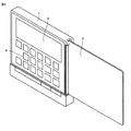
図1を参照して、本発明の一実施の形態におけるリモコン装置は、たとえば給湯器を操作するためのものであり、室内の壁面に取り付けられて、給湯器の制御装置と電装線で接続された状態で使用される。つまり、リモコン装置は電装線と電気的に接続可能であり、電装線によって給湯器と電気的に接続可能である。 Referring to FIG. 1, a remote control device according to an embodiment of the present invention is for operating a water heater, for example, and is attached to a wall surface of a room and connected to a control device of the water heater by an electrical line. Used in the state. That is, the remote control device can be electrically connected to the electrical wire, and can be electrically connected to the water heater by the electrical wire.
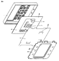
図2〜図4を参照して、本発明の一実施の形態のリモコン装置は、ケース1と、カバー2と、表示部3と、スイッチ4と、制御基板5と、コネクタ6と、回路素子7と、絶縁シート8と、取付板9とを主に有している。
2 to 4, a remote control device according to an embodiment of the present invention includes a case 1, a
リモコン装置の幅方向においてケース1の一方端部にカバー2の一方端部が軸回りに開閉可能に連結されている。ケース1およびカバー2はたとえばABS樹脂などの樹脂材によって形成されている。ケース1の表面側に表示部3と、スイッチ4とが配置されている。カバー2が開いた状態で表示部3とスイッチ4とがカバー2の内側から現れる。なお、カバー2に覆われていない一部のスイッチ4については、カバーが閉じた状態でも操作することが可能である。なお、図1に示すようにカバー2が閉じた状態で表示部3とスイッチ4とはカバー2によって覆われている。
One end of the
ケース1の背面側から制御基板5、絶縁シート8、取付板9の順に、ケース1の内側に制御基板5、絶縁シート8、取付板9が取り付けられている。制御基板5は互いに対向する第1の面5aと第2の面5bとを有しており、リモコン装置の背面側に第1の面5aが配置されており、リモコン装置の前面側に第2の面5bが配置されている。制御基板5の第1の面5aにコネクタ6および回路素子7が実装されている。
The
絶縁シート8は、絶縁性を有する材料で形成されており、たとえばポリエチレン樹脂などの樹脂材によって形成されている。絶縁シート8は、可撓性を有する材料によってシート状に形成されている。絶縁シート8は、コネクタ6を透視しながら電装線を挿抜するために透明または半透明の樹脂材で形成されていることが好ましい。絶縁シート8は、コネクタ6の挿し込み口の手前近傍に相当する個所に、電装線の先端の挿入部を挿入する開口部を形成するための舌片部8aを有している。
The insulating sheet 8 is made of an insulating material, and is made of, for example, a resin material such as polyethylene resin. The insulating sheet 8 is formed in a sheet shape from a flexible material. The insulating sheet 8 is preferably formed of a transparent or translucent resin material in order to insert and remove the electrical wires while seeing through the
取付板9は、板状に形成されており、たとえば鋼によって形成されている。取付板9は中央に開口部9aを有している。この開口部9aを覆うように絶縁シート8がケース1に取り付けられており、この状態で絶縁シート8の舌片部8aによって形成された開口部を通って電装線がコネクタ6に接続される。この取付板9は室内の壁面にねじなどによって取り付けられる。そして、取付板9が壁面に取り付けられた後に、取付板9にケース1を装着することによって、リモコン装置が室内の壁面に取り付けられる。
The mounting plate 9 is formed in a plate shape, and is formed of steel, for example. The mounting plate 9 has an opening 9a in the center. An insulating sheet 8 is attached to the case 1 so as to cover the opening 9 a, and in this state, the electrical wire is connected to the
図5を参照して、ケース1の構成についてさらに詳しく説明する。ケース1は、前面部1aと、側面部1bと、複数の壁部1cとを主に有している。
With reference to FIG. 5, the configuration of case 1 will be described in more detail. The case 1 mainly has a front surface portion 1a, a
前面部1aは、リモコン装置の前面を構成する部材である。前面部1aは板状に形成されている。前面部1aは、表示部3が配置される開口部1d、スイッチ4が配置される押圧部1eを有している。
Front part 1a is a member constituting the front face of the remote control device. The front part 1a is formed in a plate shape. The front part 1a has an opening 1d in which the display part 3 is arranged and a
側面部1bはリモコン装置の側面を構成する部材である。側面部1bは前面部1aの外周端部に配置されており、リモコン装置の背面側に延びるように形成されている。前面部1aと側面部1bとで取り囲まれた領域がケース1の内部空間を構成している。
The
壁部1cは電装線と回路素子7との接触を防ぐための部材である。複数の壁部1cはそれぞれ前面部1aの中央部に形成されている。各壁部1cは前面部1aからリモコン装置の背面側に突出するように形成されている。各壁部1cは前面部1aから突出する方向から見てL形形状を有している。つまり、各壁部1cは前面部1aから突出する方向からみて屈曲している。
The
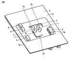
続いて、図6を参照して、制御基板5の構成についてさらに詳しく説明する。制御基板5には、第1の面5aおよび第2の面5bを貫通する複数のスリット5cが形成されている。複数のスリット5cはそれぞれ制御基板5の中央部に形成されている。各スリット5cは第1の面5aおよび第2の面5bを貫通する方向からみてL形形状を有している。各スリット5cは各壁部1cを挿入可能に形成されている。
Next, the configuration of the
制御基板5の第1の面5aに複数のコネクタ6が実装されている。各コネクタは、たとえば給湯器の制御装置に接続された電装線と接続される。各コネクタ6は第1の面5aに沿う方向に電装線を抜き挿し可能に構成されている。つまり、各コネクタ6の挿し込み口6aは第1の面5aに沿う方向に開口している。各コネクタ6は制御基板5の一方端側に配置されており、各コネクタ6の挿し込み口6aは制御基板5の他方端側に向かって開口している。複数のコネクタ6は複数のスリット5cよりも制御基板5の外周側(外側)に配置されている。
A plurality of
また、制御基板5の第1の面5aに複数の回路素子7が実装されている。複数の回路素子7は第1の面5aからリモコン装置の背面側に突出するように取り付けられている。複数の回路素子7は制御基板5の中央部に実装されている。複数の回路素子7は複数のスリット5cよりも制御基板5の中央部側(内側)に配置されている。本発明の一実施の形態では、回路素子7はコンデンサである。
A plurality of
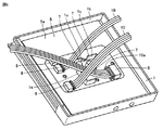
続いて、上記のケース1の内側に制御基板5が取り付けられた状態について説明する。図7および図8を参照して、この状態では、ケース1の内部空間に制御基板5が収容されている。そして、制御基板5の第2の面側から各スリット5cにケース1の各壁部1cがそれぞれ挿入されている。各壁部1cは制御基板5の各スリット5cのそれぞれを通って第1の面5aからケース1の背面側に突出している。壁部1cは電装線10のコネクタ6からの抜き方向に配置されている。
Next, a state where the
壁部1cは電装線10のコネクタ6からの抜き方向と交差する方向に延びる延在部を有している。この延在部はコネクタ6と回路素子7との間に配置されている。壁部1cはコネクタ6の挿し込み口と対向する部分を有している。
The
壁部1cは、第2の面側からスリット5cに挿入されて第1の面5aから突出した状態で、コネクタ6よりも回路素子7の近くに配置されている。つまり、壁部1cは、前面部1aから突出する方向から見てコネクタ6よりも回路素子7の側に配置されている。
The
また、壁部1cは前面部1aから突出する方向から見てL形形状に形成されているため、回路素子7は壁部1cによって互いに交差する2方向から囲まれている。
Further, since the
なお、壁部1cはすべてのコネクタ6に対応して設けられている必要はなく、壁部1cは1つのコネクタ6に対応して設けられていればよい。
The
また、電装線10の先端には挿入部10aが設けられている。この挿入部10aがコネクタ6の挿し込み口に挿入されて電装線10がコネクタ6に接続される。この挿入部10aは第1の面5aに沿ってコネクタ6に抜き挿しされる。
Further, an
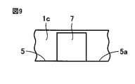
図9を参照して、壁部1cの第1の面5aから突出した部分の高さ寸法は、回路素子7の制御基板5の第1の面5aからの高さ寸法以上の大きさである。これにより、電装線が壁部1cを超えて回路素子7に接触することを防止できる。なお、壁部1cの第1の面5aから突出した部分の高さ寸法は、回路素子7の制御基板5の第1の面5aからの高さ寸法よりも小さくてもよい。この場合でも、壁部1cによって電装線が回路素子7に接触することを防止できる。
Referring to FIG. 9, the height dimension of the portion protruding from the
次に、本発明の一実施の形態におけるリモコン装置の作用効果について比較例と対比して説明する。 Next, the operation and effect of the remote control device according to one embodiment of the present invention will be described in comparison with a comparative example.
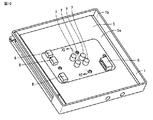
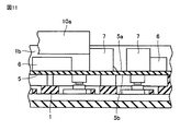
図10および図11を参照して、比較例におけるリモコン装置は、本発明の一実施の形態のリモコン装置とケース1に壁部が形成されていない点で主に異なっている。このため、図11に示すように、制御基板5の第1の面5aに実装されたコネクタ6に電装線の先端の挿入部10aを抜き挿しする際、挿入部10aまたは電装線が回路素子7に接触して回路素子7に外力が加わって回路素子7が破損する虞がある。
Referring to FIG. 10 and FIG. 11, the remote control device in the comparative example is mainly different from the remote control device according to the embodiment of the present invention in that a wall portion is not formed on case 1. For this reason, as shown in FIG. 11, when the
一方、本発明の一実施の形態のリモコン装置によれば、図7および図8に示すように、ケース1の壁部1cは制御基板5の第2の面側からスリット5cに挿入された状態で第1の面5aから突出し、かつ電装線10のコネクタ6からの抜き方向に配置されている。このため、制御基板5の第1の面5aに実装されたコネクタ6に電装線10が抜き挿しされる際、第1の面5aから突出し電装線10のコネクタ6からの抜き方向に配置された壁部1cに電装線10が接触することで、電装線10が回路素子7に接触することが妨げられる。これにより、回路素子7に電装線10が接触することによる回路素子7の破損を防止することができる。つまり、電装線10が壁部1cに接触するため、電装線10が回路素子7に接触して回路素子7に外力が加わることが妨げられる。したがって、電装線10が回路素子7にぶつかったり引っかかったりすることによって外力が加わることが壁部1cによって回避される。
On the other hand, according to the remote control device of one embodiment of the present invention, the
また、ケース1に壁部1cを設けることで、壁部1cをたとえば制御基板5上に別途形成する場合と比べて、部品点数を少なくすることができる。このため、生産コストを低くすることができ、また生産工程を簡略化することもできる。よって、リモコン装置の生産効率を向上することができる。
Also, by providing the case 1 with the
さらに、制御基板5の第1の面5aにコネクタ6と回路素子7とを実装することで、第1の面5aにコネクタ6を実装し、第2の面5bに回路素子7を実装する場合と比べて、制御基板5にコネクタ6および回路素子7が実装された組立体の制御基板5の厚さ方向の寸法を小型化することができる。これにより、ケース1の厚さ方向の寸法も小型化するこができる。よって、リモコン装置を小型化することができる。
Further, when the
本発明の一実施の形態のリモコン装置によれば、図8および図9に示すように、壁部1cの第1の面5aから突出した部分の高さ寸法は、回路素子7の制御基板5の第1の面5aからの高さ寸法以上の大きさである。このため、制御基板5の第1の面5aに実装されたコネクタ6に電装線10が抜き挿しされる際、第1の面5aに沿って電装線10が移動すると電装線10は回路素子7に接触する前に壁部1cに確実に接触する。これにより、回路素子7に電装線10が接触することによる回路素子7の破損を確実に防止することができる。
According to the remote control device of one embodiment of the present invention, as shown in FIGS. 8 and 9, the height dimension of the portion protruding from the
本発明の一実施の形態のリモコン装置によれば、図7および図8に示すように、壁部1cは、第2の面側からスリット5cに挿入されて第1の面5aから突出した状態で、コネクタ6よりも回路素子7の近くに配置されている。このため、コネクタ6に電装線10が抜き挿しされる際、コネクタ6に電装線10を抜き差ししやすいため、誤って電装線10が回路素子7に接触することを低減できる。
According to the remote control device of one embodiment of the present invention, as shown in FIGS. 7 and 8, the
本発明の一実施の形態のリモコン装置によれば、図7および図8に示すように、壁部1cは、第1の面5aから突出する方向から見てL形形状を有している。このように壁部1cをL形形状にすることで壁部1cの構造上の強度を高くすることができる。このため、電装線10の壁部1cへの接触によって壁部1cが壊れることを抑制できる。これにより、壊れた壁部1cを電装線10が通過して、回路素子7に電装線10が接触することを抑制することができる。
According to the remote control device of one embodiment of the present invention, as shown in FIGS. 7 and 8, the
本発明の一実施の形態のリモコン装置によれば、図7および図8に示すように、回路素子7はコンデンサである。コンデンサは制御基板5の背面側に実装される他の部品よりも比較的高さが大きいため、制御基板5の第1の面5aに実装されたコネクタ6に電装線10を抜き挿しする際、コンデンサに電装線10が接触しやすい。コンデンサに電装線10が接触することが壁部1cによって妨げられるため、制御基板5の第1の面5aに実装されたコネクタ6に電装線10が抜き挿しされる際、電装線10に接触しやすいコンデンサの破損を防止することができる。したがって、回路素子7がコンデンサである場合には、回路素子7の破損を防止する効果が大きくなる。
According to the remote control device of one embodiment of the present invention, as shown in FIGS. 7 and 8, the
今回開示された実施の形態はすべての点で例示であって制限的なものではないと考えられるべきである。本発明の範囲は上記した説明ではなくて特許請求の範囲によって示され、特許請求の範囲と均等の意味および範囲内でのすべての変更が含まれることが意図される。 The embodiment disclosed this time should be considered as illustrative in all points and not restrictive. The scope of the present invention is defined by the terms of the claims, rather than the description above, and is intended to include any modifications within the scope and meaning equivalent to the terms of the claims.
1 ケース、1a 前面部、1b 側面部、1c 壁部、2 カバー、3 表示部、4 スイッチ、5 制御基板、5a 第1の面、5b 第2の面、5c スリット、6 コネクタ、6a 挿し込み口、7 回路素子、8 絶縁シート、8a 舌片部、9 取付板、10 電装線、10a 挿入部。 1 Case, 1a Front part, 1b Side part, 1c Wall part, 2 Cover, 3 Display part, 4 Switch, 5 Control board, 5a 1st surface, 5b 2nd surface, 5c Slit, 6 Connector, 6a Insertion Port, 7 Circuit element, 8 Insulating sheet, 8a Tongue piece, 9 Mounting plate, 10 Electrical wire, 10a Insertion part.
Claims (5)
前面部を有し、前記前面部から突出した壁部を有するケースと、
互いに対向する第1および第2の面を有し、前記第1および第2の面を貫通するスリットが形成された制御基板と、
前記制御基板の前記第1の面に実装され、前記第1の面に沿う方向に前記電装線を抜き挿し可能なコネクタと、
前記制御基板の前記第1の面に実装された回路素子とを備え、
前記ケースの前記壁部は、前記制御基板の前記第2の面側から前記スリットに挿入された状態で、前記第1の面から突出し、かつ前記電装線の前記コネクタからの抜き方向に配置されている、リモコン装置。 A remote control device that can be electrically connected to an electrical wire,
A case having a front surface and having a wall protruding from the front surface;
A control board having first and second surfaces facing each other and having slits formed through the first and second surfaces;
A connector mounted on the first surface of the control board and capable of inserting and removing the electrical wires in a direction along the first surface;
A circuit element mounted on the first surface of the control board,
The wall portion of the case protrudes from the first surface in a state where the wall portion is inserted into the slit from the second surface side of the control board, and is arranged in a direction in which the electrical wire is removed from the connector. Remote control device.
Priority Applications (1)
| Application Number | Priority Date | Filing Date | Title |
|---|---|---|---|
| JP2013064380A JP6175836B2 (en) | 2013-03-26 | 2013-03-26 | Remote control device |
Applications Claiming Priority (1)
| Application Number | Priority Date | Filing Date | Title |
|---|---|---|---|
| JP2013064380A JP6175836B2 (en) | 2013-03-26 | 2013-03-26 | Remote control device |
Publications (2)
| Publication Number | Publication Date |
|---|---|
| JP2014192582A true JP2014192582A (en) | 2014-10-06 |
| JP6175836B2 JP6175836B2 (en) | 2017-08-09 |
Family
ID=51838512
Family Applications (1)
| Application Number | Title | Priority Date | Filing Date |
|---|---|---|---|
| JP2013064380A Expired - Fee Related JP6175836B2 (en) | 2013-03-26 | 2013-03-26 | Remote control device |
Country Status (1)
| Country | Link |
|---|---|
| JP (1) | JP6175836B2 (en) |
Citations (4)
| Publication number | Priority date | Publication date | Assignee | Title |
|---|---|---|---|---|
| JPH03250781A (en) * | 1990-02-28 | 1991-11-08 | Toshiba Lighting & Technol Corp | Circuit component mounting structure |
| JP2002345124A (en) * | 2001-05-14 | 2002-11-29 | Noritz Corp | Connection structure of connector |
| JP2004063699A (en) * | 2002-07-26 | 2004-02-26 | Matsushita Electric Works Ltd | Electric equipment |
| JP2011071051A (en) * | 2009-09-28 | 2011-04-07 | Noritz Corp | Operating device |
-
2013
- 2013-03-26 JP JP2013064380A patent/JP6175836B2/en not_active Expired - Fee Related
Patent Citations (4)
| Publication number | Priority date | Publication date | Assignee | Title |
|---|---|---|---|---|
| JPH03250781A (en) * | 1990-02-28 | 1991-11-08 | Toshiba Lighting & Technol Corp | Circuit component mounting structure |
| JP2002345124A (en) * | 2001-05-14 | 2002-11-29 | Noritz Corp | Connection structure of connector |
| JP2004063699A (en) * | 2002-07-26 | 2004-02-26 | Matsushita Electric Works Ltd | Electric equipment |
| JP2011071051A (en) * | 2009-09-28 | 2011-04-07 | Noritz Corp | Operating device |
Also Published As
| Publication number | Publication date |
|---|---|
| JP6175836B2 (en) | 2017-08-09 |
Similar Documents
| Publication | Publication Date | Title |
|---|---|---|
| JP5887326B2 (en) | connector | |
| JP6074711B2 (en) | Cable holding member, electrical connection device, connector device | |
| JP6404248B2 (en) | connector | |
| JP6279989B2 (en) | connector | |
| JP2009016138A (en) | Electrical connector | |
| JP6039511B2 (en) | connector | |
| JP7094640B2 (en) | connector | |
| WO2017038877A1 (en) | Substrate connection structure | |
| JP6175836B2 (en) | Remote control device | |
| WO2017038876A1 (en) | Electrical connector | |
| US8172584B2 (en) | Electrical connection mechanism for connecting an electrical part to a junction box | |
| JP2009224086A (en) | Connector | |
| JP6275544B2 (en) | Terminal fixing structure and circuit breaker | |
| JP6086006B2 (en) | Remote control device | |
| EP3050757A1 (en) | Protector and busbar module and assembling/producing methods therefor | |
| TWI883574B (en) | Locking mechanism and connector assembly | |
| JP6868516B2 (en) | refrigerator | |
| JP5949338B2 (en) | Remote controller | |
| JP6100430B2 (en) | Board connection structure | |
| JP5334655B2 (en) | Crimp terminal and mounting structure of crimp terminal | |
| JP5845519B2 (en) | Electrical equipment with substrate | |
| JP5685997B2 (en) | Circuit board for electrical junction box | |
| JP2015023017A (en) | Connector | |
| JP2018042394A (en) | Protector and electric wire with protector | |
| JP6065522B2 (en) | Remote control device |
Legal Events
| Date | Code | Title | Description |
|---|---|---|---|
| A621 | Written request for application examination |
Free format text: JAPANESE INTERMEDIATE CODE: A621 Effective date: 20160229 |
|
| A977 | Report on retrieval |
Free format text: JAPANESE INTERMEDIATE CODE: A971007 Effective date: 20161212 |
|
| A131 | Notification of reasons for refusal |
Free format text: JAPANESE INTERMEDIATE CODE: A131 Effective date: 20161220 |
|
| A521 | Request for written amendment filed |
Free format text: JAPANESE INTERMEDIATE CODE: A523 Effective date: 20170124 |
|
| TRDD | Decision of grant or rejection written | ||
| A01 | Written decision to grant a patent or to grant a registration (utility model) |
Free format text: JAPANESE INTERMEDIATE CODE: A01 Effective date: 20170613 |
|
| A61 | First payment of annual fees (during grant procedure) |
Free format text: JAPANESE INTERMEDIATE CODE: A61 Effective date: 20170626 |
|
| R150 | Certificate of patent or registration of utility model |
Ref document number: 6175836 Country of ref document: JP Free format text: JAPANESE INTERMEDIATE CODE: R150 |
|
| R250 | Receipt of annual fees |
Free format text: JAPANESE INTERMEDIATE CODE: R250 |
|
| LAPS | Cancellation because of no payment of annual fees |