JP2014193231A - Method of manufacturing vehicle seat - Google Patents
Method of manufacturing vehicle seat Download PDFInfo
- Publication number
- JP2014193231A JP2014193231A JP2013070919A JP2013070919A JP2014193231A JP 2014193231 A JP2014193231 A JP 2014193231A JP 2013070919 A JP2013070919 A JP 2013070919A JP 2013070919 A JP2013070919 A JP 2013070919A JP 2014193231 A JP2014193231 A JP 2014193231A
- Authority
- JP
- Japan
- Prior art keywords
- back surface
- seat
- seat pad
- surface material
- mold
- Prior art date
- Legal status (The legal status is an assumption and is not a legal conclusion. Google has not performed a legal analysis and makes no representation as to the accuracy of the status listed.)
- Granted
Links
Images



Classifications
-
- B—PERFORMING OPERATIONS; TRANSPORTING
- B29—WORKING OF PLASTICS; WORKING OF SUBSTANCES IN A PLASTIC STATE IN GENERAL
- B29C—SHAPING OR JOINING OF PLASTICS; SHAPING OF MATERIAL IN A PLASTIC STATE, NOT OTHERWISE PROVIDED FOR; AFTER-TREATMENT OF THE SHAPED PRODUCTS, e.g. REPAIRING
- B29C44/00—Shaping by internal pressure generated in the material, e.g. swelling or foaming ; Producing porous or cellular expanded plastics articles
- B29C44/02—Shaping by internal pressure generated in the material, e.g. swelling or foaming ; Producing porous or cellular expanded plastics articles for articles of definite length, i.e. discrete articles
- B29C44/12—Incorporating or moulding on preformed parts, e.g. inserts or reinforcements
- B29C44/1228—Joining preformed parts by the expanding material
- B29C44/1233—Joining preformed parts by the expanding material the preformed parts being supported during expanding
-
- B—PERFORMING OPERATIONS; TRANSPORTING
- B60—VEHICLES IN GENERAL
- B60N—SEATS SPECIALLY ADAPTED FOR VEHICLES; VEHICLE PASSENGER ACCOMMODATION NOT OTHERWISE PROVIDED FOR
- B60N2/00—Seats specially adapted for vehicles; Arrangement or mounting of seats in vehicles
- B60N2/58—Seat coverings
- B60N2/5816—Seat coverings attachments thereof
- B60N2/5875—Seat coverings attachments thereof by adhesion, e.g. gluing
-
- B—PERFORMING OPERATIONS; TRANSPORTING
- B60—VEHICLES IN GENERAL
- B60N—SEATS SPECIALLY ADAPTED FOR VEHICLES; VEHICLE PASSENGER ACCOMMODATION NOT OTHERWISE PROVIDED FOR
- B60N2/00—Seats specially adapted for vehicles; Arrangement or mounting of seats in vehicles
- B60N2/70—Upholstery springs ; Upholstery
- B60N2/7017—Upholstery springs ; Upholstery characterised by the manufacturing process; manufacturing upholstery or upholstery springs not otherwise provided for
-
- B—PERFORMING OPERATIONS; TRANSPORTING
- B29—WORKING OF PLASTICS; WORKING OF SUBSTANCES IN A PLASTIC STATE IN GENERAL
- B29C—SHAPING OR JOINING OF PLASTICS; SHAPING OF MATERIAL IN A PLASTIC STATE, NOT OTHERWISE PROVIDED FOR; AFTER-TREATMENT OF THE SHAPED PRODUCTS, e.g. REPAIRING
- B29C44/00—Shaping by internal pressure generated in the material, e.g. swelling or foaming ; Producing porous or cellular expanded plastics articles
- B29C44/02—Shaping by internal pressure generated in the material, e.g. swelling or foaming ; Producing porous or cellular expanded plastics articles for articles of definite length, i.e. discrete articles
- B29C44/12—Incorporating or moulding on preformed parts, e.g. inserts or reinforcements
- B29C44/14—Incorporating or moulding on preformed parts, e.g. inserts or reinforcements the preformed part being a lining
Landscapes
- Engineering & Computer Science (AREA)
- Aviation & Aerospace Engineering (AREA)
- Transportation (AREA)
- Mechanical Engineering (AREA)
- Manufacturing & Machinery (AREA)
- Casting Or Compression Moulding Of Plastics Or The Like (AREA)
Abstract
【課題】シートパッドと裏面材とが一体成形されているシートパッド構造体を製造する際に必要箇所に裏面材を配置することを可能とすること。
【解決手段】シートパッド4と、裏面材5と、を備えるシートパッド構造体を有する乗物用シートの製造方法であって、前記シートパッド4と前記裏面材5とは、複数の分割体で構成される成形型10において一体成形されており、前記分割体同士を重ねあわることにより形成されるパーティングラインPLの少なくとも一部を跨ぐように裏面材5が配置された状態で、前記シートパッド4と前記裏面材5とが一体成形されるものとする。
【選択図】図4An object of the present invention is to make it possible to dispose a back surface material at a necessary position when manufacturing a seat pad structure in which a seat pad and a back surface material are integrally formed.
A method of manufacturing a vehicle seat having a seat pad structure including a seat pad (4) and a back material (5), wherein the seat pad (4) and the back material (5) are constituted by a plurality of divided bodies. In the state where the back material 5 is disposed so as to straddle at least part of the parting line PL formed by overlapping the divided bodies, the seat pad 4 and the back material 5 are integrally formed.
[Selection] Figure 4
Description
本発明は、乗物用シートに関する。詳しくは、裏面材を備える乗物用シートの製造方法に関する。 The present invention relates to a vehicle seat. In detail, it is related with the manufacturing method of the vehicle seat provided with a back material.
従来から、シートフレームとシートパッドを備える乗物用シートが知られている。当該シートパッドがシートフレームと接する側の面には、裏面材といわれる補強用の部材を配置することも知られている(特許文献1参照)。当該裏面材は、シートフレームとの干渉時に発生する異音を防止したり、シートの剛性を高めたりする役割を担っている。
一般的に、このような裏面材は成形型の分割体の重ね合わせ部(パーティングライン)から5mm程度控えた部分に裏面材の端部を配置するように構成している。なぜなら、裏面材がパーティングラインを形成する部分にはまり込むことにより分割体同士が十分に密着せず、そこから樹脂などが漏れ出すような事象が発生することを懸念していたからである。その結果、図6に示すように、シートフレーム8に隣接するような場所においても裏面材5が非連続的に配置される場合があった。
Conventionally, a vehicle seat including a seat frame and a seat pad is known. It is also known that a reinforcing member called a back material is disposed on the surface of the seat pad in contact with the seat frame (see Patent Document 1). The back surface material plays a role of preventing abnormal noise generated at the time of interference with the seat frame and increasing the rigidity of the seat.
In general, such a back material is configured such that the end of the back material is arranged in a portion about 5 mm away from the overlapping portion (parting line) of the divided parts of the mold. This is because there is a concern that an event may occur in which the divided members do not sufficiently adhere to each other due to the back surface material fitting into the part forming the parting line, and the resin or the like leaks therefrom. As a result, as shown in FIG. 6, the
しかしながら、当該構成であると、裏面材を設けることができない箇所においては、シートパッドとシートフレームなどが直に接する可能性があり、異音が発生する恐れがあった。また、裏面材はシートパッドの剛性を高めるためのものでもあるため、裏面材が無い部分は、裏面材がある部分に比べて脆弱な構成となるが、裏面材が無い部分に過大な荷重がかかる場合、予定外にシートパッドが割ける恐れもあった。 However, with this configuration, there is a possibility that the seat pad and the seat frame may be in direct contact with each other at locations where the back material cannot be provided, and there is a possibility that abnormal noise may occur. In addition, since the back material is also used to increase the rigidity of the seat pad, the portion without the back material is more fragile than the portion with the back material, but an excessive load is applied to the portion without the back material. In such a case, the seat pad could be broken unexpectedly.
本発明は、上記した点に鑑みて創案されたものであって、本発明が解決しようとする課題は、シートパッドと裏面材とが一体成形されているシートパッド構造体を製造する際に必要箇所に裏面材を配置することを可能とすることである。 The present invention was devised in view of the above points, and the problem to be solved by the present invention is necessary when manufacturing a seat pad structure in which a seat pad and a back material are integrally formed. It is possible to arrange the backside material at the location.
上記課題を解決するために、本発明は次の手段をとる。
先ず、第1の発明は、シートパッドと、裏面材と、を備えるシートパッド構造体を有する乗物用シートの製造方法であって、前記シートパッドと前記裏面材とは、複数の分割体で構成される成形型において一体成形されており、前記分割体同士を重ねあわせることにより形成されるパーティングラインの少なくとも一部を跨ぐように裏面材が配置された状態で、前記シートパッドと前記裏面材とが一体成形されることを特徴とする。
In order to solve the above problems, the present invention takes the following means.
First, 1st invention is a manufacturing method of the sheet | seat for vehicles which has a seat pad structure provided with a seat pad and a back surface material, Comprising: The said seat pad and the said back surface material are comprised with several division body. The seat pad and the back surface material are integrally formed in the forming mold and the back surface material is disposed so as to straddle at least part of the parting line formed by overlapping the divided bodies. And are integrally molded.
この第1の発明によれば、シートパッドと、裏面材と、を備えるシートパッド構造体を有する乗物用シートの製造方法であって、前記シートパッドと前記裏面材とは、複数の分割体で構成される成形型において一体成形されており、前記分割体同士を重ねあわせることにより形成されるパーティングラインの少なくとも一部を跨ぐように裏面材が配置された状態で、前記シートパッドと前記裏面材とが一体成形されるため、裏面材の配置の自由度があがる。また、成形型のパーティングラインと対向する位置に裏面材が配置された状態となるため、パーティングラインに発泡体が侵入しにくくなる。 According to the first aspect of the present invention, there is provided a vehicle seat manufacturing method including a seat pad structure including a seat pad and a back surface material, wherein the seat pad and the back surface material are a plurality of divided bodies. The seat pad and the back surface are formed integrally in a configured mold and the back pad is disposed so as to straddle at least part of the parting line formed by overlapping the divided bodies. Since the material is integrally formed, the degree of freedom of arrangement of the back surface material is increased. Further, since the back surface material is disposed at a position facing the parting line of the mold, it is difficult for the foam to enter the parting line.
第2の発明は、第1の発明において、複数の分割体が組み合わされることで構成される成形型の第1の分割体に対して第1の裏面材を配置し、前記成形型の第2の分割体に対して第2の裏面材を配置し、前記第1の分割体と前記第2の分割体を組み合わせることで、前記第1の裏面材の一部と前記第2の裏面材の一部が互いに重なるように隣接配置され、前記第1の裏面材の一部と前記第2の裏面材の一部が互いに隣接配置された状態で成形することにより、シートパッドと裏面材が一体化されていることを特徴とする。 According to a second invention, in the first invention, a first back material is disposed on the first divided body of the molding die configured by combining a plurality of divided bodies, and the second of the molding die. The second back surface material is disposed with respect to the divided body, and a combination of the first divided body and the second divided body allows the part of the first back surface material and the second back surface material to The seat pad and the back surface material are integrated by molding in a state where a part of the first back surface material and a part of the second back surface material are disposed adjacent to each other so as to partially overlap each other. It is characterized by that.
この第2の発明によれば、複数の分割体が組み合わされることで構成される成形型の第1の分割体に対して第1の裏面材を配置し、前記成形型の第2の分割体に対して第2の裏面材を配置し、前記第1の分割体と前記第2の分割体を組み合わせることで、前記第1の裏面材の一部と前記第2の裏面材の一部が互いに重なるように隣接配置され、前記第1の裏面材の一部と前記第2の裏面材の一部が互いに隣接配置された状態で成形することにより、シートパッドと裏面材が一体化されているため、第1の裏面材の一部と第2の裏面材の一部が重なるように配置されるので、第1の裏面材の端部と第2の裏面材の端部との間から露出するような不可避的な間隔が生じることが無い。したがって、裏面材を必要な場所に配置することができるようになり、裏面材が無いことにより発生しうる不具合を抑制することが可能となる。また、第1の分割体と第2の分割体のそれぞれに配置した裏面材が、第1の分割体と第2の分割体を組み合わせることで、互いに重なるように隣接配置されるため、第1の裏面材と第2の裏面材を重ねる作業と、第1の分割体と第2の分割体を重ねる作業と、を一まとめに行うことが可能である。 According to the second aspect of the invention, the first back material is arranged with respect to the first divided body of the molding die configured by combining a plurality of divided bodies, and the second divided body of the molding die. The second back surface material is disposed with respect to the first divided body and the second divided body, so that a part of the first back surface material and a part of the second back surface material are The seat pad and the back surface material are integrated by molding in a state where the first back surface material and the second back surface material are disposed adjacent to each other so as to overlap each other. Therefore, since it arrange | positions so that a part of 1st back surface material and a part of 2nd back surface material may overlap, it is from between the edge part of a 1st back surface material, and the edge part of a 2nd back surface material. There is no inevitable interval that is exposed. Therefore, it becomes possible to arrange the back surface material at a necessary place, and it is possible to suppress problems that may occur due to the absence of the back surface material. Moreover, since the back surface material arrange | positioned at each of the 1st division body and the 2nd division body is adjacently arranged so that it may mutually overlap by combining the 1st division body and the 2nd division body, the 1st It is possible to collectively perform the operation of stacking the back material and the second back material and the operation of stacking the first divided body and the second divided body.
第3の発明は、第2の発明において、前記第1の分割体に対して第1の裏面材の一部が突出するように配置し、前記第2の分割体を組み合わせた際に前記第2の裏面材の一部が前記第1の分割体から突出した前記第1の裏面材の一部と重なるように隣接配置された後に、成形型内の樹脂を膨張させて成形することにより、シートパッドと裏面材が一体化されることを特徴とする。 According to a third invention, in the second invention, the first back member is arranged so that a part of the first back member protrudes from the first divided body, and the second divided body is combined with the first divided body. After adjacently arranged so that a part of the back material of 2 overlaps with a part of the first back material protruding from the first divided body, the resin in the mold is expanded and molded, The seat pad and the back material are integrated.
この第3の発明によれば、前記第1の分割体に対して第1の裏面材の一部が突出するように配置し、前記第2の分割体を組み合わせた際に前記第2の裏面材の一部が前記第1の分割体から突出した前記第1の裏面材の一部と重なるように隣接配置された後に、成形型内の樹脂を膨張させて成形することにより、シートパッドと裏面材が一体化されることから、第1の裏面材と第2の裏面材をスムーズに隣接配置することが可能であるとともに、樹脂が膨張することにより、第1の分割体から突出した第1の裏面材の一部が、第2の分割体で支持された第2の裏面材に対して重なるように押圧する作用が働きうるため、より適切な状態で一体成形することが可能となり得る。 According to the third aspect of the present invention, the second back surface is disposed when the second divided body is combined with the first divided body so that a part of the first back material protrudes from the first divided body. A sheet pad is formed by inflating a resin in a mold and molding after a part of the material is adjacently disposed so as to overlap with a part of the first back material protruding from the first divided body. Since the back surface material is integrated, the first back surface material and the second back surface material can be smoothly disposed adjacent to each other, and the resin expands, so that the first protruding from the first divided body. Since the action of pressing a part of the back material of 1 so as to overlap with the second back material supported by the second divided body may work, it may be possible to integrally form in a more appropriate state. .
本発明によれば、シートパッドと裏面材とが一体成形されているシートパッド構造体を製造する際に必要箇所に裏面材を配置することを可能とすることができる。 ADVANTAGE OF THE INVENTION According to this invention, when manufacturing the seat pad structure by which the seat pad and the back material are integrally molded, it can be made possible to arrange a back material in a required location.
以下に、本発明を実施するための形態を、適宜図面を用いて説明する。なお、成形体の製造方法を説明するために示した図は、発明の理解に供するために、特徴的な部分を誇張気味にピックアップした図としている。そのため、図2で示したシートパッド4の形状と図5で示したシートパッド4の形状は一致していない。
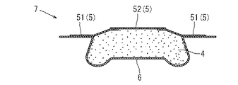
本実施の形態においては、シートカバー6とシートパッド4と裏面材5が一体成形されているシートパッド構造体7を備える乗物用シート1であり、車両用シートである。シートパッド4の着座面側にシートカバー6が配置されており、裏面材5はシートカバー6と対になってシートパッド4を挟みこむように位置している。
本実施の形態においては、シートパッド4に対して裏面材5が二つ備えられており、第1の裏面材51は中央に開口部を設けている裏面材5であり、第2の裏面材52は、第1の裏面材51に設けられた開口部を塞ぐように配置されている。
本実施の形態においては、発泡原液9として使用されるウレタン原液91を化学反応させることで発泡し、シートパッド4を成形している。
Hereinafter, embodiments for carrying out the present invention will be described with reference to the drawings as appropriate. In addition, the figure shown in order to demonstrate the manufacturing method of a molded object is taken as the figure which picked up the characteristic part exaggeratedly in order to use for an understanding of invention. Therefore, the shape of the
In the present embodiment, the
In the present embodiment, two
In the present embodiment, the
次に、シートパッド4を成形するために使用する成形型10について簡単に説明する。
成形型10は、複数の分割体を重ね合わせることで中央部分を中空状に構成するものであり、発泡成形するために使用される発泡型である。
ここでは、成形型10の分割体として、下型102、中型103、上型101を備えた成形型10である(図3、図4参照)。なお、下型102、中型103、上型101は、それぞれが図示しないヒンジにより結合されている。
下型102は、シートカバー6をその内面に沿うように配置する金型であり、ウレタン原液91が投入される器状の金型である。
中型103は、下型102に配置したシートカバー6を下型102とともに挟み込むことで、固定する役割を担うものである。当該中型103は中央部分に開口部を備えており、枠だけが設けられたような構造である。当該開口部よりウレタン原液91が投入可能となっている。また、当該開口部は上型101により塞がれることになる部分でもある。
上型101は、中型103に設けられた開口部を塞ぐために使用される金型であり、シートパッド4の裏面側(シートカバー6が位置する側とは反対側)の形状を主として定める型である。
Next, the forming die 10 used for forming the
The molding die 10 is a foaming die used for foam molding by forming a central portion in a hollow shape by overlapping a plurality of divided bodies.
Here, the
The
The
The
次に、シートパッド構造体7を製造する方法について説明する。
図3に示すように、器状の下型102の内面に沿うようにシートカバー6をセットする。この際、シートカバー6の着座面が下型102の内面と対向するようにセットする。シートカバー6のセットは細心の注意が必要であるため、人手により下型102に密着させてセットされる。
シートカバー6を下型102にセットした後に、枠形状の下型102の縁に沿うように中型103を重ねる。中型103の下面には第1の裏面材51が仮留めされている。第1の裏面材51には図示しない磁石が備えられており、当該磁石がもたらす磁力により中型103と仮留めされている。第1の裏面材51の一部は、中型103に設けた開口部側に突出するように配置されている。
下型102の縁に沿うように中型103を重ねることにより、シートカバー6が下型102に対してしっかりと固定される(図4参照)。これにより、以後の作業中にシートカバー6がずれてしまうことを防ぐことが可能となる。
この状態において、2液混合したウレタン原液91をシートカバー6上に注入する。ウレタン原液91を注入する際には、作業者から隔離した状態で注入するため、実際は、作業者が押しボタンを押すことにより、成形型10が移動し、移動した先でウレタン原液91が注入される。
なお、下型102と中型103によりシートカバー6が固定されることにより、成形型10が移動した際においても、シートカバー6がずれることを抑制することが可能となっている。
適量のウレタン原液91をシートカバー6上に注入した後、上型101を閉める(図4参照)。上型101の下面には第2の裏面材52が仮留めされている。第2の裏面材52にも第1の裏面材51と同様、図示しない磁石が備えられており、当該磁石がもたらす磁力により上型101と仮留めされている。
上型101に仮留めされている第2の裏面材52は、上型101に形成された面からはみ出すことは無く、上型101の下面に沿って配置されている。
上型101を中型103に重ね合わせることにより、上型101に配置されている第2の裏面材52が中型103に配置されている第1の裏面材51と重なり合う。なお、この状態において第1の裏面材51と第2の裏面材52とが完全に密着状態となっている必要性は無い。
本実施の形態においては、上型101と中型103との間に形成されるパーティングラインPLは、主として第1の裏面材51により覆い隠されるようになる。また、第1の裏面材51の端部は第2の裏面材52と重なり合うため、第1の裏面材51と第2の裏面材52との間に隙間が生じることが無い。なお、第1の裏面材51と第2の裏面材52が重なり合っている部分の長さは一律1cm程度となるように設定している。
Next, a method for manufacturing the
As shown in FIG. 3, the
After setting the
By overlapping the
In this state, a
Note that the
After injecting an appropriate amount of the
The second
By overlaying the
In the present embodiment, the parting line PL formed between the
上型101により中型103の開口部が塞がれた状態でウレタン原液91が発泡するように加熱し、化学反応させる。ウレタン原液91を発泡させて膨張させることにより成形型10内にウレタンが充填され、固化される(図4参照)。
ウレタンを成形型10内に充填させた後、冷却し、上型101をはずす。その後、中型103を外し、更には、成形体であるシートパッド構造体7を成形型10から抜き出す(図5参照)。
上記した一連の工程により、裏面材5とシートカバー6とシートパッド4が一体化したシートパッド構造体7が出来上がる。
当該シートパッド構造体7を通常通り、シートフレーム8に組み付け、その他の部位を装着することで、乗物用シート1が完成する。
In a state where the opening of the
After filling the
Through the series of steps described above, a
The
本実施の形態における図2においては、第3の裏面材53と第2の裏面材52とは、重ね合わせていない。これは、裏面材5が連続していない剛性度の低い部分を設けることで、エアバッグモジュール11から袋体が飛び出す際に、シートパッド4が破断できるようにするためである。つまり、シートパッド4の裏側は全ての部分において、剛性が求められるわけでは無く、全ての部分において、シートフレーム8などと接触するわけではないため、むしろ、裏面材5が不要な場所も存在する。本発明の製造方法は、必要箇所にのみ適応させれば良く、シートパッド4と一体化する全ての裏面材5について連続的に配設することを目的としているわけではない。
In FIG. 2 in the present embodiment, the third
上記した乗物用シート1の製造方法であれば、上型101と中型103を重ねることで生じたパーティングラインPL全体を裏面材5により覆うようにしているため、上型101と中型103との間の隙間にウレタン樹脂が侵入することを抑制できる。
また、隣接する裏面材5,5同士をオーバーラップさせながら配置しているので、裏面材5が配置できない部分が生じることによる不具合を回避可能である。
また、パーティングラインPLを裏面材5で覆うように配置するため、ウレタン樹脂が分割体間の隙間に侵入することを抑制できる。
また、裏面材5,5同士はウレタン樹脂により接着されることにもなるため、裏面材5を別途接合する作業が不要である。
また、ウレタンが成形型10内に充填される際には、発泡したウレタンが下方から上方などに向けて膨張していくため、第1の裏面材51は第2の裏面材52に向けて押し付けられるように働きうる。また、第1の裏面材51及び第2の裏面材52はウレタン樹脂を含浸することが可能であるので、第1の裏面材51に含浸したウレタン樹脂が第1の裏面材51と第2の裏面材52を接着させる働きも担う。また、ウレタンが発泡する際に膨張しても、パーティングラインPLを覆うように位置する第1の裏面材51の存在により、パーティングラインPL内にウレタンが侵入することが抑制される。
また、分割体から突出した裏面材5を上から覆うように別の裏面材5を配置することから、分割体同士の隙間に裏面材5が侵入することを抑制することが容易である。
また、ウレタン樹脂が含浸可能な裏面材5を選定しているため、裏面材5同士が接着されやすく、更には、裏面材5を配置した部分の剛性を高めやすい。
In the above-described method for manufacturing the
Moreover, since it arrange | positions, making the
Moreover, since it arrange | positions so that the parting line PL may be covered with the
Moreover, since the
Further, when urethane is filled in the
Moreover, since another
Moreover, since the
以上、一つの実施形態について説明したが、本発明は、上記実施形態のほか、その他各種の形態で実施可能なものである。
例えば、成形型は3つの分割体で構成されていなければならないものではなく、2つ若しくは4つ以上の分割体で構成することも可能である。ただし、シートカバーをシートパッドと一体に成形する際には、3つ以上の分割体で構成されていることが望ましい。例えば、二つの分割体でシートカバーを固定し、当該固定状態を目視で確認した後に、残りの分割体を組立てることが可能となるため、不良製品の発生を抑制することが可能となるからである。
また、成形型のパーティングライン全てを裏面材で覆うようにする必要性は無く、裏面材が配置できないことにより不具合が発生する部分においてのみ、本発明を実施すればよい。
また、シートパッドは、ウレタン原液を発泡して成形する必要性は無く、その他の公知の樹脂を採用することが可能である。
また、シートパッド構造体はシートカバーとシートパッドが一体成形されている必要は無く、シートパッドと裏面材が一体成形されたシートパッド構造体に対して後からシートカバーを被せて、乗物用シートに適用させるような構成としても良い。
また、裏面材は必ずしも発泡樹脂が含浸可能なものとする必要性は無く、複数の裏面材の全てを、同じ種類の裏面材とする必要性も無く、どのような形状であっても良い。
また、2枚の裏面材のみが重なる状態とする必要性は無く、3枚以上の裏面材が互いに重なり合うようにすることも可能である。
また、裏面材は上下方向に重ね合わせるものである必要性は無く、左右方向などに重ね合わせるものとすることも可能である。
また、裏面材は磁石を用いて分割体に仮留めしておく必要性は無く、分割体に係止部を設け、当該係止部に対して裏面材を仮留めするようにすることも可能である。
また、本実施の形態においては、裏面材はシートバックに設けているが、シートクッションに設けても良く、配置箇所にも限定は無い。
また、実施の形態においては第1の裏面材と第2の裏面材とが重なり合っている部分の長さは一律1cm程度となるように設定しているが、当該長さはそれより長くてもよいし、短くても良い。また、重なり合う長さを部分的に長くすることも短くすることも可能である。
また、乗物としては、車両であることに限らず、飛行機やヘリコプターなど空中を飛行する乗物や、船舶や潜水艇など海面や海中などを移動する乗物としてもよい。
Although one embodiment has been described above, the present invention can be implemented in various other forms besides the above embodiment.
For example, the mold does not have to be composed of three divided bodies, and can be composed of two or four or more divided bodies. However, when the seat cover is molded integrally with the seat pad, it is desirable that the seat cover is composed of three or more divided bodies. For example, it is possible to assemble the remaining divided bodies after fixing the seat cover with two divided bodies and visually confirming the fixed state, thereby suppressing the occurrence of defective products. is there.
Moreover, it is not necessary to cover the parting line of the molding die with the back surface material, and the present invention may be carried out only in a portion where a problem occurs because the back surface material cannot be arranged.
The seat pad is not required to be molded by foaming a urethane stock solution, and other known resins can be used.
In addition, the seat pad structure does not have to be integrally formed with the seat cover and the seat pad. The seat pad is covered with the seat pad structure on which the seat pad and the back surface material are integrally formed, and the vehicle seat. It is good also as a structure applied to.
Further, the back material is not necessarily required to be impregnated with foamed resin, and it is not necessary that all of the plurality of back materials be the same type of back material, and any shape may be used.
In addition, it is not necessary that only the two back materials overlap each other, and three or more back materials can overlap each other.
Further, the back material need not be superposed in the vertical direction, and can be superposed in the horizontal direction.
Also, there is no need to temporarily fasten the back material to the divided body using a magnet, and it is possible to provide a latching portion on the split body and temporarily fasten the back material to the latching portion. It is.
Moreover, in this Embodiment, although the back surface material is provided in the seat back, you may provide in a seat cushion and there is no limitation also in an arrangement | positioning location.
Moreover, in the embodiment, the length of the portion where the first back surface material and the second back surface material overlap is set to be about 1 cm uniformly, but the length may be longer than that. Good or short. In addition, the overlapping length can be partially increased or decreased.
The vehicle is not limited to a vehicle, and may be a vehicle that flies in the air such as an airplane or a helicopter, or a vehicle that moves on the sea surface or in the sea such as a ship or a submersible.
1 乗物用シート
2 シートバック
3 シートクッション
4 シートパッド
5 裏面材
6 シートカバー
7 シートパッド構造体
8 シートフレーム
9 発泡原液
10 成形型
11 エアバッグモジュール
51 第1の裏面材
52 第2の裏面材
53 第3の裏面材
101 上型
102 下型
103 中型
PL パーティングライン
DESCRIPTION OF
Claims (3)
前記シートパッドと前記裏面材とは、複数の分割体で構成される成形型において一体成形されており、
前記分割体同士を重ねあわせることにより形成されるパーティングラインの少なくとも一部を跨ぐように裏面材が配置された状態で、前記シートパッドと前記裏面材とが一体成形されることを特徴とする乗物用シートの製造方法。 A method of manufacturing a vehicle seat having a seat pad structure including a seat pad and a back material,
The seat pad and the back material are integrally formed in a molding die composed of a plurality of divided bodies,
The seat pad and the back material are integrally formed in a state where the back material is disposed so as to straddle at least a part of a parting line formed by overlapping the divided bodies. A method for manufacturing a vehicle seat.
複数の分割体が組み合わされることで構成される成形型の第1の分割体に対して第1の裏面材を配置し、
前記成形型の第2の分割体に対して第2の裏面材を配置し、
前記第1の分割体と前記第2の分割体を組み合わせることで、前記第1の裏面材の一部と前記第2の裏面材の一部が互いに重なるように隣接配置され、
前記第1の裏面材の一部と前記第2の裏面材の一部が互いに隣接配置された状態で成形することにより、シートパッドと裏面材が一体化されていることを特徴とする乗物用シートの製造方法。 A vehicle seat manufacturing method according to claim 1,
The first back material is arranged with respect to the first divided body of the molding die configured by combining a plurality of divided bodies,
Disposing a second back surface material on the second divided body of the mold,
By combining the first divided body and the second divided body, a part of the first back surface material and a part of the second back surface material are arranged adjacent to each other,
The vehicle is characterized in that the seat pad and the back material are integrated by molding in a state where a part of the first back material and a part of the second back material are arranged adjacent to each other. Sheet manufacturing method.
前記第1の分割体に対して第1の裏面材の一部が突出するように配置し、
前記第2の分割体を組み合わせた際に前記第2の裏面材の一部が前記第1の分割体から突出した前記第1の裏面材の一部と重なるように隣接配置された後に、成形型内の樹脂を膨張させて成形することにより、シートパッドと裏面材が一体化されることを特徴とする乗物用シートの製造方法。
A vehicle seat manufacturing method according to claim 2,
Arranged so that a part of the first back material protrudes with respect to the first divided body,
After the second divided body is combined, a part of the second back surface material is adjacently disposed so as to overlap with a part of the first back surface material protruding from the first divided body, and then molded. A method for manufacturing a vehicle seat, wherein a seat pad and a back material are integrated by expanding and molding a resin in a mold.
Priority Applications (3)
| Application Number | Priority Date | Filing Date | Title |
|---|---|---|---|
| JP2013070919A JP6221302B2 (en) | 2013-03-29 | 2013-03-29 | Vehicle seat manufacturing method |
| US14/227,288 US10611065B2 (en) | 2013-03-29 | 2014-03-27 | Manufacturing method for conveyance seat |
| CN201410126481.0A CN104070629B (en) | 2013-03-29 | 2014-03-31 | The manufacture method of seat for vehicle |
Applications Claiming Priority (1)
| Application Number | Priority Date | Filing Date | Title |
|---|---|---|---|
| JP2013070919A JP6221302B2 (en) | 2013-03-29 | 2013-03-29 | Vehicle seat manufacturing method |
Publications (2)
| Publication Number | Publication Date |
|---|---|
| JP2014193231A true JP2014193231A (en) | 2014-10-09 |
| JP6221302B2 JP6221302B2 (en) | 2017-11-01 |
Family
ID=51592441
Family Applications (1)
| Application Number | Title | Priority Date | Filing Date |
|---|---|---|---|
| JP2013070919A Active JP6221302B2 (en) | 2013-03-29 | 2013-03-29 | Vehicle seat manufacturing method |
Country Status (3)
| Country | Link |
|---|---|
| US (1) | US10611065B2 (en) |
| JP (1) | JP6221302B2 (en) |
| CN (1) | CN104070629B (en) |
Cited By (1)
| Publication number | Priority date | Publication date | Assignee | Title |
|---|---|---|---|---|
| CN108327588A (en) * | 2017-01-20 | 2018-07-27 | 福特全球技术公司 | Fixing device for fixing seat cover |
Families Citing this family (5)
| Publication number | Priority date | Publication date | Assignee | Title |
|---|---|---|---|---|
| DE102016109924A1 (en) * | 2016-05-30 | 2017-11-30 | Ford-Werke Gmbh | Seat back trim and method of making same |
| CN106393544B (en) * | 2016-11-30 | 2019-10-11 | 延锋安道拓座椅有限公司 | It is a kind of without sewing integral type surface cover foaming structure and to prepare mold and preparation method |
| CN111168913B (en) * | 2019-09-02 | 2022-06-17 | 天津三和泰奥汽车部件有限公司 | 3D (three-dimensional) setting device and production method for non-woven fabric for foaming of automobile seat |
| US20220227273A1 (en) * | 2021-01-20 | 2022-07-21 | Faurecia Automotive Seating, Llc | Vehicle seat panel with discontinuous foam layer |
| WO2023218722A1 (en) * | 2022-05-11 | 2023-11-16 | 株式会社型技術事務所モート | Method and apparatus for producing seat pad reinforcing cloth, and molding die |
Citations (5)
| Publication number | Priority date | Publication date | Assignee | Title |
|---|---|---|---|---|
| JPH0238008A (en) * | 1988-07-28 | 1990-02-07 | Ikeda Bussan Co Ltd | Integral mold of skin material and pad material |
| JPH0263805A (en) * | 1988-08-31 | 1990-03-05 | Ikeda Bussan Co Ltd | Monolithic foam molding method of skin material and pad material |
| JPH06206229A (en) * | 1993-01-11 | 1994-07-26 | Kansei Corp | Foamed molded product and molding thereof |
| FR2883790A1 (en) * | 2005-04-05 | 2006-10-06 | Faurecia Sieges Automobile | Manufacturing process for padded article such as vehicle seat component uses rigid backing panel with turned-over edges to press in lips of supple covering material |
| JP2012034894A (en) * | 2010-08-09 | 2012-02-23 | Inoac Corp | Back surface material and method of manufacturing seat cushion |
Family Cites Families (16)
| Publication number | Priority date | Publication date | Assignee | Title |
|---|---|---|---|---|
| GB1466531A (en) * | 1974-01-15 | 1977-03-09 | Sanson Joseph | Manufacture of cushions |
| AU592592B2 (en) * | 1986-09-15 | 1990-01-18 | Tachi-S Co., Ltd. | Vehicle seat |
| DE3823584A1 (en) * | 1988-07-12 | 1990-01-18 | Grammer Sitzsysteme Gmbh | METHOD FOR PRODUCING A UPHOLSTERY PART |
| US5096639A (en) * | 1990-03-28 | 1992-03-17 | Woodbridge Foam Corporation | Process for manufacturing a padded element |
| AU5623800A (en) | 1999-06-18 | 2001-01-09 | Magna Seating Systems Inc. | Method of making a foam pad having a sensor mat embedded therein |
| US6685862B1 (en) * | 2002-08-28 | 2004-02-03 | Corbin Pacific, Inc. | Method of making a vehicle seat |
| US7201112B2 (en) * | 2003-02-18 | 2007-04-10 | Jolley Mark W | Filled shell devices and methods of manufacturing |
| JP2005237491A (en) | 2004-02-24 | 2005-09-08 | Toyo Tire & Rubber Co Ltd | Seat pad and manufacturing method thereof |
| US7444700B2 (en) * | 2004-10-21 | 2008-11-04 | Sears Manufacturing Co. | Seat cushion with integral cover attachment |
| JP5189486B2 (en) | 2006-03-31 | 2013-04-24 | テイ・エス テック株式会社 | Cushion body, seat and method for manufacturing the same |
| JP4716521B2 (en) | 2007-06-15 | 2011-07-06 | 東海興業株式会社 | Cushion body manufacturing method |
| BRPI0923270B1 (en) | 2008-12-03 | 2019-10-01 | Nissan Motor Co., Ltd. | APPLIANCE FOR PRODUCING A FOAM MOLDING ELEMENT, METHOD FOR PRODUCING A FOAM MOLDING ELEMENT, FOAM MOLDING ELEMENT |
| JP2011110798A (en) | 2009-11-26 | 2011-06-09 | Bridgestone Corp | Support material, foam molding member and foam molding method |
| JP6173657B2 (en) * | 2011-07-14 | 2017-08-02 | キョーラク株式会社 | Molding method of resin molded products |
| JP5936848B2 (en) * | 2011-11-18 | 2016-06-22 | トヨタ紡織株式会社 | Vehicle seat and manufacturing method thereof |
| JP6015492B2 (en) * | 2013-02-27 | 2016-10-26 | トヨタ紡織株式会社 | Sheet component and manufacturing method thereof |
-
2013
- 2013-03-29 JP JP2013070919A patent/JP6221302B2/en active Active
-
2014
- 2014-03-27 US US14/227,288 patent/US10611065B2/en active Active
- 2014-03-31 CN CN201410126481.0A patent/CN104070629B/en active Active
Patent Citations (5)
| Publication number | Priority date | Publication date | Assignee | Title |
|---|---|---|---|---|
| JPH0238008A (en) * | 1988-07-28 | 1990-02-07 | Ikeda Bussan Co Ltd | Integral mold of skin material and pad material |
| JPH0263805A (en) * | 1988-08-31 | 1990-03-05 | Ikeda Bussan Co Ltd | Monolithic foam molding method of skin material and pad material |
| JPH06206229A (en) * | 1993-01-11 | 1994-07-26 | Kansei Corp | Foamed molded product and molding thereof |
| FR2883790A1 (en) * | 2005-04-05 | 2006-10-06 | Faurecia Sieges Automobile | Manufacturing process for padded article such as vehicle seat component uses rigid backing panel with turned-over edges to press in lips of supple covering material |
| JP2012034894A (en) * | 2010-08-09 | 2012-02-23 | Inoac Corp | Back surface material and method of manufacturing seat cushion |
Cited By (1)
| Publication number | Priority date | Publication date | Assignee | Title |
|---|---|---|---|---|
| CN108327588A (en) * | 2017-01-20 | 2018-07-27 | 福特全球技术公司 | Fixing device for fixing seat cover |
Also Published As
| Publication number | Publication date |
|---|---|
| CN104070629B (en) | 2017-10-24 |
| US10611065B2 (en) | 2020-04-07 |
| CN104070629A (en) | 2014-10-01 |
| JP6221302B2 (en) | 2017-11-01 |
| US20140291880A1 (en) | 2014-10-02 |
Similar Documents
| Publication | Publication Date | Title |
|---|---|---|
| JP6221302B2 (en) | Vehicle seat manufacturing method | |
| CN104582538B (en) | Seat cushion | |
| JP6094323B2 (en) | Vehicle seat | |
| US10710471B2 (en) | Method and foam die for manufacturing seat cushion material | |
| JP5905288B2 (en) | Manufacturing method of mold and foam molding | |
| CN104643684B (en) | Seat cushion and its manufacture method | |
| JP2015223921A (en) | Vehicular seat | |
| JP5901334B2 (en) | Mold and method for producing foamed molded body | |
| CN104708750A (en) | Method of manufacture of seat pad | |
| JP5444520B1 (en) | Vehicle interior board and manufacturing method thereof | |
| CA2868301A1 (en) | Foamed synthetic resin molded body and method for producing same | |
| JP2015103365A (en) | Battery container | |
| CN203844640U (en) | Vehicle seat | |
| CN102971125B (en) | Method for producing molded foam product, equipment for producing molded foam product, and molded foam product | |
| JP5940499B2 (en) | Method for producing foam molded member and impact absorbing member | |
| JPS6327211A (en) | Molding method of foam provided with skin material unitarily | |
| JP7480148B2 (en) | Sound insulation element for the front wall of a vehicle body and a support element for such a sound insulation element | |
| KR20190124221A (en) | Car Seat Cushion Core | |
| JP2013233680A (en) | Mold and method of producing foamed molded body | |
| US20180290352A1 (en) | Method for manufacturing seat cushion material | |
| JP7095153B2 (en) | How to make a ducted seat pad | |
| JP2018011647A (en) | Method for manufacturing vehicle seat pad | |
| JP2000233415A (en) | Molding method of integral foam molding |
Legal Events
| Date | Code | Title | Description |
|---|---|---|---|
| A621 | Written request for application examination |
Free format text: JAPANESE INTERMEDIATE CODE: A621 Effective date: 20150824 |
|
| A977 | Report on retrieval |
Free format text: JAPANESE INTERMEDIATE CODE: A971007 Effective date: 20160628 |
|
| A131 | Notification of reasons for refusal |
Free format text: JAPANESE INTERMEDIATE CODE: A131 Effective date: 20160705 |
|
| A521 | Request for written amendment filed |
Free format text: JAPANESE INTERMEDIATE CODE: A523 Effective date: 20160822 |
|
| A131 | Notification of reasons for refusal |
Free format text: JAPANESE INTERMEDIATE CODE: A131 Effective date: 20170117 |
|
| A521 | Request for written amendment filed |
Free format text: JAPANESE INTERMEDIATE CODE: A523 Effective date: 20170309 |
|
| A131 | Notification of reasons for refusal |
Free format text: JAPANESE INTERMEDIATE CODE: A131 Effective date: 20170815 |
|
| A521 | Request for written amendment filed |
Free format text: JAPANESE INTERMEDIATE CODE: A523 Effective date: 20170822 |
|
| TRDD | Decision of grant or rejection written | ||
| A01 | Written decision to grant a patent or to grant a registration (utility model) |
Free format text: JAPANESE INTERMEDIATE CODE: A01 Effective date: 20170905 |
|
| A61 | First payment of annual fees (during grant procedure) |
Free format text: JAPANESE INTERMEDIATE CODE: A61 Effective date: 20170918 |
|
| R151 | Written notification of patent or utility model registration |
Ref document number: 6221302 Country of ref document: JP Free format text: JAPANESE INTERMEDIATE CODE: R151 |
|
| R250 | Receipt of annual fees |
Free format text: JAPANESE INTERMEDIATE CODE: R250 |
|
| R250 | Receipt of annual fees |
Free format text: JAPANESE INTERMEDIATE CODE: R250 |
|
| R250 | Receipt of annual fees |
Free format text: JAPANESE INTERMEDIATE CODE: R250 |
|
| R250 | Receipt of annual fees |
Free format text: JAPANESE INTERMEDIATE CODE: R250 |
|
| R250 | Receipt of annual fees |
Free format text: JAPANESE INTERMEDIATE CODE: R250 |
|
| R250 | Receipt of annual fees |
Free format text: JAPANESE INTERMEDIATE CODE: R250 |