JP2014196631A - Spandrel wall panel frame fixing structure - Google Patents
Spandrel wall panel frame fixing structure Download PDFInfo
- Publication number
- JP2014196631A JP2014196631A JP2013073112A JP2013073112A JP2014196631A JP 2014196631 A JP2014196631 A JP 2014196631A JP 2013073112 A JP2013073112 A JP 2013073112A JP 2013073112 A JP2013073112 A JP 2013073112A JP 2014196631 A JP2014196631 A JP 2014196631A
- Authority
- JP
- Japan
- Prior art keywords
- waist wall
- wall panel
- panel frame
- frame fixing
- fixing structure
- Prior art date
- Legal status (The legal status is an assumption and is not a legal conclusion. Google has not performed a legal analysis and makes no representation as to the accuracy of the status listed.)
- Granted
Links
Images





Landscapes
- Steps, Ramps, And Handrails (AREA)
Abstract
Description
この発明は、バルコニーの腰壁パネルフレーム固定構造に関する。 The present invention relates to a structure for fixing a waist wall panel frame of a balcony.
特許文献1には、バルコニーの外部床の本体部の外側を外部カバーで覆い、その外部カバーと本体部との間の空間を防水カバーで上方から覆うとともに、この防水カバーを貫通して手摺り支柱を上方へ立ち上がらせたものにおいて、水密材を裏張りした防水キャップを、前記手摺り支柱へ外嵌するようにして前記防水カバーの上面を被覆してなるバルコニーの外部床における手摺り支柱根元部の防水構造が開示されている。
In
また、他の従来のバルコニー構造として、図8に示すように、バルコニー梁101のフランジ上に支柱102を接合する場合にボルト103とナット104とを用いる構造がある。しかしながら、この構造では、上記フランジ上から突出する上記ボルト103の頭部(図の点線丸囲み参照)がバルコニー床の防水施工材と干渉することがある。一方、図示はしていなが、バルコニー梁の外側に取合いプレートを設けて支柱金物を取り付ける構造の場合、腰壁設置前に上記支柱金物を本締めする必要がある。このため、両側2本の支柱金物の間に腰壁パネルを円滑に施工するためには、上記腰壁パネルをマイナス公差で作製するか、バルコニー梁のウェブに手が入る貫通穴を開けて内側から施工できるようにする必要がある。
As another conventional balcony structure, as shown in FIG. 8, there is a structure in which a
また、図9に示すように、腰壁パネル105の上下位置で左右の腰壁を固定する場合、支柱102を腰壁と同じ高さにするための加工精度が必要になると同時に支柱が長くなり、コスト高になる。一方、腰壁パネル105の上下の中間位置において支柱102と上記腰壁パネル105とを固定する場合、腰壁パネルに外装材105aが貼られていると、支柱102とボルト取り合いができる箇所が限られてくる。また、支柱102の配置間隔が大きくなると、パネルフレーム105の断面サイズをアップして自重に十分耐えるようにする必要がある。
In addition, as shown in FIG. 9, when the left and right waist walls are fixed at the upper and lower positions of the
上記特許文献1に開示の技術は、手摺り支柱が構成要素とされる構造であり、支柱を構成要素とすることにより生じる上記のような問題の解決は容易でない。
The technology disclosed in
この発明は、上記の事情に鑑み、支柱のない簡素化された構造で防水性および施工性を向上できる腰壁パネルフレーム固定構造を提供することを課題とする。 This invention makes it a subject to provide the waist wall panel frame fixing structure which can improve waterproofness and workability with the simplified structure without a support | pillar in view of said situation.
この発明の腰壁パネルフレーム固定構造は、上記の課題を解決するために、腰壁パネルフレームと、接合用板材に縦配置で腰壁取合いプレートが固定された腰壁パネルフレーム固定部材と、バルコニー梁の外側で上フランジと下フランジの両方に接合された梁取合い部材と、を備え、上記腰壁パネルフレーム固定部材における上記接合用板材が上記梁取合い部材に接合されており、上記腰壁取合いプレートを挟むように配置された隣り合う腰壁パネルフレームがその下部側で上記腰壁取合いプレートに固定されていることを特徴とする。 In order to solve the above problems, a waist wall panel frame fixing structure according to the present invention includes a waist wall panel frame, a waist wall panel frame fixing member in which a waist wall connection plate is fixed in a vertical arrangement on a joining plate, and a balcony. A beam joining member joined to both the upper flange and the lower flange on the outside of the beam, and the joining plate material in the waist wall panel frame fixing member is joined to the beam joining member, and the waist wall joining Adjacent waist wall panel frames arranged so as to sandwich the plate are fixed to the waist wall joint plate on the lower side thereof.
上記の構成であれば、上記バルコニー梁の上フランジと下フランジの両方に接合された梁取合い部材に上記腰壁パネルフレーム固定部材が固定されており、上記腰壁取合いプレートを挟むように配置された隣り合う腰壁パネルフレームがその下部側で上記腰壁取合いプレートに固定されるので、支柱のない構造のバルコニーが構築される。これにより、上記バルコニー梁の上フランジの上面を用いる支柱固定部とバルコニー床の防水施工材との干渉といった問題が無くなり、防水性を確保することが容易になる。また、支柱設置の作業が省略されるので、施工性も向上する。さらに、上記バルコニー梁の上フランジと下フランジの両方に接合された梁取合い部材に上記腰壁パネルフレーム固定部材が固定されるので、上記腰壁パネルフレームの取り付けの剛性が向上する。また、隣り合う腰壁パネルフレームの目地間を上記腰壁取合いプレートの厚みによって設定することができる。 In the above configuration, the waist wall panel frame fixing member is fixed to the beam joining member joined to both the upper flange and the lower flange of the balcony beam, and is arranged so as to sandwich the waist wall joining plate. Since the adjacent waist wall panel frames are fixed to the waist wall joining plate on the lower side, a balcony having a structure without a column is constructed. This eliminates the problem of interference between the column fixing portion using the upper surface of the upper flange of the balcony beam and the waterproof construction material of the balcony floor, and makes it easy to ensure waterproofness. Moreover, since the work of installing the support is omitted, workability is also improved. Further, since the waist wall panel frame fixing member is fixed to the beam connecting members joined to both the upper flange and the lower flange of the balcony beam, the rigidity of the attachment of the waist wall panel frame is improved. Further, the joint between adjacent waist wall panel frames can be set by the thickness of the waist wall connecting plate.
上記腰壁パネルフレームの下端には下向きに開口する切欠きが形成されており、上記腰壁取合いプレートの両面には上記隣り合う腰壁パネルフレームの上記切欠きに係合するピン部が設けられていてもよい。これによれば、上記腰壁パネルフレームの上記切欠きを上記ピン部に上から係合させるだけで当該ピン部を介して上記腰壁パネルフレームの重量が上記腰壁取合いプレートで受け止められることになる。また、上記腰壁パネルフレームに加わる水平力(風圧力)を、上記切欠きとピン部を介して上記腰壁取合いプレートが受け止めることになる。 A notch that opens downward is formed at the lower end of the waist wall panel frame, and pin portions that engage with the notches of the adjacent waist wall panel frames are provided on both sides of the waist wall coupling plate. It may be. According to this, the weight of the waist wall panel frame can be received by the waist wall connecting plate through the pin portion only by engaging the notch of the waist wall panel frame with the pin portion from above. Become. Further, the horizontal wall (wind pressure) applied to the waist wall panel frame is received by the waist wall connecting plate through the notch and the pin portion.
上記腰壁取合いプレートと上記腰壁パネルフレームとの固定のための締結部材が設けられる上記腰壁パネルフレームの箇所と、上記切欠きが形成される上記腰壁パネルフレームの箇所には、突出面部が形成されていてもよい。これによれば、上記バルコニー梁に先に取り付けられた上記腰壁パネルフレーム固定部材の位置に多少の誤差があっても、上記突出面部が小面積で上記腰壁取合いプレートに接触するため、摩擦が小さくなって上記腰壁パネルフレームを装着し易くなり、施工が容易になる。 Protruding surface portions are provided at a portion of the waist wall panel frame where a fastening member for fixing the waist wall connecting plate and the waist wall panel frame is provided, and at a portion of the waist wall panel frame where the notch is formed. May be formed. According to this, even if there is a slight error in the position of the waist wall panel frame fixing member attached to the balcony beam first, the protruding surface portion has a small area and comes into contact with the waist wall connecting plate. Becomes small and it becomes easy to mount the waist wall panel frame, and the construction becomes easy.
上記腰壁パネルフレームの上端には上向きに開口する切欠きが形成されており、上記隣り合う腰壁パネルフレームの上端部の間には、上記切欠きに係合するピン部を両面に有するスペーサーが設けられていてもよい。これによれば、隣り合う腰壁パネルフレームの上端部の目地間を上記スペーサーの厚みによって設定することができる。また、隣り合う腰壁パネルフレームの面ずれ(出入り)を上記ピン部と上記切欠きとの係合によって矯正することができる。 A notch that opens upward is formed at the upper end of the waist wall panel frame, and a spacer having pin portions that engage with the notch on both sides between the upper end portions of the adjacent waist wall panel frames. May be provided. According to this, the joint between the upper end portions of the adjacent waist wall panel frames can be set by the thickness of the spacer. Moreover, the surface shift | offset | difference (in / out) of an adjacent waist wall panel frame can be corrected by engagement with the said pin part and the said notch.
上記上向きに開口する切欠きが形成される上記腰壁パネルフレームの箇所には、突出面部が形成されていてもよい。これによれば、上記腰壁パネルフレームに接触する部材と当該腰壁パネルフレームとの適切な接触が上記突出面部によって容易に得られることになり、施工が容易になる。 A projecting surface portion may be formed at a portion of the waist wall panel frame where the notch opening upward is formed. According to this, appropriate contact between the member in contact with the waist wall panel frame and the waist wall panel frame can be easily obtained by the protruding surface portion, and the construction is facilitated.
上記腰壁パネルフレームには縦中桟が設けられており、この縦中桟の下部が上記バルコニー梁に支持されていてもよい。これによれば、上記縦中桟の箇所で上記腰壁パネルフレームの重量が上記バルコニー梁で受け止められる。 The waist wall panel frame may be provided with a vertical center beam, and a lower part of the vertical wall beam may be supported by the balcony beam. According to this, the weight of the said waist wall panel frame is received by the said balcony beam in the location of the said vertical middle crosspiece.
本発明であれば、支柱のない簡素化された構造で防水性および施工性を向上できるという効果を奏する。 If it is this invention, there exists an effect that waterproofness and workability can be improved with the simplified structure without a support | pillar.
以下、この発明の実施の形態を添付図面に基づいて説明する。
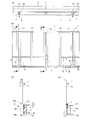
図1および図2に示すように、この実施形態の腰壁パネルフレーム固定構造は、腰壁パネルフレーム1と、接合用板材21の表面に縦配置で腰壁取合いプレート22が固定された腰壁パネルフレーム固定部材2と、H型鋼からなるバルコニー梁3に接合された梁取合い部材4とを備え、上記腰壁パネルフレーム固定部材2における上記接合用板材21の裏面が上記梁取合い部材4に接合されており、隣り合う腰壁パネルフレーム1がその縦フレーム11の下部側で上記腰壁取合いプレート22に固定されている。
Embodiments of the present invention will be described below with reference to the accompanying drawings.
As shown in FIG. 1 and FIG. 2, the waist wall panel frame fixing structure of this embodiment is a waist wall in which a waist
上記腰壁パネルフレーム1は、例えば、幅が2P(P=910mm)に設定されており、各サイドの縦フレーム11から1P(910mm)の箇所に縦中桟フレーム12が設けられており、0.5P(455mm)の箇所に桟木13が設けられている。
For example, the waist
上記梁取合い部材4は、上記バルコニー梁3の外側の上フランジ31と下フランジ32の両方に例えば溶接等によって接合されている。また、上記梁取合い部材4には2列で合計6個のボルト挿通孔が形成されている。そして、上記腰壁パネルフレーム固定部材2の接合用板材21にも2列で合計6個のボルト挿通孔が形成されており、上記ボルト挿通孔に通されたボルト51にナットを螺合させることで、上記腰壁パネルフレーム固定部材2がバルコニー梁3に固定されている。上記バルコニー梁3の外側縁から上記腰壁パネルフレーム1までの間隔は、この実施形態では10mmとなっており、この隙間に配置される上記接合用板材21の厚みが6mmに設定されていることから、上記ボルト51は皿頭ボルトとされ、頭部が接合用板材21の面から出ないようにしている。
The
上記腰壁パネルフレーム固定部材2における上記腰壁取合いプレート22の厚みは9mmとされている。また、上記腰壁取合いプレート22は上記梁取合い部材4の高さよりも高くされている。
The
図3にも示しているように、上記腰壁取合いプレート22の下部には、当該腰壁取合いプレート22の両面から突出するピン部22bが設けられている。そして、上記腰壁パネルフレーム1の縦フレーム11の下端には下向きに開口する切欠き11aが形成されている。上記隣り合う腰壁パネルフレーム1の上記切欠き11aに上記腰壁取合いプレート22のピン部22bが係合する。
As shown in FIG. 3,
また、上記腰壁取合いプレート22の上部にはボルト挿通孔22aが形成されている。このボルト挿通孔22aに挿通されたボルト52が上記隣り合う腰壁パネルフレーム1の縦フレーム11に形成されたボルト挿通孔にも通され、当該ボルト52の共縫い連結によって上記隣り合う腰壁パネルフレーム1が上記腰壁取合いプレート22に固定される。
A
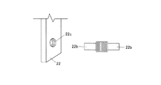
図4に示しているように、上記腰壁取合いプレート22には貫通螺子孔22cが形成されており、この貫通螺子孔22cに頭無しボルトが螺合される。この頭無しボルトにより、上記腰壁取合いプレート22の両面に突出する上記ピン部22bが形成される。もちろん、上記ピン部22bが上記頭無しボルトで作製されることに限られるものではない。
As shown in FIG. 4, the waist
上記隣り合う腰壁パネルフレーム1の上部側の間には、スペーサー6が設けられている。このスペーサー6の厚みは上記腰壁取合いプレート22と同じ9mm厚とされている。
A
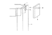
図5にも示しているように、上記スペーサー6には、当該スペーサー6の両面から突出するピン部61が設けられている。そして、上記腰壁パネルフレーム1の縦フレーム11の上端には上向きに開口する切欠き11bが形成されている。上記隣り合う腰壁パネルフレーム1の上記切欠き11bに上記スペーサー6のピン部61bが係合する。この係合は、上記腰壁パネルフレーム1を上記腰壁取合いプレート22に取り付けた後に行う。なお、上記スペーサー6には、上記腰壁取合いプレート22と同様に貫通螺子孔が形成されており、この貫通螺子孔に頭無しボルトが螺合されることにより、上記スペーサー6の両面から突出する上記ピン部61が形成される。
As shown in FIG. 5, the
上記腰壁パネルフレーム1における2本の縦中桟フレーム12の下部は上記バルコニー梁3に固定されている。具体的には、図6に示すように、梁取合い部材4Aは上記バルコニー梁3の上フランジ31と下フランジ32の両方に溶接等によって接合されている。上記梁取合い部材4Aには2箇所のボルト挿通孔が形成されている。そして、自重支持部材7には2列で合計4箇所のボルト挿通孔が形成されており、下側2個のボルト挿通孔と上記梁取合い部材4Aの2箇所のボルト挿通孔に挿通されたボルト(皿頭ボルト)によって、上記自重支持部材7が上記梁取合い部材4Aに固定される。そして、上記腰壁パネルフレーム1の縦中桟フレーム12に形成されたボルト挿通孔と上記自重支持部材7の上側2個のボルト挿通孔に挿通されたボルトによって上記縦中桟フレーム12が上記自重支持部材7に固定される。上記上側2個のボルト挿通孔が形成される部分は上記バルコニー梁3の上フランジ31よりも上に位置している。
The lower part of the two
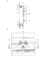
図7(A)にも示すように、上記腰壁取合いプレート22と上記腰壁パネルフレーム1との固定のための締結部材である上記ボルト52が設けられる上記縦フレーム11の箇所と、上記切欠き11aが形成される上記縦フレーム11の箇所には、突出面部11cが形成されている。また、図7(B)にも示すように、上記切欠き11bが形成される上記縦フレーム11の上端部の箇所にも、突出面部11cが形成されている。上記突出面部11cは例えばプレス加工によって形成することができる。
As shown in FIG. 7A, the
以上説明したように、上記バルコニー梁3の上フランジ31と下フランジ32の両方に接合された梁取合い部材4に上記腰壁パネルフレーム固定部材2が固定されており、上記腰壁取合いプレート22を挟むように配置された隣り合う腰壁パネルフレーム1がその下部側で上記腰壁取合いプレート2に固定されるので、支柱のない構造のバルコニーが構築される。これにより、上記バルコニー梁3の上フランジ31の上面を用いる支柱固定部とバルコニー床の防水施工材との干渉といった問題が無くなり、防水性を確保することが容易になる。また、支柱設置の作業が省略されるので、施工性も向上する。さらに、上記バルコニー梁3の上フランジ31と下フランジ32の両方に接合された梁取合い部材4に上記腰壁パネルフレーム固定部材2が固定されるので、上記腰壁パネルフレームの取り付けの剛性が向上する。また、隣り合う腰壁パネルフレーム1の目地間を上記腰壁取合いプレート22の厚みによって設定することができる。
As described above, the waist wall panel
上記腰壁パネルフレーム1の下端に下向きに開口する切欠き11aが形成されており、上記腰壁取合いプレート22の両面に上記隣り合う腰壁パネルフレーム1の切欠き11aに係合するピン部22bが設けられた構成であると、上記腰壁パネルフレーム1の上記切欠き11aを上記ピン部22bに上から係合させるだけで当該ピン部22bを介して上記腰壁パネルフレーム1の重量が上記腰壁取合いプレート22で受け止められることになる。また、上記腰壁パネルフレーム1に加わる水平力(風圧力)を、上記切欠き11aとピン部22bを介して上記腰壁取合いプレート22が受け止めることになる。ここで、上記腰壁パネルフレーム1の下端が上記バルコニー梁3の下に位置してボルト操作等が困難になるとしても、上記のように、上記腰壁パネルフレーム1の上記切欠き11aを上記ピン部22bに上から係合させる作業を行えばよいので何ら作業上の問題は生じない。
A
上記腰壁取合いプレート22と上記腰壁パネルフレーム1との固定のための締結部材である上記ボルト52が設けられる上記腰壁パネルフレーム1の箇所および上記切欠き11aが形成される上記腰壁パネルフレーム1の箇所に上記突出面部11cが形成されていると、上記バルコニー梁3に先に取り付けられた上記腰壁パネルフレーム固定部材2の位置に多少の誤差があっても、上記突出面部11cが小面積で上記腰壁取合いプレート22に接触するため、摩擦が小さくなって上記腰壁パネルフレーム1を装着し易くなり、施工が容易になる。
The location of the waist
上記腰壁パネルフレーム1の上端に上記上向きに開口する切欠き11bが形成されており、上記隣り合う腰壁パネルフレーム1の上端部の間に上記ピン部61を両面に有するスペーサー6が設けられていると、隣り合う腰壁パネルフレーム1の上端部の目地間を上記スペーサー6の厚みによって設定することができる。また、隣り合う腰壁パネルフレーム1の面ずれ(出入り)を上記ピン部61と上記切欠き11bとの係合によって矯正することができる。なお、上記隣り合う腰壁パネルフレーム1の上端部の間に頭つなぎ(隣り合う腰壁パネルフレーム1の上端部跨ぐ部材)を配置することで上記スペーサー6を省略することが可能である。一方、上記スペーサー6を設ける構成であれば、上記頭つなぎを配置しない構成とすることもでき、また、上記頭つなぎを配置するとしても、特に強度を持たせる必要がなくなり、美観や防水の観点から上記頭つなぎを選択することが可能になる。
A
上記切欠き11bが形成される上記腰壁パネルフレーム1の箇所に突出面部11cが形成されていると、上記腰壁パネルフレーム1に接触する部材(例えば、上記スペーサー6)と当該腰壁パネルフレーム1との平面接触が上記突出面部11cによって容易に得られることになり、施工が容易になる。
When the projecting
上記腰壁パネルフレーム1に縦中桟フレーム12が設けられており、この縦中桟フレーム12の下部が上記自重支持部材7を介して上記バルコニー梁3に支持されていると、上記縦中桟フレーム12の箇所で上記腰壁パネルフレーム1の重量が上記バルコニー梁3で受け止められることになる。ここで、上記腰壁パネルフレーム1の縦フレーム11や縦中桟フレーム12が風圧力に対して十分なフレーム断面を有する場合でも、タイル等が貼付されて腰壁パネルの自重が増加した場合やパネル幅が広くされる場合に、フレーム断面を大きくすることが望ましくなることがある。上記のように、上記縦中桟フレーム12の下部が上記自重支持部材7を介して上記バルコニー梁3に支持される構造であると、フレーム断面を大きくすることなく、上記タイル等が貼付されて腰壁パネルの自重が増加した場合やパネル幅を広くされる場合に対応することができる。なお、上記自重支持部材7については、腰壁パネルの自重を受ければよいので、上記腰壁取合いプレート22ほど長くない部材で足りる。
When the waist
以上、図面を参照してこの発明の実施形態を説明したが、この発明は、図示した実施形態のものに限定されない。図示した実施形態に対して、この発明と同一の範囲内において、あるいは均等の範囲内において、種々の修正や変形を加えることが可能である。 As mentioned above, although embodiment of this invention was described with reference to drawings, this invention is not limited to the thing of embodiment shown in figure. Various modifications and variations can be made to the illustrated embodiment within the same range or equivalent range as the present invention.
1 腰壁パネルフレーム
11 縦フレーム
11a 切欠き
11b 切欠き
11c 突出面部
2 腰壁パネルフレーム固定部材
21 接合用板材
22 腰壁取合いプレート
22a ボルト挿通孔
22b ピン部
3 バルコニー梁
31 上フランジ
32 下フランジ
4 梁取合い部材
52 ボルト(締結部材)
6 スペーサー
61 ピン部
7 自重支持部材
DESCRIPTION OF
6
Claims (6)
Priority Applications (1)
| Application Number | Priority Date | Filing Date | Title |
|---|---|---|---|
| JP2013073112A JP6174886B2 (en) | 2013-03-29 | 2013-03-29 | Lumbar panel frame fixing structure |
Applications Claiming Priority (1)
| Application Number | Priority Date | Filing Date | Title |
|---|---|---|---|
| JP2013073112A JP6174886B2 (en) | 2013-03-29 | 2013-03-29 | Lumbar panel frame fixing structure |
Publications (2)
| Publication Number | Publication Date |
|---|---|
| JP2014196631A true JP2014196631A (en) | 2014-10-16 |
| JP6174886B2 JP6174886B2 (en) | 2017-08-02 |
Family
ID=52357603
Family Applications (1)
| Application Number | Title | Priority Date | Filing Date |
|---|---|---|---|
| JP2013073112A Active JP6174886B2 (en) | 2013-03-29 | 2013-03-29 | Lumbar panel frame fixing structure |
Country Status (1)
| Country | Link |
|---|---|
| JP (1) | JP6174886B2 (en) |
Citations (5)
| Publication number | Priority date | Publication date | Assignee | Title |
|---|---|---|---|---|
| JPH0274405U (en) * | 1988-11-29 | 1990-06-07 | ||
| JPH034803U (en) * | 1989-06-01 | 1991-01-18 | ||
| JPH0354406U (en) * | 1989-09-25 | 1991-05-27 | ||
| JPH08218487A (en) * | 1995-02-10 | 1996-08-27 | Natl House Ind Co Ltd | Auxiliary structure |
| JP2012117322A (en) * | 2010-12-02 | 2012-06-21 | Asahi Kasei Homes Co | Spandrel wall structure and construction method therefor |
-
2013
- 2013-03-29 JP JP2013073112A patent/JP6174886B2/en active Active
Patent Citations (5)
| Publication number | Priority date | Publication date | Assignee | Title |
|---|---|---|---|---|
| JPH0274405U (en) * | 1988-11-29 | 1990-06-07 | ||
| JPH034803U (en) * | 1989-06-01 | 1991-01-18 | ||
| JPH0354406U (en) * | 1989-09-25 | 1991-05-27 | ||
| JPH08218487A (en) * | 1995-02-10 | 1996-08-27 | Natl House Ind Co Ltd | Auxiliary structure |
| JP2012117322A (en) * | 2010-12-02 | 2012-06-21 | Asahi Kasei Homes Co | Spandrel wall structure and construction method therefor |
Also Published As
| Publication number | Publication date |
|---|---|
| JP6174886B2 (en) | 2017-08-02 |
Similar Documents
| Publication | Publication Date | Title |
|---|---|---|
| KR101099368B1 (en) | Curtain wall | |
| JP6612552B2 (en) | Fireproof pillar and load bearing wall provided with the same | |
| JP6174886B2 (en) | Lumbar panel frame fixing structure | |
| KR200490405Y1 (en) | Bracket for switchgear | |
| US20070251409A1 (en) | Car wall arrangement for an elevator car | |
| JP6177759B2 (en) | Oversized exterior wall panel | |
| KR102009100B1 (en) | Control panel of elevator | |
| JP2018050661A (en) | Side frame structure of rack | |
| KR101106693B1 (en) | Leak-proof structure of metal panel roof | |
| KR20160043284A (en) | A transparent soundproof frame assembly | |
| JP5894562B2 (en) | Building corner structure | |
| JP5759317B2 (en) | Beam-column connection structure and member | |
| JP2019011647A (en) | Exterior wall panel, exterior wall structure, and exterior wall construction method | |
| JP5921954B2 (en) | Bearing wall | |
| JP5984664B2 (en) | Column connection structure | |
| JP7516304B2 (en) | wall | |
| JP7560339B2 (en) | wall | |
| JP7624826B2 (en) | wall | |
| JP2012241316A (en) | Corner eaves | |
| JP5708386B2 (en) | Partition panel | |
| KR20120061120A (en) | Structure for mounting of ceiling panel | |
| JP6717571B2 (en) | Waist wall panel fixing structure | |
| JP5898654B2 (en) | Lumbar panel frame fixing structure | |
| JP6170451B2 (en) | Side railing wall mounting structure of balcony | |
| JP4984826B2 (en) | Connecting bracket for building and connecting structure using the same |
Legal Events
| Date | Code | Title | Description |
|---|---|---|---|
| A621 | Written request for application examination |
Free format text: JAPANESE INTERMEDIATE CODE: A621 Effective date: 20160310 |
|
| A977 | Report on retrieval |
Free format text: JAPANESE INTERMEDIATE CODE: A971007 Effective date: 20161128 |
|
| A131 | Notification of reasons for refusal |
Free format text: JAPANESE INTERMEDIATE CODE: A131 Effective date: 20161206 |
|
| A521 | Request for written amendment filed |
Free format text: JAPANESE INTERMEDIATE CODE: A523 Effective date: 20170130 |
|
| TRDD | Decision of grant or rejection written | ||
| A01 | Written decision to grant a patent or to grant a registration (utility model) |
Free format text: JAPANESE INTERMEDIATE CODE: A01 Effective date: 20170613 |
|
| A61 | First payment of annual fees (during grant procedure) |
Free format text: JAPANESE INTERMEDIATE CODE: A61 Effective date: 20170707 |
|
| R150 | Certificate of patent or registration of utility model |
Ref document number: 6174886 Country of ref document: JP Free format text: JAPANESE INTERMEDIATE CODE: R150 |
|
| R250 | Receipt of annual fees |
Free format text: JAPANESE INTERMEDIATE CODE: R250 |
|
| R250 | Receipt of annual fees |
Free format text: JAPANESE INTERMEDIATE CODE: R250 |