JP2014200413A - Shoe - Google Patents
Shoe Download PDFInfo
- Publication number
- JP2014200413A JP2014200413A JP2013077879A JP2013077879A JP2014200413A JP 2014200413 A JP2014200413 A JP 2014200413A JP 2013077879 A JP2013077879 A JP 2013077879A JP 2013077879 A JP2013077879 A JP 2013077879A JP 2014200413 A JP2014200413 A JP 2014200413A
- Authority
- JP
- Japan
- Prior art keywords
- shoe
- pump
- air
- check valve
- outflow
- Prior art date
- Legal status (The legal status is an assumption and is not a legal conclusion. Google has not performed a legal analysis and makes no representation as to the accuracy of the status listed.)
- Pending
Links
Images





Landscapes
- Footwear And Its Accessory, Manufacturing Method And Apparatuses (AREA)
Abstract
【課題】靴内部の空気が、歩行に伴って、強制的に入れ換えられ、夏場に湿気がこもって足が蒸れることを防止することができる靴を提供する。【解決手段】靴本体3の内面4の後方底面部5に、外部19の空気を靴内部6へ流入させるための流入用ポンプ7と、靴内部6の空気を外部19へ流出させるための流出用ポンプを、備える。流入用ポンプ7及び流出用ポンプが膨縮自在の袋体9及び逆止弁を備える。歩行者のかかとの上下動により、流入用ポンプ7と流出用ポンプが袋体9への空気の吸入及び排出を行って靴内部6の空気を入れ換えるように構成する。【選択図】図1An object of the present invention is to provide a shoe in which the air inside the shoe is forcibly replaced as it walks, and moisture can be prevented from becoming damp in the summer. SOLUTION: An inflow pump 7 for allowing air from the outside 19 to flow into the shoe interior 6 and an outflow for allowing the air inside the shoe interior 6 to flow out to the exterior 19 are provided on the rear bottom surface 5 of the inner surface 4 of the shoe body 3. A pump is provided. The inflow pump 7 and the outflow pump are provided with a bag body 9 and a check valve that can be expanded and contracted. The inflow pump 7 and the outflow pump suck and discharge air into the bag body 9 by the vertical movement of the pedestrian's heel so that the air in the shoe interior 6 is replaced. [Selection] Figure 1
Description
本発明は、靴に関する。 The present invention relates to a shoe.
一般に、靴は、履いたり脱いだりする上端縁口部以外に孔は無い(例えば、特許文献1参照)。 In general, shoes have no holes other than the upper edge portion that is worn or removed (see, for example, Patent Document 1).
従って、靴を履いた状態では内部の通気性が悪く、夏場に湿気がこもって足が蒸れるという欠点があった。 Therefore, when the shoes are worn, the inside air permeability is poor, and there is a drawback that the feet are moistened with moisture in summer.
解決しようとする課題は、夏場に湿気がこもって足が蒸れる点である。 The problem to be solved is that the feet get muddy during summer.
そこで、本発明に係る靴は、靴本体の内面の後方底面部に、外部の空気を靴内部へ流入させるための流入用ポンプと、靴内部の空気を外部へ流出させるための流出用ポンプを、備え、上記流入用ポンプ及び流出用ポンプが膨縮自在の袋体及び逆止弁を備え、歩行者のかかとの上下動により、上記流入用ポンプと上記流出用ポンプが上記袋体への空気の吸入及び排出を行って上記靴内部の空気を入れ換えるように構成したものである。
また、上記流入用ポンプ及び流出用ポンプの各々が、かかとによって圧縮される際に上記袋体から空気を排出する排出用逆止弁と、かかとによる圧縮が解放又は軽減される際に上記袋体に空気を吸入する吸入用逆止弁を有するものである。
Therefore, the shoe according to the present invention has an inflow pump for inflowing external air into the shoe inside and an outflow pump for outflowing air inside the shoe to the outside on the rear bottom surface of the inner surface of the shoe body. The inflow pump and the outflow pump are provided with a bag body and a check valve that can be expanded and contracted, and the inflow pump and the outflow pump move air to the bag body by vertical movement of a pedestrian's heel. The shoes are inhaled and discharged to replace the air inside the shoe.
Further, when each of the inflow pump and the outflow pump is compressed by the heel, a discharge check valve for discharging air from the bag body, and the bag body when the compression by the heel is released or reduced. And an intake check valve for inhaling air.
また、上記靴本体の内面の底面部に中敷を有し、上記内面の底面部と上記中敷との間に、上記流入用ポンプ及び流出用ポンプを配設したものである。
また、上記流入用ポンプの上記吸入用逆止弁に吸気チューブが連通連結され、かつ、上記流出用ポンプの上記排出用逆止弁に排気チューブが連通連結され、上記吸気チューブ及び排気チューブは、靴本体の上端縁近傍に開口するように、靴本体に沿って設けられているものである。
The shoe body has an insole on the bottom surface of the inner surface, and the inflow pump and the outflow pump are disposed between the bottom surface of the inner surface and the insole.
In addition, an intake tube is connected in communication with the intake check valve of the inflow pump, and an exhaust tube is connected in communication with the discharge check valve of the outflow pump. It is provided along the shoe body so as to open near the upper edge of the shoe body.
本発明の靴によれば、靴内部の空気が、歩行に伴って、強制的に入れ換えられ、夏場に湿気がこもって足が蒸れることを防止することができる。 According to the shoe of the present invention, the air inside the shoe is forcibly replaced with walking, and it is possible to prevent the feet from becoming damp and damp in summer.
以下、図示の実施の形態に基づいて本発明について詳説する。
図1〜図5は、本発明の第1の実施の形態を示す。この靴は長靴1から成り、2種類のポンプ2を備える。すなわち、靴本体3の内面4の後方底面部5に、外部19の空気を靴内部6へ流入させるための流入用ポンプ7と、靴内部6の空気を外部19へ流出させるための流出用ポンプ8を、備える。
Hereinafter, the present invention will be described in detail based on the illustrated embodiment.
1 to 5 show a first embodiment of the present invention. This shoe comprises
ポンプ2(流入用ポンプ7及び流出用ポンプ8)が膨縮自在の袋体9及び逆止弁10を備え、歩行者のかかとA(図6・図8参照)の上下動により、流入用ポンプ7と流出用ポンプ8が袋体9への空気の吸入及び排出を行って靴内部6の空気を入れ換えるように構成される。袋体9は、自由状態では膨らんだ状態となるような復元力を有する。例えば、袋体9の内部に弾性部材(図示省略)を有する。
The pump 2 (the
具体的には、流入用ポンプ7及び流出用ポンプ8の各々が、かかとAによって圧縮される際に袋体9から空気を排出する排出用逆止弁11と、かかとAによる圧縮が解放又は軽減される際に袋体9に空気を吸入する吸入用逆止弁12を有する。
Specifically, when each of the
靴本体3の内面4の底面部13に通気性を有する中敷14を有し、底面部13と中敷14との間に、流入用ポンプ7及び流出用ポンプ8が配設される。
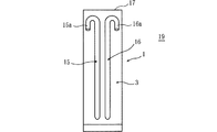
流入用ポンプ7の吸入用逆止弁12に吸気チューブ15が連通連結され、かつ、流出用ポンプ8の排出用逆止弁11に排気チューブ16が連通連結される。吸気チューブ15及び排気チューブ16は、靴本体3の上端縁17近傍に開口するように、靴本体3に沿って設けられている。吸気チューブ15の上開口部15a、及び、排気チューブ16の上開口部16aは、水平乃至下方へ折曲げられている。雨天時等に雨等が入るのを防止することができる。
流入用ポンプ7の排出用逆止弁11側には、足の甲部B(図6・図8参照)に空気を排出するための送風チューブ18が連通連結される。
An
An
On the
次に、歩行者のかかとAの上下動によって靴本体3の内部の空気を入れ換える作用について説明する。
歩行者のかかとAの上下動によって(歩行に伴って)、図6に示すようにかかとAがポンプ2を圧縮する状態と、図8に示すようにかかとAによるポンプ2の圧縮が解放又は軽減される状態を繰り返し、靴内部6の空気を入れ換える。
Next, the effect | action which replaces the air inside the shoe
As the pedestrian's heel A moves up and down (with walking), the heel A compresses the
図8の状態から図6の状態になると(すなわちかかとAがポンプ2を圧縮すると)、図7に示すように、ポンプ2の袋体9から空気が排出される。具体的には、流入用ポンプ7の袋体9から矢印Wに示すように排出用逆止弁11を通じて空気が靴内部6へ流入するとともに、流出用ポンプ8の袋体9から矢印Xに示すように排出用逆止弁11を通じて空気が外部19へ流出する。
When the state shown in FIG. 8 is changed to the state shown in FIG. 6 (that is, when the heel A compresses the pump 2), air is discharged from the
図6の状態から図8の状態になると(すなわちかかとAによる圧縮が解放又は軽減されると)、図9に示すように、ポンプ2の袋体9に空気が吸入される。具体的には、流入用ポンプ7の袋体9に矢印Yに示すように吸入用逆止弁12を通じて空気が外部19から袋体9へ吸入されるとともに、流出用ポンプ8の袋体9に矢印Zに示すように吸入用逆止弁12を通じて空気が靴内部6から袋体9へ吸入される。
When the state shown in FIG. 6 is changed to the state shown in FIG. 8 (that is, when compression by the heel A is released or alleviated), air is sucked into the
図10・図11は、第2の実施の形態を示す。吸気チューブ15の上開口部15a及び排気チューブ16の上開口部16aが折曲げられず上方へ開口している。吸気チューブ15の上開口部15a、及び、排気チューブ16の上開口部16aを、靴本体3の上端縁17近傍に取着した防水性垂れ片20にて被覆する。雨天時等に雨等が入るのを防止することができる。その他の構成は、第1の実施の形態と同様である。
10 and 11 show a second embodiment. The upper opening 15a of the
なお、図2に於て、逆止弁10を図示省略した。
本発明は、設計変更可能であって、例えば、ジョギングシューズから成るも良い。また、流入用ポンプ7と流出用ポンプ8を上下に配設したり、前後に配設するも良い。また、吸気チューブ15及び排気チューブ16を、靴本体3の内部に配設したり、内面4側に沿って配設するも良い。また、吸気チューブ15及び排気チューブ16を省略しても良い。
In FIG. 2, the
The present invention is changeable in design and may comprise, for example, a jogging shoe. Further, the
以上のように、本発明は、靴本体3の内面4の後方底面部5に、外部19の空気を靴内部6へ流入させるための流入用ポンプ7と、靴内部6の空気を外部19へ流出させるための流出用ポンプ8を、備え、流入用ポンプ7及び流出用ポンプ8が膨縮自在の袋体9及び逆止弁10を備え、歩行者のかかとAの上下動により、流入用ポンプ7と流出用ポンプ8が袋体9への空気の吸入及び排出を行って靴内部6の空気を入れ換えるように構成したので、靴内部6の空気が、歩行に伴って、強制的に入れ換えられ、夏場に湿気がこもって足が蒸れることを防止することができる。歩行者のかかとAの上下動を利用するので、省エネである。
As described above, according to the present invention, the
また、流入用ポンプ7及び流出用ポンプ8の各々が、かかとAによって圧縮される際に袋体9から空気を排出する排出用逆止弁11と、かかとAによる圧縮が解放又は軽減される際に袋体9に空気を吸入する吸入用逆止弁12を有するので、確実に空気の入れ換えを行うことができる。
Further, when each of the
また、靴本体3の内面4の底面部13に中敷14を有し、内面4の底面部13と中敷14との間に、流入用ポンプ7及び流出用ポンプ8を配設したので、履き心地が良い。
Further, since the
また、流入用ポンプ7の吸入用逆止弁12に吸気チューブ15が連通連結され、かつ、流出用ポンプ8の排出用逆止弁11に排気チューブ16が連通連結され、吸気チューブ15及び排気チューブ16は、靴本体3の上端縁17近傍に開口するように、靴本体3に沿って設けられているので、水たまりなどに入っても、水がポンプ2内に入ることを確実に防止することができる。
Further, an
3 靴本体
4 内面
5 後方底面部
6 靴内部
7 流入用ポンプ
8 流出用ポンプ
9 袋体
10 逆止弁
11 排出用逆止弁
12 吸入用逆止弁
13 底面部
14 中敷
15 吸気チューブ
16 排気チューブ
17 上端縁
19 外部
A かかと
DESCRIPTION OF
10 Check valve
11 Check valve for discharge
12 Check valve for suction
13 Bottom
14 Insole
15 Intake tube
16 Exhaust tube
17 Upper edge
19 External A heel
Claims (4)
Priority Applications (1)
| Application Number | Priority Date | Filing Date | Title |
|---|---|---|---|
| JP2013077879A JP2014200413A (en) | 2013-04-03 | 2013-04-03 | Shoe |
Applications Claiming Priority (1)
| Application Number | Priority Date | Filing Date | Title |
|---|---|---|---|
| JP2013077879A JP2014200413A (en) | 2013-04-03 | 2013-04-03 | Shoe |
Publications (1)
| Publication Number | Publication Date |
|---|---|
| JP2014200413A true JP2014200413A (en) | 2014-10-27 |
Family
ID=52351424
Family Applications (1)
| Application Number | Title | Priority Date | Filing Date |
|---|---|---|---|
| JP2013077879A Pending JP2014200413A (en) | 2013-04-03 | 2013-04-03 | Shoe |
Country Status (1)
| Country | Link |
|---|---|
| JP (1) | JP2014200413A (en) |
Cited By (2)
| Publication number | Priority date | Publication date | Assignee | Title |
|---|---|---|---|---|
| JP2020508707A (en) * | 2018-02-01 | 2020-03-26 | ナノテック セラミックス カンパニー リミテッドNanotech Ceramics Co., Ltd. | Prefabricated shoes with a double structure with improved ventilation |
| KR20210084774A (en) * | 2019-12-27 | 2021-07-08 | 주식회사 에스지 | Dehumidification device inside the fire helmet |
Citations (3)
| Publication number | Priority date | Publication date | Assignee | Title |
|---|---|---|---|---|
| JPS61163501U (en) * | 1985-03-31 | 1986-10-09 | ||
| JPH025901A (en) * | 1988-06-26 | 1990-01-10 | Hikojiro Taki | Shoe with ventilation device |
| JPH04240401A (en) * | 1991-01-22 | 1992-08-27 | Mikio Hayashi | Shoe |
-
2013
- 2013-04-03 JP JP2013077879A patent/JP2014200413A/en active Pending
Patent Citations (3)
| Publication number | Priority date | Publication date | Assignee | Title |
|---|---|---|---|---|
| JPS61163501U (en) * | 1985-03-31 | 1986-10-09 | ||
| JPH025901A (en) * | 1988-06-26 | 1990-01-10 | Hikojiro Taki | Shoe with ventilation device |
| JPH04240401A (en) * | 1991-01-22 | 1992-08-27 | Mikio Hayashi | Shoe |
Cited By (4)
| Publication number | Priority date | Publication date | Assignee | Title |
|---|---|---|---|---|
| JP2020508707A (en) * | 2018-02-01 | 2020-03-26 | ナノテック セラミックス カンパニー リミテッドNanotech Ceramics Co., Ltd. | Prefabricated shoes with a double structure with improved ventilation |
| JP7004705B2 (en) | 2018-02-01 | 2022-02-10 | ナノテック セラミックス カンパニー リミテッド | Double-structured prefabricated shoes with improved breathability |
| KR20210084774A (en) * | 2019-12-27 | 2021-07-08 | 주식회사 에스지 | Dehumidification device inside the fire helmet |
| KR102333605B1 (en) * | 2019-12-27 | 2021-12-03 | 주식회사 에스지 | Dehumidification device inside the fire helmet |
Similar Documents
| Publication | Publication Date | Title |
|---|---|---|
| CN105163618B (en) | A kind of ventilated footwear that pump action is played using outer bottom | |
| CN103734985B (en) | At the bottom of the interior circulation shoe of air-cushion type | |
| KR101188875B1 (en) | Balance functionality cushion shoes soles | |
| CN102292005B (en) | Ventilated shoes combined with impact absorption | |
| CN201150284Y (en) | Ventilation device for shoes and ventilation shoes | |
| KR101147675B1 (en) | The ventilation shoes with an abundant outside-air | |
| CN103462303B (en) | Ventilated footwear | |
| CN203952604U (en) | At the bottom of the interior circulation shoe of air-cushion type | |
| CN203735557U (en) | Breathable shoe with air circulation function | |
| KR200472230Y1 (en) | Air pump for footwear and footwear with the air pump | |
| CN201039786Y (en) | Respiration shoe pad | |
| KR100664396B1 (en) | Ventilation shoes with cushion function. | |
| CN206729323U (en) | A kind of breathable shoes | |
| JP2004290653A (en) | Push-pull air flow structure ventilation shoes | |
| JP2008161478A (en) | Insoles and shoes | |
| CN216853948U (en) | A kind of waterproof and antibacterial flip flops | |
| WO2016037593A1 (en) | Shoes ventilation system | |
| KR200479388Y1 (en) | Elasticity and well-ventilated shoes feature | |
| CN205214370U (en) | Air -permeable breathing shoes | |
| KR20130013052A (en) | Air circulation shoes insole | |
| CN213939884U (en) | Shock-absorbing buffering rubber sole | |
| JP3151107U (en) | Footwear prevention mechanism | |
| JP3837426B2 (en) | In-shoe ventilation device and ventilation shoes | |
| EP2334210B1 (en) | Device for internal ventilation of a shoe | |
| JP3117483U (en) | Insoles with shoes and air pump |
Legal Events
| Date | Code | Title | Description |
|---|---|---|---|
| A131 | Notification of reasons for refusal |
Free format text: JAPANESE INTERMEDIATE CODE: A131 Effective date: 20141125 |
|
| A521 | Request for written amendment filed |
Free format text: JAPANESE INTERMEDIATE CODE: A523 Effective date: 20141215 |
|
| A02 | Decision of refusal |
Free format text: JAPANESE INTERMEDIATE CODE: A02 Effective date: 20150407 |