JP2014200425A - Electric razor - Google Patents

Electric razor Download PDF

Info

Publication number
JP2014200425A
JP2014200425A JP2013078360A JP2013078360A JP2014200425A JP 2014200425 A JP2014200425 A JP 2014200425A JP 2013078360 A JP2013078360 A JP 2013078360A JP 2013078360 A JP2013078360 A JP 2013078360A JP 2014200425 A JP2014200425 A JP 2014200425A
Authority
JP
Japan
Prior art keywords
blade
disk
inner blade
small
razor
Prior art date
Legal status (The legal status is an assumption and is not a legal conclusion. Google has not performed a legal analysis and makes no representation as to the accuracy of the status listed.)
Granted
Application number
JP2013078360A
Other languages
Japanese (ja)
Other versions
JP6088891B2 (en
Inventor
岩倉 幸太郎
Kotaro Iwakura
幸太郎 岩倉
祐吾 渡利
Yugo Watari
祐吾 渡利
誠虎 東
Makoto Azuma
誠虎 東
Current Assignee (The listed assignees may be inaccurate. Google has not performed a legal analysis and makes no representation or warranty as to the accuracy of the list.)
Maxell Ltd
Original Assignee
Hitachi Maxell Ltd
Priority date (The priority date is an assumption and is not a legal conclusion. Google has not performed a legal analysis and makes no representation as to the accuracy of the date listed.)
Filing date
Publication date
Application filed by Hitachi Maxell Ltd filed Critical Hitachi Maxell Ltd
Priority to JP2013078360A priority Critical patent/JP6088891B2/en
Publication of JP2014200425A publication Critical patent/JP2014200425A/en
Application granted granted Critical
Publication of JP6088891B2 publication Critical patent/JP6088891B2/en
Active legal-status Critical Current
Anticipated expiration legal-status Critical

Links

Images

Landscapes

  • Dry Shavers And Clippers (AREA)

Abstract

【課題】シャープな切れ味を発揮しながら、小刃の構造強度を十分に確保することができ、しかも摺動抵抗が増大することの無い内刃を備える電気かみそりを提供する。
【解決手段】鋭角の切刃63を備える剪断面60の側縁を、平面視で凹縁部56と凸縁部57とが交互に連続する波形に形成する。側面62の下方部分に、剪断面60の側縁60aよりも側方側に突出する第1補強体65aを設ける。これにより、小刃51の構造強度の増加を図る。
【選択図】図1
Provided is an electric razor having an inner blade that can sufficiently ensure the structural strength of a small blade while exhibiting sharp sharpness and that does not increase sliding resistance.
A side edge of a shearing surface 60 having an acute cutting edge 63 is formed into a waveform in which concave edge portions 56 and convex edge portions 57 are alternately continuous in a plan view. A first reinforcing body 65 a that protrudes to the side of the side edge 60 a of the shear surface 60 is provided at a lower portion of the side surface 62. Thereby, the structural strength of the small blade 51 is increased.
[Selection] Figure 1

Description

本発明は電気かみそりに関する。   The present invention relates to an electric razor.

本出願人は、切断効率の向上を図ることを目的として、小刃の刃先を波状に屈曲させた電気かみそりの内刃を先に出願している(特許文献1)。この特許文献1においては、往復動するレシプロ刃の内刃において、展開した状態における小刃の平面視形状を、凹縁部と凸縁部とが交互に連続する屈曲形状に形成している。小刃は、上方の剪断面と下方の非剪断面と、これら両面の左右側縁間の肉壁を抉る左右の湾曲面とで、断面ベルマウス状に形成されており、小刃の剪断面の左右両側縁のそれぞれに、鋭角の切刃が形成されている。そして、凹縁部における湾曲面の抉り深さを、他より大きくして、凹縁部における切刃の角度を他の切刃部位より小さく設定することで、切断効率の向上を図っている。   For the purpose of improving cutting efficiency, the present applicant has applied for an inner blade of an electric razor in which the edge of a small blade is bent in a wave shape (Patent Document 1). In this Patent Document 1, in the inner blade of a reciprocating blade that reciprocates, the planar view shape of the small blade in the expanded state is formed into a bent shape in which concave edge portions and convex edge portions are alternately continued. The small blade has an upper shearing surface, a lower non-shearing surface, and left and right curved surfaces that sandwich the wall between the left and right side edges of each of these surfaces. A sharp cutting edge is formed on each of the left and right side edges. And the cutting depth of the curved surface in a concave edge part is made larger than others, and the cutting efficiency is aimed at by setting the angle of the cutting edge in a concave edge part smaller than other cutting blade site | parts.

また、本出願人は、所謂ロータリー式の電気かみそりの内刃構造の簡素化を図ることを目的として、軸本体と、軸本体の装着された複数のディスクと、ディスクの周囲に固定された切断刃とで構成された回転内刃を先に出願している(特許文献2)。この特許文献2においては、回転内刃を構成する全てのディスクは真円板状に形成されている。   In addition, the applicant of the present application aims to simplify the inner blade structure of a so-called rotary electric razor, a shaft body, a plurality of disks with the shaft body mounted thereon, and a cutting fixed around the disk. An application has been filed first for a rotating inner blade composed of a blade (Patent Document 2). In Patent Document 2, all the disks constituting the rotating inner blade are formed in a perfect disc shape.

特開2010−273809号公報JP 2010-273809 A 特開2012−183209号公報JP 2012-183209 A

上記の特許文献1における内刃の問題は、凹縁部を設けた分だけ小刃の断面面積が小さくなることが避けられず、小刃の構造強度が不足しやすいことにある。すなわち、縦断側面視における、剪断断面の左右側縁で規定される小刃の断面面積が、凹縁部を設けた分だけ小さくなり、構造強度が低下することが避けられない。かかる問題は、例えば剪断面の左右方向の長さ寸法を大きくすることで解決できるが、この場合には外刃に対する内刃の摺動抵抗が増加する。   The problem of the inner blade in Patent Document 1 is that the sectional area of the small blade is inevitably reduced by the amount of the concave edge portion, and the structural strength of the small blade tends to be insufficient. That is, it is inevitable that the cross-sectional area of the blade defined by the left and right edges of the sheared cross section in the longitudinal side view is reduced by the amount of the concave edge portion, and the structural strength is reduced. Such a problem can be solved, for example, by increasing the length of the shearing surface in the left-right direction. In this case, however, the sliding resistance of the inner blade relative to the outer blade increases.

また、本出願人は、ロータリー式の電気かみそりにおいて、内刃に対して肌面と直交する方向(縦方向)に振動を与えて、ひげを内刃内により深く進入させて、ひげを深剃りできることを考えた。しかしながら、特許文献2の形態において、内刃を縦方向に振動させようとすると、専用の振動機構が別途必要となるため、電気かみそりの製造コストが上昇することが避けられない。   In addition, in the rotary type electric shaver, the applicant applies a vibration in a direction (longitudinal direction) perpendicular to the skin surface with respect to the inner blade so that the beard enters deeper into the inner blade to shave the beard. I thought about what I could do. However, in the form of Patent Document 2, if the inner blade is caused to vibrate in the vertical direction, a dedicated vibration mechanism is required separately, and thus it is inevitable that the manufacturing cost of the electric razor increases.

本発明の目的は、シャープな切れ味を発揮しながら、小刃の構造強度を十分に確保することができ、しかも摺動抵抗が増大することの無い内刃を備える電気かみそりを提供することにある。
本発明の他の目的は、内刃が縦方向に振動する内刃振動機構を備える電気かみそりにおいて、専用の振動機構を必要とせず、製造コストの上昇を抑えることにある。
An object of the present invention is to provide an electric razor having an inner blade that can sufficiently ensure the structural strength of a small blade while exhibiting a sharp sharpness, and that does not increase sliding resistance. .
Another object of the present invention is to suppress an increase in manufacturing cost without requiring a dedicated vibration mechanism in an electric razor provided with an inner blade vibration mechanism in which the inner blade vibrates in the vertical direction.

本発明は、アーチ状に保形される外刃7と、外刃7の内面に摺接する内刃8とがかみそりヘッド2に設けられている電気かみそりを対象とする。内刃8は、リブ状の小刃51の一群と、小刃51で区画される刃穴53の一群とを備えている。小刃51は、外刃7の内面に接する剪断面60と、該剪断面60の反対面に位置する非剪断面61と、これら剪断面60と非剪断面61の側縁間を?ぐ側面62とで構成されている。そして、鋭角の切刃63を備える剪断面60の側縁が平面視で凹縁部56と凸縁部57とが交互に連続する波形に形成されており、側面62の下方部分に、剪断面60の側縁60aよりも側方側に突出する第1補強体65aが設けられていることを特徴とする。   The present invention is directed to an electric razor in which a razor head 2 is provided with an outer blade 7 that is shaped like an arch and an inner blade 8 that is in sliding contact with the inner surface of the outer blade 7. The inner blade 8 includes a group of rib-shaped small blades 51 and a group of blade holes 53 defined by the small blades 51. The small blade 51 includes a shearing surface 60 in contact with the inner surface of the outer blade 7, a non-shearing surface 61 located on the opposite surface of the shearing surface 60, and a side surface between the side edges of the shearing surface 60 and the non-shearing surface 61. 62. And the side edge of the shear surface 60 provided with the acute angle cutting edge 63 is formed in the waveform which the concave edge part 56 and the convex edge part 57 continue alternately by planar view, and the shear surface is formed in the lower part of the side surface 62. A first reinforcing body 65a that protrudes to the side of the side edge 60a of the 60 is provided.

本発明に係る電気かみそりは、ロータリー式の回転内刃を備えるロータリー式の電気かみそりのほか、往復動する内刃を備えるレシプロ式の電気かみそりやドーム状の回転内刃を備える電気かみそりなどにも適用することができる。   The electric razor according to the present invention is not only a rotary electric razor having a rotary rotating inner blade, but also a reciprocating electric razor having a reciprocating inner blade, an electric razor having a dome-shaped rotating inner blade, and the like. Can be applied.

隣り合う刃穴53の間には、複数本の小刃51が交差する交差部55が設けられており、交差部55の下方部分に、剪断面60の側縁60aよりも側方側に突出する第2補強体65bを設けることができる。   Between adjacent blade holes 53, a crossing portion 55 where a plurality of small blades 51 cross each other is provided, and protrudes laterally from the side edge 60a of the shear surface 60 at a lower portion of the crossing portion 55. A second reinforcing body 65b can be provided.

第1補強体65aと第2補強体65bとを連続させて、剪断面60から段落ちする段落ち空間66が連続されている形態を採ることができる。   The first reinforcing body 65a and the second reinforcing body 65b can be made continuous so that a step-down space 66 that steps down from the shear surface 60 is continuous.

第1補強体65aおよび/又は第2補強体65bの上部には、剪断面60から段落ちする段落ち空間66が形成されており、段落ち空間66に縦リブ67が部分的に形成されている形態を採ることができる。   In the upper part of the first reinforcing body 65a and / or the second reinforcing body 65b, a step-down space 66 that drops from the shear surface 60 is formed, and vertical ribs 67 are partially formed in the step-down space 66. Can take the form.

少なくとも第1補強体65aおよび/又は第2補強体65bの上部には、光触媒69を固定することができる。   The photocatalyst 69 can be fixed to at least the upper part of the first reinforcing body 65a and / or the second reinforcing body 65b.

また本発明に係る電気かみそりは、アーチ状に保形される外刃7と、外刃7の内面に摺接する内刃8とが、本体部1の上方に装着されたかみそりヘッド2に設けられている電気かみそりを対象とする。内刃8は、断面が円弧状に折り曲げられた切断刃32と、切断刃32を支持する回転軸体29とを備えており、回転軸体29は、軸本体30と、回転軸方向に並ぶ複数のディスク31とを備え、ディスク31の周面に切断刃32が固定されている。そして、回転軸体29を構成する一部又は全部のディスク31を、切欠き44を備える偏心ディスク31bとしたことを特徴とする。   In addition, the electric razor according to the present invention is provided in the razor head 2 in which an outer blade 7 that is shaped like an arch and an inner blade 8 that is in sliding contact with the inner surface of the outer blade 7 are mounted above the main body 1. The target is an electric razor. The inner blade 8 includes a cutting blade 32 whose section is bent in an arc shape, and a rotating shaft body 29 that supports the cutting blade 32. The rotating shaft body 29 is aligned with the shaft body 30 in the direction of the rotating shaft. A plurality of disks 31 are provided, and a cutting blade 32 is fixed to the peripheral surface of the disk 31. A part or all of the disks 31 constituting the rotating shaft body 29 are formed as eccentric disks 31b having notches 44.

回転軸体29を構成するディスク31が、円盤状の支持ディスク31aと、これら支持ディスク31aの間に形成される、切欠き44を備える偏心ディスク31bとで構成することができる。   The disk 31 constituting the rotating shaft 29 can be constituted by a disk-shaped support disk 31a and an eccentric disk 31b having a notch 44 formed between the support disks 31a.

偏心ディスク31bが、水流攪拌ディスクを兼ねるものとすることができる。   The eccentric disk 31b can also serve as the water flow stirring disk.

かみそりヘッド2が、外刃7をアーチ状に保形する支持体27を備え、回転軸体29を構成する軸本体30が支持体27に支持されて、内外刃8・7がユニット部品化されている形態を採ることができる。   The razor head 2 includes a support body 27 that keeps the outer blade 7 in an arch shape. A shaft body 30 that constitutes the rotary shaft body 29 is supported by the support body 27, and the inner and outer blades 8 and 7 are unitized. Can take the form.

かみそりヘッド2が、外刃7を支持する外刃支持体70と、内刃8を支持する内刃支持体71とを備え、両支持体70・71が別々にヘッドケース5に装着されているものとすることができる。   The razor head 2 includes an outer blade support 70 that supports the outer blade 7 and an inner blade support 71 that supports the inner blade 8, and both the supports 70 and 71 are separately attached to the head case 5. Can be.

かみそりヘッド2が、本体部1に対して上下にフローティングするように弾性支持されている形態を採ることができる。   The razor head 2 can be configured to be elastically supported so as to float up and down with respect to the main body 1.

本発明に係る電気かみそりにおいては、内刃8の小刃51における鋭角の切刃63を備える剪断面60の側縁を、平面視で凹縁部56と凸縁部57とが交互に連続する波形に形成したので、これら凹縁部56と凸縁部57との間に形成される傾斜する切刃63により、ひげを引き切りしてシャープな切れ味が発揮される。加えて、側面62の下方部分に、剪断面60の側縁60aよりも側方側に突出する第1補強体65aを設けたので、第1補強体65aの分だけ小刃51の断面面積を大きくして、小刃51の構造強度の増加を図ることができる。さらに、第1補強体65aを側面62の下方部分に設けたので、第1補強体65aが外刃7に接触することは無く、第1補強体65aを設けたことに伴って外刃7に対する内刃8の摺動抵抗が大きくなることを防ぐことができる。
以上より、本発明によれば、シャープな切れ味を発揮しながら、小刃51の構造強度を十分に確保することができ、しかも摺動抵抗が増大することの無い内刃8を備える電気かみそりを得ることができる。
In the electric shaver according to the present invention, the side edges of the shear surface 60 provided with the acute-angle cutting blade 63 in the small blade 51 of the inner blade 8 are alternately continuous with the concave edge portions 56 and the convex edge portions 57 in a plan view. Since it is formed into a corrugated shape, the bevel is cut off by the inclined cutting edge 63 formed between the concave edge portion 56 and the convex edge portion 57, and a sharp sharpness is exhibited. In addition, since the first reinforcement body 65a that protrudes to the side of the side edge 60a of the shearing surface 60 is provided in the lower portion of the side surface 62, the sectional area of the small blade 51 is increased by the amount of the first reinforcement body 65a. By increasing the size, the structural strength of the blade 51 can be increased. Furthermore, since the first reinforcing body 65a is provided in the lower portion of the side surface 62, the first reinforcing body 65a does not contact the outer blade 7, and the first reinforcing body 65a is provided with respect to the outer blade 7. It is possible to prevent the sliding resistance of the inner blade 8 from increasing.
As described above, according to the present invention, there is provided an electric razor including the inner blade 8 that can sufficiently ensure the structural strength of the small blade 51 while exhibiting a sharp sharpness and that does not increase the sliding resistance. Can be obtained.

隣り合う刃穴53の間に設けられた剪断面60同士が交差する交差部55の下方部分に、剪断面60の側縁60aよりも側方側に突出する第2補強体65bが設けられた形態を採ることができる。このように交差部55に第2補強体65bを設けると、切断時に応力が集中する交差部55の断面面積を大きくして、当該交差部55の構造強度の向上を図ることができる。なお、第1補強体65aと同様に、第2補強体65bも側面62の下方部分に設けられているため、第2補強体65bが外刃7に接触することはなく、外刃7に対する内刃8の摺動抵抗が増加するおそれは無い。   A second reinforcing body 65b that protrudes to the side of the side edge 60a of the shearing surface 60 is provided below the intersecting portion 55 where the shearing surfaces 60 provided between the adjacent blade holes 53 intersect each other. Can take form. When the second reinforcing body 65b is provided at the intersection 55 as described above, the cross-sectional area of the intersection 55 where stress is concentrated at the time of cutting can be increased, and the structural strength of the intersection 55 can be improved. Similarly to the first reinforcing body 65a, the second reinforcing body 65b is also provided in the lower portion of the side surface 62, so that the second reinforcing body 65b does not contact the outer blade 7, and the inner portion relative to the outer blade 7 is not affected. There is no possibility that the sliding resistance of the blade 8 will increase.

小刃51側の第1補強体65aと交差部55の第2補強体65bとが分断されていると、当該分断部分に応力が集中して、内刃8が破損するおそれがある。これに対して、第1補強体65aと第2補強体65bとを連続させていると、分断部分から内刃8が破損することを防ぐことができる。   If the first reinforcing body 65a on the small blade 51 side and the second reinforcing body 65b at the intersecting portion 55 are divided, the stress may concentrate on the divided portion and the inner blade 8 may be damaged. On the other hand, if the 1st reinforcement body 65a and the 2nd reinforcement body 65b are made continuous, it can prevent that the inner blade 8 is damaged from a parting part.

第1補強体65aおよび/又は第2補強体65bの上部に、剪断面60から段落ちする段落ち空間66が形成されており、この段落ち空間66に上方に向かって突出する縦リブ67が部分的に形成されている形態を採ることができる。これによれば、縦リブ67を設けた分だけ小刃51の断面面積を大きくすることができるので、小刃51の構造強度を向上させることができる。なお、縦リブ67は第1補強体65a、或いは第2補強体65bの上部に部分的に形成されているため、縦リブ67の外刃7への接触面積は小さく、外刃7に対する内刃8の摺動抵抗の増加は僅かである。   A step-down space 66 stepped down from the shear surface 60 is formed at the upper part of the first reinforcement body 65a and / or the second reinforcement body 65b, and vertical ribs 67 projecting upward from the step-down space 66 are formed. A partially formed form can be adopted. According to this, since the cross-sectional area of the small blade 51 can be increased by the amount of the vertical rib 67, the structural strength of the small blade 51 can be improved. In addition, since the vertical rib 67 is partially formed in the upper part of the 1st reinforcement body 65a or the 2nd reinforcement body 65b, the contact area to the outer blade 7 of the vertical rib 67 is small, and the inner blade with respect to the outer blade 7 The increase in sliding resistance of 8 is slight.

少なくとも第1補強体65aおよび/又は第2補強体65bの上部に、光触媒69が固定されていると、光触媒69に由来する有機物分解作用によって内刃8に付着の有機物を分解できるので、内刃8を衛生的な状態に維持することができる。有機物の酸化や発酵に伴う異臭の発生も解消することができる。   If the photocatalyst 69 is fixed to at least the upper part of the first reinforcing body 65a and / or the second reinforcing body 65b, the organic matter attached to the inner blade 8 can be decomposed by the organic substance decomposing action derived from the photocatalyst 69. 8 can be maintained in a hygienic state. Odor generation due to oxidation of organic matter and fermentation can also be eliminated.

内刃8を構成する回転軸体29を、軸本体30と、回転軸方向に並ぶ複数のディスク31とを備えるものとし、これら複数のディスク31のうちの一部のディスク31を、切欠き44を備える偏心ディスク31bとする。これによれば、内刃8が軸本体30まわりに回転駆動されたときに、偏心ディスク31bの慣性モーメントによって振動を発生させて、内刃8を強制的に振動させることができる。また、かかる内刃8の振動により、外刃7を含むかみそりヘッド2も前後、上下方向を含む、偏心ディスク31bの回転平面の全方位方向へ振動させることができる。したがって、かみそりヘッド2の振動によって肌面に倒れこんだ癖ひげを起こし、あるいは肌面と直交する向きに外刃7を振動させることができるので、ひげを皮膚の表面に突出させて、ひげをより速やかに、しかもより短く切断でき、従来の一般的な電気かみそりに比べてひげ切断を効果的に行える。ひげを深剃りできる(短く切断できる)利点もある。内刃8を振動させるための専用の駆動要素が不要であり、内刃8の振動機構を与えたことに伴う電気かみそりの製造コストの上昇を抑えることができる点でも優れている。   The rotating shaft body 29 constituting the inner blade 8 includes a shaft body 30 and a plurality of disks 31 arranged in the direction of the rotating shaft, and some of the plurality of disks 31 are notched 44. It is set as the eccentric disk 31b provided with. According to this, when the inner blade 8 is rotationally driven around the shaft main body 30, vibration can be generated by the moment of inertia of the eccentric disk 31b, and the inner blade 8 can be forced to vibrate. Further, the razor head 2 including the outer blade 7 can be vibrated in all directions of the rotation plane of the eccentric disk 31b including the front and rear and the vertical direction by the vibration of the inner blade 8. Therefore, it is possible to cause a mustache that has fallen on the skin surface due to the vibration of the razor head 2 or to vibrate the outer blade 7 in a direction perpendicular to the skin surface. The hair can be cut more quickly and shorter, and the whiskers can be cut more effectively than the conventional general electric razor. There is also an advantage that the beard can be shaved (cut short). A dedicated drive element for vibrating the inner blade 8 is unnecessary, which is also excellent in that an increase in the manufacturing cost of the electric razor associated with the vibration mechanism of the inner blade 8 can be suppressed.

回転軸体29を構成するディスク31が、切断刃が固定される真円板状の支持ディスク31aと、これら支持ディスク31aの間に形成される、切欠き44を備える偏心ディスク31bとで構成されていると、真円板状の支持ディスク31aにより切断刃32を確実に支持することができるので、切断刃32の真円度をより安定的に保持することができる。したがって、切断時における内刃8の変形を抑えて、信頼性に優れた電気かみそりを得ることができる。   A disk 31 constituting the rotary shaft 29 is composed of a perfect disk-shaped support disk 31a to which a cutting blade is fixed, and an eccentric disk 31b having a notch 44 formed between the support disks 31a. In this case, the cutting blade 32 can be reliably supported by the perfect disc-shaped support disk 31a, so that the roundness of the cutting blade 32 can be more stably maintained. Therefore, deformation of the inner blade 8 at the time of cutting can be suppressed, and an electric shaver excellent in reliability can be obtained.

このように切欠き44を備える偏心ディスク31bが回転軸体に装着されていると、内刃8を水中で回転駆動させたとき、偏心ディスク31bにより切断刃32の内部に水流を発生させることができ、この水流を切断刃32の内面や回転軸体29に衝突させることにより、これら切断刃32等に付着した付着物を除去する効果が期待できる。すなわち、偏心ディスク31bに水流攪拌機能を与えて、当該ディスク31bにより発生された水流により、切断刃32の内面や回転軸体29に付着した付着物を効果的に除去することが可能となる。また、別途水流攪拌具を設ける形態に比べて、水流攪拌機構の構造の簡素化を図って、電気かみそりの製造コストを低減できる。   When the eccentric disk 31b having the notch 44 is mounted on the rotary shaft body in this way, when the inner blade 8 is driven to rotate in water, a water flow can be generated inside the cutting blade 32 by the eccentric disk 31b. In addition, by causing the water flow to collide with the inner surface of the cutting blade 32 or the rotary shaft body 29, an effect of removing the deposits attached to the cutting blade 32 and the like can be expected. That is, it is possible to effectively remove the deposits attached to the inner surface of the cutting blade 32 and the rotating shaft body 29 by providing the water flow stirring function to the eccentric disk 31b and the water flow generated by the disk 31b. Moreover, compared with the form which provides a water flow stirring tool separately, the structure of a water flow stirring mechanism can be simplified and the manufacturing cost of an electric shaver can be reduced.

かみそりヘッド2が、外刃7をアーチ状に保形する支持体27を備えるものとし、回転軸体29を構成する軸本体30が、支持体27に支持されて、内外刃8・7がユニット部品化されている形態を採ることができる。これによれば、回転軸体29の回転に伴って発生する振動が支持体27を介して外刃7にも付与されることで、内外刃8・7を同期して振動させることができる。以上より、内刃振動機構を与えたことに伴って内外刃8・7、特に外刃7の耐久性が低下することを効果的に防ぐことができる。すなわち、外刃7が振動しない形態では不可避となる、内刃8が縦方向に振動することによって、外刃7に対する内刃8の摺動抵抗が大きくなることに起因する内外刃7・8の摩耗を抑えることができる。また、内外刃7・8がユニット部品化されていると、これら内外刃7・8の交換が容易となり、メンテナンス性に優れた電気かみそりを実現できる。   The razor head 2 is provided with a support body 27 that keeps the outer blade 7 in an arch shape. A shaft body 30 that constitutes the rotary shaft body 29 is supported by the support body 27, and the inner and outer blades 8 and 7 are unit. It can take the form of being partized. According to this, the vibration generated with the rotation of the rotary shaft body 29 is also applied to the outer blade 7 via the support body 27, so that the inner and outer blades 8 and 7 can be vibrated synchronously. As described above, it is possible to effectively prevent the durability of the inner / outer blades 8 and 7, particularly the outer blade 7, from being lowered due to the provision of the inner blade vibration mechanism. That is, it is inevitable if the outer blade 7 does not vibrate. The inner blade 8 vibrates in the vertical direction, and thus the sliding resistance of the inner blade 8 with respect to the outer blade 7 increases. Wear can be suppressed. Further, when the inner and outer blades 7 and 8 are formed as unit parts, the inner and outer blades 7 and 8 can be easily replaced, and an electric shaver excellent in maintainability can be realized.

かみそりヘッド2が、外刃7を支持する外刃支持体70と、内刃8を支持する内刃支持体71とを備え、両支持体70・71が別々にヘッドケース5に装着されている形態を採ることができる。これによれば、内刃支持体71、ヘッドケース5および外刃支持体70を介して、回転軸体29の回転に伴って発生する振動を外刃7にも付与して、内外刃8・7を非同期状態で振動させることができる。これにより、内刃8の剪断面60と外刃7の内面との間に微小な隙間を不規則に発生させて、両者間にひげの切断屑が膠着するのを防止できる。したがって、外刃7に対する内刃8の摺動抵抗が大きくなることに起因するモーター10の負荷の上昇を抑えることができる。   The razor head 2 includes an outer blade support 70 that supports the outer blade 7 and an inner blade support 71 that supports the inner blade 8, and both the supports 70 and 71 are separately attached to the head case 5. Can take form. According to this, through the inner blade support 71, the head case 5 and the outer blade support 70, the vibration generated with the rotation of the rotary shaft 29 is also applied to the outer blade 7, so that the inner and outer blades 8 · 7 can be vibrated in an asynchronous state. Thereby, a minute gap is irregularly generated between the shearing surface 60 of the inner blade 8 and the inner surface of the outer blade 7, and it is possible to prevent the whiskers from being stuck. Therefore, it is possible to suppress an increase in the load on the motor 10 caused by an increase in the sliding resistance of the inner blade 8 relative to the outer blade 7.

かみそりヘッド2が、上下にフローティングするように弾性支持されている形態を採ることができる。これによれば、かみそりヘッド2には浮動方向(上下方向)へ振動する傾向が生じ、かみそりヘッド2の浮動動作と、偏心ディスク31bによる振動動作とが融合された動きで外刃7に接する肌面を震わせることができるので、かみそりヘッド2の振動によって肌面に倒れこんだ癖ひげを起こし、あるいは肌面を震わせてひげを皮膚の表面に突出させることができる。したがって、ひげをより速やかに、しかもより短く切断でき、従来の一般的な電気かみそりに比べてひげ切断を効果的に行える。かみそりヘッド2がフローディングすることで、回転軸体29の軸本体30を支持する軸受部の負担を小さくしながら、回転軸体29の上下方向の振動幅を大きくすることができ、ひげをより深く剃ることができる。かみそりヘッド2が弾性支持されているので、かみそりヘッド2を振動させながら、その振動が本体部1へ伝わるのを防止することができる。したがって、本体部1を握る手に振動が伝わるのを確実に防止できる。   The razor head 2 can be configured to be elastically supported so as to float up and down. According to this, the razor head 2 has a tendency to vibrate in the floating direction (vertical direction), and the skin that contacts the outer blade 7 by the combined movement of the floating operation of the razor head 2 and the vibration operation by the eccentric disk 31b. Since the surface can be shaken, the whiskers that fall over the skin surface due to the vibration of the razor head 2 can be caused, or the beard can be protruded from the skin surface by shaking the skin surface. Therefore, the whiskers can be cut more quickly and shorter, and the whiskers can be cut more effectively than conventional electric shavers. By floating the razor head 2, it is possible to increase the vertical vibration width of the rotary shaft 29 while reducing the burden on the bearing portion that supports the shaft body 30 of the rotary shaft 29. You can shave deeply. Since the razor head 2 is elastically supported, it is possible to prevent the vibration from being transmitted to the main body 1 while vibrating the razor head 2. Therefore, it is possible to reliably prevent vibration from being transmitted to the hand holding the main body 1.

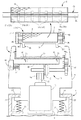
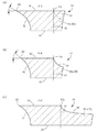
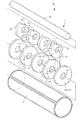
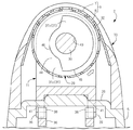
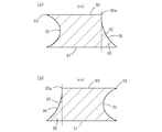
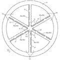
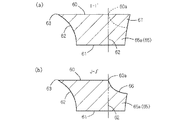
本発明の第1実施例に係る電気かみそりを構成する内刃の構造を示す説明図である。It is explanatory drawing which shows the structure of the inner blade which comprises the electric razor which concerns on 1st Example of this invention. 第1実施例に係る電気かみそりの概略を示す説明図である。It is explanatory drawing which shows the outline of the electric shaver which concerns on 1st Example. 電気かみそりの上部構造を示す縦断側面図である。It is a vertical side view which shows the upper structure of an electric razor. 電気かみそりの上部構造を示す分解図である。It is an exploded view which shows the upper structure of an electric razor. 電気かみそりを構成する内刃の構成を示す平面図である。It is a top view which shows the structure of the inner blade which comprises an electric razor. (a)は図1のA−A’断面図、(b)は図1のB−B’断面図、(c)は図1のC−C’断面図である。1A is a cross-sectional view taken along the line A-A ′ of FIG. 1, FIG. 1B is a cross-sectional view taken along the line B-B ′ of FIG. 1, and FIG. 内刃の構造を説明するための斜視図である。It is a perspective view for demonstrating the structure of an inner blade. 内刃の構造を説明するための分解斜視図である。It is a disassembled perspective view for demonstrating the structure of an inner blade. 本発明の第2実施例に係る電気かみそりの上部構造を示す縦断側面図である。It is a vertical side view which shows the upper structure of the electric shaver which concerns on 2nd Example of this invention. 本発明の第3実施例に係る電気かみそりを構成する内刃の構造を示す分解斜視図である。It is a disassembled perspective view which shows the structure of the inner blade which comprises the electric shaver which concerns on 3rd Example of this invention. 内刃の縦断側面図である。It is a vertical side view of an inner blade. 本発明の第4実施例に係る電気かみそりの概略を示す説明図である。It is explanatory drawing which shows the outline of the electric shaver which concerns on 4th Example of this invention. 電気かみそりを構成する内刃の構成を示す平面図である。It is a top view which shows the structure of the inner blade which comprises an electric razor. 内刃の構造を示す説明図である。It is explanatory drawing which shows the structure of an inner blade. (a)は図14のD−D’断面図、(b)は図14のE−E’断面図、(c)は図14のF−F’断面図である。14A is a cross-sectional view taken along the line D-D ′ of FIG. 14, FIG. 14B is a cross-sectional view taken along the line E-E ′ of FIG. 14, and FIG. 第5実施例に係る電気かみそりを構成する内刃の構成を示す平面図である。It is a top view which shows the structure of the inner blade which comprises the electric razor which concerns on 5th Example. (a)は図16のG−G’断面図、(b)は図16のH−H’断面図である。(A) is G-G 'sectional drawing of FIG. 16, (b) is H-H' sectional drawing of FIG. 本発明の第6実施例に係る電気かみそりの概略を示す説明図である。It is explanatory drawing which shows the outline of the electric shaver which concerns on 6th Example of this invention. 電気かみそりを構成する内刃の構成を示す平面図である。It is a top view which shows the structure of the inner blade which comprises an electric razor. 内刃の頂点部の拡大図である。It is an enlarged view of the vertex part of an inner blade. (a)は図20のI−I’断面図、(b)は図20のJ−J’断面図である。20A is a cross-sectional view taken along the line I-I ′ of FIG. 20, and FIG. 20B is a cross-sectional view taken along the line J-J ′ of FIG. 20.

(第1実施例) 図1乃至図8に、本発明に係る電気かみそりをロータリー式の電気かみそりに適用した第1実施例を示す。なお、本発明における前後、左右、上下とは、図2および図3に示す交差矢印と、各矢印の近傍に表記した前後、左右、上下の表示に従う。 First Embodiment FIGS. 1 to 8 show a first embodiment in which the electric razor according to the present invention is applied to a rotary electric razor. In the present invention, “front / rear”, “left / right”, and “up / down” follow the cross arrows shown in FIGS.

図2、図3および図4に示すように、本実施例に係る電気かみそりは、本体部1と、後述するフロート機構Fを介して本体部1で支持されるかみそりヘッド2とで構成される。本体部1の前面には、後述するモーター10をオン/オフ操作するための電源スイッチ3が配置され、本体部1の後面側にはきわ剃りユニット(図示せず)が配置されている。本体部1の内部には、2次電池4や図外の回路基板などが組み込まれている。   As shown in FIGS. 2, 3, and 4, the electric razor according to the present embodiment includes a main body 1 and a razor head 2 that is supported by the main body 1 via a float mechanism F described later. . A power switch 3 for turning on / off a motor 10 described later is disposed on the front surface of the main body 1, and a shaving unit (not shown) is disposed on the rear surface side of the main body 1. Inside the main body 1, a secondary battery 4 and a circuit board (not shown) are incorporated.

図4に示すように、かみそりヘッド2は、ヘッドケース5と、ヘッドケース5の下面に固定されるモーターホルダー6などを主な外殻構造体にして構成される。ヘッドケース5には、外刃7と内刃8とからなる切断部9と、モーター10の回転動力を内刃8に伝動する内刃駆動機構11などが設けられている。モーターホルダー6内には、出力軸12が縦方向に向く姿勢でモーター10が収容されている。内刃駆動機構11は、モーター10の縦軸まわりの回転動力を左右軸まわりの回転動力に変換する出力ギヤ14およびフェースギヤ15と、フェースギヤ15の回転動力を軸本体30に固定した受動ギヤ16に伝動するギヤトレイン17とで構成される。モーター10の駆動力を受けて、内刃8は図3において矢印で示す向き(反時計回転方向)に回転駆動される。   As shown in FIG. 4, the razor head 2 includes a head case 5 and a motor holder 6 fixed to the lower surface of the head case 5 as main outer shell structures. The head case 5 is provided with a cutting portion 9 composed of an outer blade 7 and an inner blade 8, an inner blade driving mechanism 11 that transmits the rotational power of a motor 10 to the inner blade 8, and the like. The motor 10 is accommodated in the motor holder 6 with the output shaft 12 oriented in the vertical direction. The inner blade drive mechanism 11 includes an output gear 14 and a face gear 15 that convert rotational power around the vertical axis of the motor 10 into rotational power around the left and right axes, and a passive gear that fixes the rotational power of the face gear 15 to the shaft body 30. 16 and a gear train 17 that transmits to 16. In response to the driving force of the motor 10, the inner blade 8 is rotationally driven in the direction indicated by the arrow in FIG. 3 (counterclockwise direction).

図4に示すように、かみそりヘッド2を支持するフロート機構Fは、本体ケース1の上端に内向きに突設形成されて、かみそりヘッド2の抜け止めを図る規制座20と、該規制座20の下方に配置されたばね受座21と、モーターホルダー6の底部に外向きに突設形成された左右一対の装着片22・22と、これらばね受座21と装着片22との間に配置された左右一対の圧縮コイル形のフロートばね23・23とで構成される。このフロートばね23・23でモーターホルダー6を押し上げ付勢することにより、かみそりヘッド2の全体は少なくとも上下に移動可能に、本実施形態に係るフロート機構においては、上下動だけでなく、左右傾動可能に支持されている。かみそりヘッド2の上方への移動限界は、装着片22が規制座20の下面に接触することで規制される。   As shown in FIG. 4, the float mechanism F that supports the razor head 2 is formed so as to project inwardly at the upper end of the main body case 1, and the restriction seat 20 that prevents the razor head 2 from coming off, and the restriction seat 20. Is disposed between the spring seat 21 and the mounting piece 22, the pair of left and right mounting pieces 22, 22 projecting outwardly from the bottom of the motor holder 6. And a pair of left and right compression coil type float springs 23 and 23. By pushing up and urging the motor holder 6 with the float springs 23 and 23, the entire razor head 2 can be moved up and down at least. In the float mechanism according to the present embodiment, not only the vertical movement but also the horizontal tilting is possible. It is supported by. The upper limit of movement of the razor head 2 is regulated by the mounting piece 22 coming into contact with the lower surface of the regulation seat 20.

図4に示すように、外刃7と内刃8とからなる切断部9は、刃ユニット25としてユニット部品化された状態でヘッドケース5に対して脱着可能に装着されている。ヘッドケース5には、刃ユニット25を装着するためのユニット支持台26が形成されており、これら刃ユニット25とヘッドケース5との間には、ユニット支持台26に装着した刃ユニット25を分離不能に固定保持するためのロック構造が設けられている。   As shown in FIG. 4, the cutting portion 9 including the outer blade 7 and the inner blade 8 is detachably attached to the head case 5 in the state of being a unit component as a blade unit 25. A unit support base 26 for mounting the blade unit 25 is formed in the head case 5, and the blade unit 25 mounted on the unit support base 26 is separated between the blade unit 25 and the head case 5. A lock structure is provided for impossible fixed fixing.

刃ユニット25は、シート状の網刃である外刃7と、ロータリー刃構造の内刃8と、これら外刃7と内刃8を支持する支持フレーム(支持体)27と、内刃8の一側端に固定される受動ギヤ16などで構成される。外刃7は、エッチング法あるいは電鋳法で形成されており、その前後縁が支持フレーム27に支持されて、逆U字状に保形されている。回転刃である内刃8は、左右方向に伸びる横軸である軸本体30と、回転軸方向に並ぶ複数のディスク31とで構成される回転軸体29と、ディスク31の周囲に固定された切断刃32とで構成される。   The blade unit 25 includes an outer blade 7 that is a sheet-like mesh blade, an inner blade 8 having a rotary blade structure, a support frame (support) 27 that supports the outer blade 7 and the inner blade 8, and the inner blade 8. It is comprised with the passive gear 16 etc. which are fixed to one side end. The outer blade 7 is formed by an etching method or an electroforming method, and its front and rear edges are supported by a support frame 27 and are held in an inverted U shape. The inner blade 8 that is a rotary blade is fixed around the disc 31 and a rotary shaft body 29 that is composed of a shaft body 30 that is a horizontal axis extending in the left-right direction and a plurality of discs 31 arranged in the direction of the rotary shaft. And a cutting blade 32.

図4に示すように、支持フレーム27は左右横長のベース壁34と、ベース壁34の左右の両側上面に突設される軸受壁35・35とを一体に備えた、左右に長い逆門形のプラスチック成形品であり、一対の軸受壁35・35に設けた軸受体35a・35aで軸本体30の左右両端部を支持することにより、内刃8を回転自在に支持している。軸受壁35から突出する内刃8の軸本体30には、ギヤトレイン17に噛み合う受動ギヤ16が装着されている。   As shown in FIG. 4, the support frame 27 is an inverted portal shape that is provided with a horizontally long base wall 34 and bearing walls 35, 35 that protrude from both upper surfaces of the left and right sides of the base wall 34. The inner cutter 8 is rotatably supported by supporting the left and right ends of the shaft body 30 with bearing bodies 35a and 35a provided on a pair of bearing walls 35 and 35. A passive gear 16 that meshes with the gear train 17 is mounted on the shaft body 30 of the inner blade 8 protruding from the bearing wall 35.

ロック構造はヘッドケース5内で左右スライド可能に支持されるロック枠36と、ロック枠36をロック付勢するロックばね37と、ロック枠36の上面に突設された左右一対のロック爪38・38と、これらロック爪38・38に対応して、支持フレーム27のベース壁34の下面に設けられる係合爪39・39などで構成する。ロック枠36の側方側にはロック解除用のノブ40が設けられており、このノブ40はヘッドケース5の側面から露出されている。刃ユニット25をヘッドケース5のユニット支持台26に装着した状態では、ユニット支持台26に設けられた通孔41を介してヘッドケース5内に進入した係合爪39が、ロック爪38と係合することで、刃ユニット25はヘッドケース5にロック固定される。この状態からノブ40をロックばね37の付勢力に抗して押込み操作すると、ロック枠36およびロック爪38が右方へスライド移動されるので、ロック爪38と係合爪39との係合を解除して、刃ユニット25をヘッドケース5のユニット支持台26から取り外すことができる。   The lock structure includes a lock frame 36 that is slidably supported in the head case 5, a lock spring 37 that biases the lock frame 36, and a pair of left and right lock claws 38 that protrude from the upper surface of the lock frame 36. 38, and engaging claws 39, 39 provided on the lower surface of the base wall 34 of the support frame 27 corresponding to the lock claws 38, 38. A lock release knob 40 is provided on the side of the lock frame 36, and the knob 40 is exposed from the side surface of the head case 5. When the blade unit 25 is mounted on the unit support base 26 of the head case 5, the engaging claw 39 that has entered the head case 5 through the through hole 41 provided in the unit support base 26 is engaged with the lock claw 38. By combining, the blade unit 25 is locked and fixed to the head case 5. When the knob 40 is pushed from this state against the urging force of the lock spring 37, the lock frame 36 and the lock claw 38 are slid to the right, so that the lock claw 38 and the engagement claw 39 are engaged. The blade unit 25 can be removed from the unit support 26 of the head case 5 by releasing.

上述のように、内刃8は、回転軸体29と、回転軸体29に固定される円筒状の切断刃32とで構成される。より具体的には、図8に示すように、回転軸体29は、軸本体30と、軸本体30に圧嵌固定される計9個のディスク31とで構成される。ディスク31は円盤状の5枚の支持ディスク31aと、切欠き44を備える偏心ディスク31bとで構成されており、回転軸方向に沿って支持ディスク31aと偏心ディスク31bとが交互に配置されている。このような偏心ディスク31bを内刃8に設けることにより、内刃8に起振構造を付与することができる。   As described above, the inner blade 8 includes the rotary shaft body 29 and the cylindrical cutting blade 32 fixed to the rotary shaft body 29. More specifically, as shown in FIG. 8, the rotary shaft body 29 includes a shaft main body 30 and a total of nine disks 31 that are press-fitted and fixed to the shaft main body 30. The disk 31 includes five disk-shaped support disks 31a and eccentric disks 31b having notches 44. The support disks 31a and the eccentric disks 31b are alternately arranged along the rotation axis direction. . By providing such an eccentric disk 31 b on the inner blade 8, a vibration generating structure can be imparted to the inner blade 8.

軸本体30は丸軸状のマルテンサイト系のステンレス鋼材である。支持ディスク31aはオーステナイト系のステンレス鋼材からなる板材に打抜き加工を施して円盤状に形成してなるものであり、その中央には軸本体30の挿通を許す装填穴43が形成されている。支持ディスク31aの周面は、切断刃32を受ける刃受面とされており、この刃受面に円筒状の切断刃32が溶接固定される。   The shaft body 30 is a round shaft-shaped martensitic stainless steel material. The support disk 31a is formed by punching a plate made of an austenitic stainless steel material into a disk shape, and a loading hole 43 that allows the shaft body 30 to be inserted is formed in the center thereof. The peripheral surface of the support disk 31a is a blade receiving surface that receives the cutting blade 32, and the cylindrical cutting blade 32 is fixed by welding to the blade receiving surface.

偏心ディスク31bは、支持ディスク31aよりも小径に設定された周面を備える円盤を基体として、該円盤の一部に扇形の切欠き44を形成してなるものであり、支持ディスク31aよりも小径の周面を有する大径部45と、該周面よりも小径の周面を有する小径部46とを備える。偏心ディスク31bも支持ディスク31aと同様に、オーステナイト系のステンレス板材に打抜き可能を施してなるものである。偏心ディスク31bには、支持ディスク31aと同様の装填穴43が設けられている。以上のような偏心ディスク31bは、重心が軸本体30の中心から離れた偏心位置に位置する状態で、軸本体30の回転に伴って偏心回転される。   The eccentric disk 31b is formed by forming a disk-shaped notch 44 in a part of the disk having a peripheral surface set to have a smaller diameter than the support disk 31a, and having a smaller diameter than the support disk 31a. A large-diameter portion 45 having a peripheral surface and a small-diameter portion 46 having a peripheral surface having a smaller diameter than the peripheral surface. Similarly to the support disk 31a, the eccentric disk 31b is formed by punching an austenitic stainless steel plate. The eccentric disk 31b is provided with a loading hole 43 similar to the support disk 31a. The eccentric disk 31b as described above is eccentrically rotated with the rotation of the shaft body 30 in a state where the center of gravity is located at an eccentric position away from the center of the shaft body 30.

なお、これら支持ディスク31aは、ステンレス製の所定の直径値の丸棒に切削加工を施して、所定の直径値の施削ブランクを形成したのち、得られた施削ブランクの中央に施削加工あるいはドリル加工を施して装填穴43を形成し、最後に、得られた長尺のブランクを突っ切りバイトで所定の幅に切断して作成することができる。支持ディスク31aはステンレス板材にエッチングを施して作成することもできる。   The support disks 31a are cut into a round bar having a predetermined diameter value made of stainless steel to form a cutting blank having a predetermined diameter value, and then the centering of the obtained cutting blank is performed. Alternatively, the loading hole 43 can be formed by drilling, and finally, the obtained long blank can be cut and cut into a predetermined width with a cut-off tool. The support disk 31a can also be formed by etching a stainless steel plate.

偏心ディスク31bは、上述の支持ディスク31aの作成方法と同様に、所定の直径値の施削ブランクの中央に装填穴43を形成したのち、該装填穴43の形成に前後して、施削ブランクの周囲にブローチ加工を施して切欠き44を形成し、最後に、得られた長尺のブランクを突っ切りバイトで所定の幅に切断して作成することができる。偏心ディスク31bはステンレス板材にエッチングを施して作成することもできる。   The eccentric disc 31b is formed by forming the loading hole 43 in the center of the cutting blank having a predetermined diameter value, and then forming the cutting blank before and after the formation of the loading hole 43, in the same manner as in the method of creating the support disk 31a. A notch 44 is formed by performing a broaching process on the periphery, and finally, the obtained long blank is cut into a predetermined width with a cut-off tool. The eccentric disk 31b can also be formed by etching a stainless steel plate.

このように偏心ディスク31bの重心が軸本体30に対して偏心されていると、モーター10の駆動力を受けて内刃8が軸本体30まわりに回転駆動されたときに、偏心ディスク31bの慣性モーメントによって振動を発生させて、内刃8を強制的に振動させることができる。また、かかる内刃8の振動により、外刃7を含むかみそりヘッド2も前後、上下方向を含む、偏心ディスク31bの回転平面の全方位方向へ振動させることができる。このとき、かみそりヘッド2はフロート構造で支持されているため、かみそりヘッド2には浮動方向(上下方向)へ振動する傾向が生じ、かみそりヘッド2の浮動動作と、偏心ディスク31bによる振動動作とが融合された動きで外刃7に接する肌面を震わせることができる。   Thus, when the center of gravity of the eccentric disk 31b is eccentric with respect to the shaft main body 30, the inertia of the eccentric disk 31b is obtained when the inner blade 8 is rotationally driven around the shaft main body 30 by receiving the driving force of the motor 10. The inner blade 8 can be forced to vibrate by generating vibration by the moment. Further, the razor head 2 including the outer blade 7 can be vibrated in all directions of the rotation plane of the eccentric disk 31b including the front and rear and the vertical direction by the vibration of the inner blade 8. At this time, since the razor head 2 is supported by the float structure, the razor head 2 tends to vibrate in the floating direction (vertical direction), and the floating operation of the razor head 2 and the vibration operation by the eccentric disk 31b occur. The skin surface in contact with the outer blade 7 can be shaken by the combined movement.

上記のような起振構造を備えた電気かみそりによれば、かみそりヘッド2の振動によって肌面に倒れこんだ癖ひげを起こし、あるいは肌面と直交する向きに外刃7を振動させることにより、ひげを皮膚の表面に突出させることができるので、ひげをより速やかに、しかもより短く切断でき(深剃りでき)、従来の一般的な電気かみそりに比べてひげ切断を効果的に行える。さらに、かみそりヘッド2がフロートばね23を含むフロート機構Fで少なくとも上下動可能に支持されているので、かみそりヘッド2を振動させながら、その振動が本体部1へ伝わるのを防止することができる。したがって、本体部1を握る手に振動が伝わるのを確実に防止できる。   According to the electric razor provided with the above-described vibration generating structure, by causing the whiskers to fall down on the skin surface due to the vibration of the razor head 2, or by vibrating the outer blade 7 in a direction perpendicular to the skin surface, Since the beard can be protruded from the surface of the skin, the beard can be cut more quickly and more quickly (shaving can be performed), and the beard can be cut more effectively than a conventional electric shaver. Furthermore, since the razor head 2 is supported by the float mechanism F including the float spring 23 so as to be at least vertically movable, it is possible to prevent the vibration from being transmitted to the main body 1 while vibrating the razor head 2. Therefore, it is possible to reliably prevent vibration from being transmitted to the hand holding the main body 1.

少なくとも上下動可能に支持されたかみそりヘッド2を、上下振動させて肌面を外刃7で震わせることにより深剃りできる利点もある。起振構造で発生した振動を、かみそりヘッド2を介して外刃7に伝え、外刃7に密着する肌面を震わせるので、外刃7を内刃8に密着させた状態のままで、肌面に振動を与えながらひげ切断を行える。つまり、切れ味を維持した状態のままで、肌面を震わせて効果的にひげ切断を行うことができる。また、内刃8の振動に伴って外刃7を共振させることができるので、内刃8のみが振動する形態では不可避となる、外刃7に対する内刃8の摺動抵抗が大きくなることに起因する両刃7・8の摩耗を抑えることができる。したがって、両刃7・8の耐久性が低下することを効果的に防ぐことができる。   There is also an advantage that at least the razor head 2 supported so as to be movable up and down can be shaved by vibrating up and down and shaking the skin surface with the outer blade 7. The vibration generated in the vibration generating structure is transmitted to the outer blade 7 via the razor head 2 and the skin surface that is in close contact with the outer blade 7 is vibrated, so that the skin remains in the state in which the outer blade 7 is in close contact with the inner blade 8. Cutting whiskers while applying vibration to the surface. That is, whiskers can be effectively cut by shaking the skin surface while maintaining the sharpness. Further, since the outer blade 7 can resonate with the vibration of the inner blade 8, the sliding resistance of the inner blade 8 with respect to the outer blade 7 becomes inevitable when only the inner blade 8 vibrates. The resulting wear of the double blades 7 and 8 can be suppressed. Accordingly, it is possible to effectively prevent the durability of the double blades 7 and 8 from being lowered.

また、内刃8に切欠き44を備える偏心ディスク31bを設けると、内刃8を水中で回転駆動させたとき、切断刃32の内部に水流を発生させることができる。この水流を切断刃32の内面、回転軸体29に衝突させることにより、これらに付着する付着物を効果的に除去できる。切断刃32の内部から水流を発生させるので、切断刃32の内面や回転軸体29に付着した付着物を効果的に除去できる。別途水流攪拌具を設ける形態に比べて、水流攪拌機構の構造の簡素化を図って、電気かみそりの製造コストを低減できる。   In addition, when the eccentric disk 31b having the notch 44 is provided in the inner blade 8, a water flow can be generated inside the cutting blade 32 when the inner blade 8 is rotationally driven in water. By making this water flow collide with the inner surface of the cutting blade 32 and the rotary shaft 29, the deposits attached to these can be effectively removed. Since the water flow is generated from the inside of the cutting blade 32, the deposits attached to the inner surface of the cutting blade 32 and the rotary shaft body 29 can be effectively removed. Compared with a configuration in which a water stirrer is separately provided, the structure of the water stirrer mechanism can be simplified, and the manufacturing cost of the electric shaver can be reduced.

切断刃32は、マルテンサイト系のステンレス板材にエッチング加工を施し、さらにロール加工(塑性加工)を施して円筒状に形成される。図5に示すように、エッチング加工を施したシート状ブランク50には、リブ状の小刃51の一群と、小刃51で囲まれる菱形の刃穴53の一群と、これらの周囲を囲む周枠54とが形成されており、展開状態のシート状ブランク50の全体はエキスパンドメタル状の外観を呈している。小刃51は、第1小刃51aの一群と、該第1小刃51aと異なる方向に伸びる第2小刃51bの一群とで構成される。   The cutting blade 32 is formed in a cylindrical shape by performing etching processing on a martensitic stainless steel plate and further performing roll processing (plastic processing). As shown in FIG. 5, the etched sheet-like blank 50 includes a group of rib-shaped small blades 51, a group of diamond-shaped blade holes 53 surrounded by the small blades 51, and a periphery surrounding these. The whole of the unfolded sheet-like blank 50 has an expanded metal appearance. The small blade 51 includes a group of first blades 51a and a group of second blades 51b extending in a direction different from the first blades 51a.

第1小刃51aの一群と第2小刃51bの一群とは、それぞれ回転軸体29の中心軸に対して傾斜する状態で形成されている。換言すれば、図1に示すように、第1小刃51aの一群と第2小刃51bの一群とは、共に内刃8の回転方向(図1において白抜き矢印で示す方向)に対して傾斜する状態で形成されている。各刃穴53を区画する第2小刃51bの内縁は平行とされているのに対して、第1小刃51aの内縁は非平行に位置ズレして形成されている。以上より、刃穴53は、第2小刃51bで区画される短辺が平行で、第1小刃51aで区画される長辺が位置ズレした千鳥状に配置されている。換言すれば、第2小刃51bの伸び方向で規定される小刃穴の一群を「列」としたとき、第1小刃51aで区画される刃穴53の長辺位置は、隣り合う「列」を構成する刃穴53の長辺位置と一致しておらず、各刃穴53は、隣り合う「列」を構成する刃穴53に対して長辺位置が相互にずれた千鳥状に配置されている。このように、各刃穴53を千鳥状に配置することにより、隣り合う「列」を構成する刃穴53との間には、第1小刃51aと第2小刃51bとが交差する三叉路状の交差部55が形成される。   The group of first blades 51 a and the group of second blades 51 b are formed so as to be inclined with respect to the central axis of the rotating shaft body 29. In other words, as shown in FIG. 1, the group of first blades 51 a and the group of second blades 51 b are both relative to the rotation direction of the inner blade 8 (the direction indicated by the white arrow in FIG. 1). It is formed in an inclined state. The inner edge of the second small blade 51b that defines each blade hole 53 is parallel, whereas the inner edge of the first small blade 51a is formed non-parallelly shifted. As described above, the blade holes 53 are arranged in a staggered manner in which the short sides defined by the second small blades 51b are parallel and the long sides defined by the first small blades 51a are misaligned. In other words, when a group of small blade holes defined by the extending direction of the second small blade 51b is defined as “row”, the long side positions of the blade holes 53 defined by the first small blade 51a are adjacent to each other. It does not coincide with the long side positions of the blade holes 53 constituting the “row”, and each blade hole 53 has a zigzag shape in which the long side positions are shifted from each other with respect to the blade holes 53 constituting the adjacent “row”. Has been placed. In this way, by arranging the blade holes 53 in a staggered manner, the first and second blades 51a and 51b intersect each other between the blade holes 53 constituting the adjacent "rows". A crossing portion 55 is formed.

図1に示すように、各刃穴53の四周縁のうち、内刃8の駆動方向の下流側に位置する二つの周縁は、波状に屈曲されている。より具体的には、各刃穴53の下流側切断領域に位置する第1小刃51a、および第2小刃51bは、内凹み湾曲状の凹縁部56と外凸湾曲状の凸縁部57とが交互に連続する波形の屈曲形状に形成されている。これに対して、各小刃の上流側切断領域に位置する第1小刃51a、および第2小刃51bはストレート状に形成されている。   As shown in FIG. 1, of the four peripheral edges of each blade hole 53, two peripheral edges positioned on the downstream side in the driving direction of the inner blade 8 are bent in a wave shape. More specifically, the first small blade 51a and the second small blade 51b located in the downstream cutting region of each blade hole 53 include an inner concave curved concave edge portion 56 and an outer convex curved convex edge portion. 57 is formed in a bent shape having a waveform that is alternately continuous. On the other hand, the 1st small blade 51a and the 2nd small blade 51b which are located in the upstream cutting area | region of each small blade are formed in straight shape.

図6(a)〜(c)に示すように、小刃51の基本的な断面形状は、外刃7の内面に接する剪断面60と、剪断面60の下方側に位置する非剪断面61と、これら面60・61の側縁間を?ぐ側面62とで構成される。剪断面60の下流側切断領域に位置する側縁には、剪断面60と側面62とに挟まれる鋭角の切刃63が形成され、この切刃63が外刃7と協同してひげを切断する。以上のように、小刃51(第1小刃51a、および第2小刃51b)の下流側切断領域を、平面視で凹縁部56と凸縁部57とが交互に連続する波形に形成すると、これら凹縁部56と凸縁部57との間に形成される傾斜する切刃63により、ひげを引き切りすることができるので、シャープな切れ味が発揮される。   As shown in FIGS. 6A to 6C, the basic cross-sectional shape of the small blade 51 includes a shearing surface 60 in contact with the inner surface of the outer blade 7 and a non-shearing surface 61 positioned on the lower side of the shearing surface 60. And a side surface 62 extending between the side edges of these surfaces 60 and 61. An acute angle cutting blade 63 sandwiched between the shear surface 60 and the side surface 62 is formed on the side edge located in the downstream cutting region of the shear surface 60, and the cutting blade 63 cooperates with the outer blade 7 to cut the beard. To do. As described above, the downstream cutting region of the small blade 51 (the first small blade 51a and the second small blade 51b) is formed in a waveform in which the concave edge portions 56 and the convex edge portions 57 are alternately continuous in a plan view. Then, since the beard can be cut off by the inclined cutting blade 63 formed between the concave edge portion 56 and the convex edge portion 57, a sharp sharpness is exhibited.

このように、小刃51(第1小刃51a、および第2小刃51b)の下流側切断領域を波状に湾曲させて、凹縁部56を形成すると、凹縁部56を形成した分だけ、小刃51の断面面積が小さくなり、小刃51の構造強度が低下することが避けられない(図6(b)参照)。より具体的には、縦断側面視における、剪断面60の側縁60aで規定される小刃51の断面面積が、凹縁部56を形成した分だけ小さくなるため、その構造強度が低下することが避けられない。かかる不具合を解消するため、図1、図6(b)および図7に示すように、剪断面60を挟んで切刃63の形成箇所の反対側に位置する側面62の下方部分に、剪断面60の側縁60aよりも側方側に突出する第1補強体65aを設けている。これにより、第1補強体65aの分だけ小刃51の断面面積を大きくすることができるので、凹縁部56を形成したことに伴う断面面積の低下を補って、小刃51の構造強度が低下することを防ぐことができる。また、小刃51の曲げ強度を向上して、内刃8の耐久性を向上できる。   In this way, if the downstream cutting region of the small blade 51 (the first small blade 51a and the second small blade 51b) is curved in a wave shape to form the concave edge portion 56, the amount corresponding to the amount of the concave edge portion 56 formed. The cross-sectional area of the small blade 51 is reduced, and the structural strength of the small blade 51 is inevitably lowered (see FIG. 6B). More specifically, since the cross-sectional area of the small blade 51 defined by the side edge 60a of the shearing surface 60 in the longitudinal side view is reduced by the amount of the concave edge portion 56, the structural strength is reduced. Is inevitable. In order to eliminate such a problem, as shown in FIGS. 1, 6B and 7, a shear surface is formed on a lower portion of a side surface 62 which is located on the opposite side of the formation position of the cutting blade 63 with the shear surface 60 interposed therebetween. A first reinforcing body 65a that protrudes to the side of the side edge 60a of the 60 is provided. As a result, the cross-sectional area of the small blade 51 can be increased by the amount of the first reinforcing body 65a. It can be prevented from lowering. Further, the bending strength of the small blade 51 can be improved, and the durability of the inner blade 8 can be improved.

また、上記のように、側面62の下方部分に剪断面60の側縁60aよりも側方側に突出させて第1補強体65aを形成したため、該第1補強体65aの上方には、剪断面60に対して段落ちした段落ち空間66が形成される。このため、第1補強体65aの上面が外刃7に接触することは無く、第1補強体65aを設けたことに伴って、内刃8の外刃7に対する摺動抵抗が増加する不都合は生じない。   Further, as described above, since the first reinforcing body 65a is formed in the lower portion of the side surface 62 so as to protrude from the side edge 60a of the shearing surface 60 to the side, the shear strength 60a is sheared above the first reinforcing body 65a. A step-down space 66 stepped down with respect to the surface 60 is formed. For this reason, the upper surface of the 1st reinforcement body 65a does not contact the outer blade 7, and the inconvenience that the sliding resistance with respect to the outer blade 7 of the inner blade 8 increases by providing the 1st reinforcement body 65a. Does not occur.

図1、図6(a)および図7に示すように、第1補強体65aの上面には、段落ち空間66を部分的に埋めるように縦リブ67が形成されている。縦リブ67の上面位置は、剪断面60と一致している。このように縦リブ67を設けると、小刃51の断面面積をさらに大きくすることができるので、小刃51の構造強度のさらなる向上が期待できる。また、縦リブ67は、第1補強体65aに部分的に形成されているため、縦リブ67を設けたことに伴う内刃8の摺動抵抗の増加は僅かである。   As shown in FIGS. 1, 6A, and 7, vertical ribs 67 are formed on the upper surface of the first reinforcing body 65a so as to partially fill the step-down space 66. As shown in FIG. The upper surface position of the vertical rib 67 coincides with the shearing surface 60. If the vertical rib 67 is provided in this way, the cross-sectional area of the blade 51 can be further increased, so that further improvement in the structural strength of the blade 51 can be expected. Moreover, since the vertical rib 67 is partially formed in the 1st reinforcement body 65a, the increase in the sliding resistance of the inner blade 8 accompanying provision of the vertical rib 67 is slight.

図6(c)に示すように、第1小刃51aと第2小刃51bとが交差する三叉路状の交差部55の下方には、第1補強体65aと同様に、剪断面60の側縁60aよりも側方側に突出する第2補強体65bが設けられている。このように交差部55に進入するように第2補強体65bが設けられていると、この第2補強体65bの分だけ交差部55の断面面積を大きくすることができるので、当該交差部55の構造強度を大きくすることができる。なお、第1補強体65aと同様に、第2補強体65bも側面62の下方部分に設けられているため、第2補強体65bが外刃7に接触することはなく、摺動抵抗が増加するおそれは無い。   As shown in FIG. 6C, below the three-way intersection 55 where the first small blade 51a and the second small blade 51b intersect, the side of the shear surface 60 is the same as the first reinforcing body 65a. The 2nd reinforcement body 65b which protrudes to the side side rather than the edge 60a is provided. If the second reinforcement body 65b is provided so as to enter the intersection portion 55 in this way, the cross-sectional area of the intersection portion 55 can be increased by the amount of the second reinforcement body 65b. The structural strength of can be increased. In addition, since the 2nd reinforcement body 65b is provided in the lower part of the side surface 62 similarly to the 1st reinforcement body 65a, the 2nd reinforcement body 65b does not contact the outer blade 7, and sliding resistance increases. There is no fear.

図1に示すように、第1補強体65aと第2補強体65bとは連続されている。このように両補強体65a・65bが連続されていると、両補強体65a・65bの分断部分に応力が集中して切断刃32が破損することを効果的に防ぐことができる。   As shown in FIG. 1, the first reinforcing body 65a and the second reinforcing body 65b are continuous. Thus, if both the reinforcement bodies 65a and 65b are continued, it can prevent effectively that stress concentrates on the parting part of both the reinforcement bodies 65a and 65b, and the cutting blade 32 is damaged.

図3に示すように、小刃51の表面には光触媒69が固定されている。かかる光触媒69は、少なくとも第1補強体65aおよび/又は第2補強体65bの上部に固定されている。これによれば、光触媒69に由来する有機物分解作用によって内刃8に付着の有機物を分解できるので、内刃8を衛生的な状態に維持することができる。有機物の酸化や発酵に伴う異臭の発生も解消することができる。   As shown in FIG. 3, a photocatalyst 69 is fixed to the surface of the small blade 51. The photocatalyst 69 is fixed to at least the upper part of the first reinforcing body 65a and / or the second reinforcing body 65b. According to this, since the organic matter adhering to the inner blade 8 can be decomposed by the organic substance decomposing action derived from the photocatalyst 69, the inner blade 8 can be maintained in a sanitary state. Odor generation due to oxidation of organic matter and fermentation can also be eliminated.

(第2実施例) 図9に本発明の第2実施例を示す。この第2実施例では、外刃7と内刃8のそれぞれを、別々にヘッドケース5に装着した点が、先の第1実施例と相違する。すなわち、この第2実施例では、外刃7が外刃ホルダー(外刃支持体)70に保持されており、回転刃である内刃8が内刃ホルダー(内刃支持体)71に保持されており、これら外刃ホルダー70と内刃ホルダー71が、別々にヘッドケース5に装着されている。 Second Embodiment FIG. 9 shows a second embodiment of the present invention. The second embodiment is different from the first embodiment in that each of the outer blade 7 and the inner blade 8 is separately mounted on the head case 5. That is, in the second embodiment, the outer blade 7 is held by the outer blade holder (outer blade support) 70, and the inner blade 8 that is a rotary blade is held by the inner blade holder (inner blade support) 71. The outer blade holder 70 and the inner blade holder 71 are mounted on the head case 5 separately.

この第2実施例においても、先の第1実施例と同様の作用効果を得ることができる。すなわち、モーター10の駆動力を受けて内刃8が軸本体30まわりに回転駆動されたときに、偏心ディスク31bの慣性モーメントによって振動を発生させて、内刃8を強制的に振動させることができる。また、かかる内刃8の振動により、内刃ホルダー71等を介して外刃7を含むかみそりヘッド2も前後、上下方向を含む、偏心ディスク31bの回転平面の全方位方向へ振動させることができる。このとき、かみそりヘッド2はフロート構造で支持されているため、該かみそりヘッド2には、浮動方向(上下方向)へ振動する傾向が生じ、かみそりヘッド2の浮動動作と、偏心ディスク31bによる振動動作とが融合された動きで外刃7に接する肌面を震わせることができる。また、浮動支持されたかみそりヘッド2を、浮動方向へ上下振動させて肌面を外刃7で震わせることにより深剃りできる利点もある。起振構造で発生した振動を、かみそりヘッド5および外刃ホルダー70を介して外刃7に伝え、外刃7に密着する肌面を震わせるので、外刃7を内刃8に密着させた状態のままで、肌面に振動を与えながらひげ切断を行える。つまり、切れ味を維持した状態のままで、肌面を震わせて効果的にひげ切断を行うことができる。また、内外刃8・7を非同期状態で振動させることができるので、内刃8の剪断面60と外刃7の内面との間に微小な隙間を不規則に発生させて、両者間にひげの切断屑が膠着するのを防止できる。これにより、外刃7に対する内刃8の摺動抵抗が大きくなることに起因するモーター10の負荷の上昇を抑えることができる。   In the second embodiment, the same effect as that of the first embodiment can be obtained. That is, when the inner blade 8 is rotationally driven around the shaft body 30 by receiving the driving force of the motor 10, vibration is generated by the moment of inertia of the eccentric disk 31b to forcibly vibrate the inner blade 8. it can. In addition, the razor head 2 including the outer blade 7 can be vibrated in all directions of the rotation plane of the eccentric disk 31b including the front and rear and the vertical direction through the inner blade holder 71 and the like by the vibration of the inner blade 8. . At this time, since the razor head 2 is supported by the float structure, the razor head 2 tends to vibrate in the floating direction (up and down direction), and the razor head 2 floats and vibrates by the eccentric disk 31b. It is possible to vibrate the skin surface in contact with the outer blade 7 by the combined movement. In addition, there is an advantage that the razor head 2 that is supported in a floating manner can be shaved by vibrating it up and down in the floating direction and shaking the skin surface with the outer blade 7. The vibration generated in the vibration generating structure is transmitted to the outer blade 7 via the razor head 5 and the outer blade holder 70, and the skin surface in close contact with the outer blade 7 is vibrated, so that the outer blade 7 is in close contact with the inner blade 8. The beard can be cut while applying vibration to the skin surface. That is, whiskers can be effectively cut by shaking the skin surface while maintaining the sharpness. Further, since the inner and outer blades 8 and 7 can be vibrated in an asynchronous state, a minute gap is irregularly generated between the shearing surface 60 of the inner blade 8 and the inner surface of the outer blade 7, and the whisker is between them. It is possible to prevent the cutting waste from sticking. Thereby, the raise of the load of the motor 10 resulting from the sliding resistance of the inner blade 8 with respect to the outer blade 7 becoming large can be suppressed.

(第3実施例) 図10および図11に本発明の第3実施例を示す。この第3実施例では、真円盤状の支持ディスク31aを廃して、回転軸体29を構成するディスク31を、切欠き44を有する偏心ディスク31bのみで構成した点が先の第1実施例と相違する。この第3実施例の偏心ディスク31bは、円盤状のディスクに対して内凹み状の切欠き44を形成してなるものであり、各偏心ディスク31bの重心は軸本体30に対して偏心されている。偏心ディスク31bの最外周面は、切断刃32を受ける刃受面とされており、この刃受面に円筒状の切断刃32が溶接固定される。 Third Embodiment FIGS. 10 and 11 show a third embodiment of the present invention. In the third embodiment, the disc-shaped support disk 31a is eliminated, and the disk 31 constituting the rotary shaft 29 is constituted only by the eccentric disk 31b having the notch 44, which is different from the first embodiment. Is different. The eccentric disk 31b of the third embodiment is formed by forming an indented notch 44 with respect to the disk-shaped disk, and the center of gravity of each eccentric disk 31b is eccentric with respect to the shaft body 30. Yes. The outermost peripheral surface of the eccentric disk 31b is a blade receiving surface that receives the cutting blade 32, and the cylindrical cutting blade 32 is fixed to the blade receiving surface by welding.

本実施例においては、回転軸体29は、5個の偏心ディスク31bを備えるものとなっている。軸本体30に対する偏心ディスク31bの周方向の固定姿勢は、切欠き44の位置が一致する同一姿勢とされている。このように各偏心ディスク31bの周方向の固定姿勢を同一姿勢としていると、各偏心ディスク31bの偏心回転によって生じる偏心ディスク31bの振動を同調させることができるので、より大きな振動モーメントを内刃8と外刃7に付与することができる。   In the present embodiment, the rotating shaft 29 is provided with five eccentric disks 31b. The fixed posture in the circumferential direction of the eccentric disk 31b with respect to the shaft body 30 is the same posture in which the positions of the notches 44 coincide. As described above, when the fixed postures in the circumferential direction of the eccentric disks 31b are the same, the vibrations of the eccentric disks 31b generated by the eccentric rotation of the eccentric disks 31b can be synchronized, so that a larger vibration moment is applied to the inner blade 8. And can be applied to the outer blade 7.

(第4実施例) 図12〜図15に本発明の第4実施例を示す。この第4実施例では、第1実施例に係る小刃51の形態をレシプロ式の電気かみそりに適用している。図12において、電気かみそりは、本体部1と、フロート機構Fを介して本体部1で支持されるかみそりヘッド2とで構成される。本体部1の前面には、モーター10をオン/オフ操作するための電源スイッチ3が配置されて、本体部1の後面側にはきわ剃りユニット(図示せず)が配置されている。本体部1の内部には、2次電池4や図外の回路基板などが組み込まれている。 (Fourth Embodiment) FIGS. 12 to 15 show a fourth embodiment of the present invention. In the fourth embodiment, the form of the blade 51 according to the first embodiment is applied to a reciprocating electric shaver. In FIG. 12, the electric razor is composed of a main body 1 and a razor head 2 supported by the main body 1 via a float mechanism F. A power switch 3 for turning on / off the motor 10 is disposed on the front surface of the main body 1, and a shaving unit (not shown) is disposed on the rear surface side of the main body 1. Inside the main body 1, a secondary battery 4 and a circuit board (not shown) are incorporated.

かみそりヘッド2は、ヘッドケース5と、その下部に固定されるモーター10と、かみそりヘッド2の上部に配置される切断部9と、モーター10の動力を切断部9に伝動する駆動構造と、ヘッドケース5に対して着脱される外刃ホルダー70などで構成される。かみそりヘッド2は、本体部1との間に設けられたフロート機構Fにより、上下動可能に支持されている。かかるフロート機構Fの構造は、第1実施例と同様である。   The razor head 2 includes a head case 5, a motor 10 fixed to the lower portion thereof, a cutting portion 9 disposed on the upper portion of the razor head 2, a drive structure for transmitting the power of the motor 10 to the cutting portion 9, and a head. The outer blade holder 70 is attached to and detached from the case 5. The razor head 2 is supported by a float mechanism F provided between the razor head 2 and the main body 1 so as to be movable up and down. The structure of the float mechanism F is the same as that of the first embodiment.

切断部9は、左右横長の外刃7と、外刃7の内面に沿って左右に往復駆動される左右横長の内刃8とで構成される。外刃7は電鋳法或いはエッチング法で形成されるシート状の網刃からなり、先の外刃ホルダー70で逆U字状に保形されている。内刃8は、図13に示すような内刃ブランク75にプレス加工を施して、逆U字状に折り曲げたスリット刃であり、内刃ホルダー71に固定されて逆U字状に保形されている。内刃ブランク75はエッチング法で形成される。   The cutting part 9 includes a laterally long outer blade 7 and a laterally long inner blade 8 that is driven to reciprocate left and right along the inner surface of the outer blade 7. The outer blade 7 is a sheet-like mesh blade formed by electroforming or etching, and is held in an inverted U shape by the outer blade holder 70 at the tip. The inner blade 8 is a slit blade that is pressed into an inner blade blank 75 as shown in FIG. 13 and bent into an inverted U shape, and is fixed to the inner blade holder 71 and held in an inverted U shape. ing. The inner blade blank 75 is formed by an etching method.

内刃8を往復駆動する駆動構造は、モーター10の出力軸12に固定される偏心カム76と、振動子77と、振動子77の上部中央に突設される駆動軸78とで構成される。モーター10の回転動力は、偏心カム76と振動子77とで往復動力に変換され、駆動軸78を介して内刃8に伝動される。内刃8は、振動子77と内刃ホルダー71との間に配置された圧縮コイル形のばね79で押し上げ付勢されており、外刃7の内面に常に密着している。   The drive structure for reciprocating the inner blade 8 includes an eccentric cam 76 that is fixed to the output shaft 12 of the motor 10, a vibrator 77, and a drive shaft 78 that projects from the upper center of the vibrator 77. . The rotational power of the motor 10 is converted into reciprocating power by the eccentric cam 76 and the vibrator 77 and transmitted to the inner blade 8 via the drive shaft 78. The inner blade 8 is pushed up and biased by a compression coil spring 79 disposed between the vibrator 77 and the inner blade holder 71, and is always in close contact with the inner surface of the outer blade 7.

図13に示すように、内刃ブランク75は、左右横長のシート体からなる。内刃ブランク75は、シート体の面壁の前後辺部に沿って、内刃ホルダー71に装着される装着壁80・80を有し、両装着壁80・80の間には、リブ状の小刃51の一群と、小刃51で囲まれる菱形の刃穴53の一群とが形成されており、展開状態のシート状ブランク50の全体はエキスパンドメタル状の外観を呈している。小刃51は、右斜め上方に向かって伸びる第1小刃51aの一群と、左斜め上方に向かって伸びる第2小刃51bの一群とで構成され、刃穴53の間には、第1小刃51aと第2小刃51bとが交差する四叉路状の交差部55が形成される。内刃ブランク75のシート状の長辺部の左右(四隅)には、それぞれ内刃ホルダー71の突起に係合する切欠82がコ字状に形成されている。   As shown in FIG. 13, the inner blade blank 75 is composed of a horizontally long sheet body. The inner blade blank 75 has mounting walls 80 and 80 to be mounted on the inner blade holder 71 along the front and rear sides of the face wall of the sheet body. A group of blades 51 and a group of diamond-shaped blade holes 53 surrounded by the small blades 51 are formed, and the entire sheet-like blank 50 in an unfolded state has an expanded metal appearance. The small blade 51 is composed of a group of first small blades 51 a extending obliquely upward to the right and a group of second small blades 51 b extending obliquely upward to the left. A four-way crossing portion 55 where the small blade 51a and the second small blade 51b intersect is formed. On the left and right sides (four corners) of the sheet-like long side portion of the inner blade blank 75, notches 82 that engage with the protrusions of the inner blade holder 71 are formed in a U shape.

図14に示すように、各刃穴53の四周縁の全ては、波状に屈曲されている。すなわち、各刃穴53を区画する第1小刃51a、および第2小刃51bは、内凹み湾曲状の凹縁部56と外凸湾曲状の凸縁部57とが交互に連続する波形の屈曲形状に形成されている。図15(a)に示すように、小刃51の基本的な断面形状は、外刃7の内面に接する剪断面60と、剪断面60の下方側に位置する非剪断面61と、両面60・61の側縁間を?ぐ側面62とで構成される。剪断面60の左右両側縁のそれぞれには、剪断面60と側面62とに挟まれる切刃63が形成され、これら切刃63が外刃7と協同してひげを切断する。   As shown in FIG. 14, all four peripheral edges of each blade hole 53 are bent in a wave shape. That is, the first small blade 51a and the second small blade 51b that define each blade hole 53 have a waveform in which the concave edge portion 56 having an inner concave curvature and the convex edge portion 57 having an outer convex curvature are alternately continued. It is formed in a bent shape. As shown in FIG. 15A, the basic cross-sectional shape of the small blade 51 includes a shearing surface 60 that contacts the inner surface of the outer blade 7, a non-shearing surface 61 positioned below the shearing surface 60, and both surfaces 60. -It is comprised with the side surface 62 which bridges between 61 side edges. A cutting blade 63 sandwiched between the shearing surface 60 and the side surface 62 is formed on each of the left and right side edges of the shearing surface 60, and the cutting blade 63 cooperates with the outer blade 7 to cut the beard.

このように、小刃51(第1小刃51a、および第2小刃51b)の下流側切断領域を波状に湾曲させて、凹縁部56を形成すると、凹縁部56を形成した分だけ、小刃51の断面面積が小さくなり、小刃51の構造強度が低下することが避けられない(図15(a)参照)。より具体的には、縦断側面視における、剪断面60の側縁60aで規定される小刃51の断面面積が、凹縁部56を形成した分だけ小さくなるため、その構造強度が低下することが避けられない。かかる不具合を解消するため、図14および図15(a)に示すように、剪断面60を挟んで切刃63の形成箇所の反対側に位置する側面62の下方部分に、剪断面60の側縁60aよりも側方側に突出する第1補強体65aを設けている。これにより、第1補強体65aの分だけ小刃51の断面面積を大きくすることができるので、凹縁部56を形成したことに伴う断面面積の低下を補って、小刃51の構造強度が低下することを防ぐことができる。また、小刃51の曲げ強度を向上して、内刃8の耐久性を向上できる。   In this way, if the downstream cutting region of the small blade 51 (the first small blade 51a and the second small blade 51b) is curved in a wave shape to form the concave edge portion 56, the amount corresponding to the amount of the concave edge portion 56 formed. The cross-sectional area of the small blade 51 is reduced, and the structural strength of the small blade 51 is inevitably reduced (see FIG. 15A). More specifically, since the cross-sectional area of the small blade 51 defined by the side edge 60a of the shearing surface 60 in the longitudinal side view is reduced by the amount of the concave edge portion 56, the structural strength is reduced. Is inevitable. In order to eliminate such inconvenience, as shown in FIGS. 14 and 15 (a), the side of the shear surface 60 is located on the lower portion of the side surface 62 located on the opposite side of the formation position of the cutting blade 63 with the shear surface 60 interposed therebetween. The 1st reinforcement body 65a which protrudes to the side side rather than the edge 60a is provided. As a result, the cross-sectional area of the small blade 51 can be increased by the amount of the first reinforcing body 65a. It can be prevented from lowering. Further, the bending strength of the small blade 51 can be improved, and the durability of the inner blade 8 can be improved.

また、上記のように、側面62の下方部分に剪断面60の側縁60aよりも側方側に突出させて第1補強体65aを形成したため、該第1補強体65aの上方には、剪断面60に対して段落ちした段落ち空間66が形成される。このため、第1補強体65aの上面が外刃7に接触することは無く、第1補強体65aを設けたことに伴って、内刃8の外刃7に対する摺動抵抗が増加する不都合は生じない。   Further, as described above, since the first reinforcing body 65a is formed in the lower portion of the side surface 62 so as to protrude from the side edge 60a of the shearing surface 60 to the side, the shear strength 60a is sheared above the first reinforcing body 65a. A step-down space 66 stepped down with respect to the surface 60 is formed. For this reason, the upper surface of the 1st reinforcement body 65a does not contact the outer blade 7, and the inconvenience that the sliding resistance with respect to the outer blade 7 of the inner blade 8 increases by providing the 1st reinforcement body 65a. Does not occur.

図14および図15(b)に示すように、第1小刃51aと第2小刃51bとが交差する交差部55は、外刃7の内面に接する剪断面60と、剪断面60の下方側に位置する非剪断面61と、これら面60・61の側縁間を?ぐ側面62・62とで構成される。剪断面60の両側縁には、剪断面60と側面62とに挟まれる鋭角の切刃63が形成され、この切刃63が外刃7と協同してひげを切断する。図14および図15(c)に示すように、第1小刃51aと第2小刃51bとが交差する四方路状の交差部55の下方には、第1補強体65aと同様に、剪断面60の側縁60aよりも側方側に突出する第2補強体65bが設けられている。このように交差部55に進入するように第2補強体65bが設けられていると、この第2補強体65bの分だけ交差部55の断面面積を大きくすることができるので、当該交差部55の構造強度を大きくすることができる。なお、第1補強体65aと同様に、第2補強体65bも側面62の下方部分に設けられているため、第2補強体65bが外刃7に接触することはなく、摺動抵抗が増加するおそれは無い。   As shown in FIG. 14 and FIG. 15B, the intersecting portion 55 where the first small blade 51 a and the second small blade 51 b intersect includes a shear surface 60 that contacts the inner surface of the outer blade 7, and a lower portion of the shear surface 60. The non-shearing surface 61 located on the side and the side surfaces 62 and 62 extending between the side edges of the surfaces 60 and 61 are configured. At both side edges of the shearing surface 60, an acute angle cutting blade 63 sandwiched between the shearing surface 60 and the side surface 62 is formed, and this cutting blade 63 cooperates with the outer blade 7 to cut the beard. As shown in FIG. 14 and FIG. 15 (c), under the four-way crossing portion 55 where the first small blade 51a and the second small blade 51b intersect, as in the first reinforcing body 65a, shearing is performed. A second reinforcing body 65b that protrudes to the side of the side edge 60a of the surface 60 is provided. If the second reinforcement body 65b is provided so as to enter the intersection portion 55 in this way, the cross-sectional area of the intersection portion 55 can be increased by the amount of the second reinforcement body 65b. The structural strength of can be increased. In addition, since the 2nd reinforcement body 65b is provided in the lower part of the side surface 62 similarly to the 1st reinforcement body 65a, the 2nd reinforcement body 65b does not contact the outer blade 7, and sliding resistance increases. There is no fear.

図14に示すように、第1補強体65aと第2補強体65bとは連続されている。このように両補強体65a・65bが連続されていると、両補強体65a・65bの分断部分に応力が集中して切断刃32が破損することを効果的に防ぐことができる。   As shown in FIG. 14, the first reinforcing body 65a and the second reinforcing body 65b are continuous. Thus, if both the reinforcement bodies 65a and 65b are continued, it can prevent effectively that stress concentrates on the parting part of both the reinforcement bodies 65a and 65b, and the cutting blade 32 is damaged.

(第5実施例) 図16および図17に、本発明の第5実施例に係る電気かみそりを示す。この第5実施例では、内刃8の形態のみが第4実施例と相違する。図16に示すように、内刃8を構成する内刃ブランク75は左右横長のシート体からなり、シート体の面壁の前後辺部に沿って、内刃ホルダー71に装着される装着壁80・80を有し、両装着壁80を?ぐ前後方向に長いリブ状の小刃51と、隣接する小刃51の間に形成された刃穴53とを左右方向へ交互に設けて形成してある。内刃ブランク75のシート状の長辺部の左右(四隅)には、それぞれ内刃ホルダー71の突起に係合する切欠82がコ字状に形成されている。 Fifth Embodiment FIGS. 16 and 17 show an electric razor according to a fifth embodiment of the present invention. In the fifth embodiment, only the form of the inner cutter 8 is different from the fourth embodiment. As shown in FIG. 16, the inner blade blank 75 constituting the inner blade 8 is composed of a horizontally long sheet body, and is mounted on the inner blade holder 71 along the front and rear sides of the face wall of the sheet body. 80, rib-shaped small blades 51 that are long in the front-rear direction across both mounting walls 80, and blade holes 53 formed between adjacent small blades 51 are alternately provided in the left-right direction. is there. On the left and right sides (four corners) of the sheet-like long side portion of the inner blade blank 75, notches 82 that engage with the protrusions of the inner blade holder 71 are formed in a U shape.

図17に示すように、小刃51の基本的な断面形状は、外刃7の内面に接する剪断面60と、剪断面60の下方側に位置する非剪断面61と、両面60・61の側縁間を?ぐ側面62とで構成される。剪断面60の左右両側縁のそれぞれには、剪断面60と側面62とに挟まれる切刃63が形成され、これら切刃63が外刃7と協同してひげを切断する。図16に示すように、小刃51の平面視形状は、内凹み湾曲状の凹縁部56と外湾曲状の凸縁部57とが交互に連続する波形の屈曲形状に形成されている。すなわち、小刃51の切刃63は、凹縁部56と凸縁部57とが交互に連続する波形の屈曲形状とされている。   As shown in FIG. 17, the basic cross-sectional shape of the small blade 51 includes a shearing surface 60 in contact with the inner surface of the outer blade 7, a non-shearing surface 61 positioned below the shearing surface 60, and both surfaces 60 and 61. It is comprised with the side surface 62 which lies between the side edges. A cutting blade 63 sandwiched between the shearing surface 60 and the side surface 62 is formed on each of the left and right side edges of the shearing surface 60, and the cutting blade 63 cooperates with the outer blade 7 to cut the beard. As shown in FIG. 16, the planar view shape of the small blade 51 is formed into a wave-like bent shape in which inner concave curved concave edge portions 56 and outer curved convex edge portions 57 are alternately arranged. That is, the cutting edge 63 of the small blade 51 has a wave-like bent shape in which the concave edge portions 56 and the convex edge portions 57 are alternately continued.

このように、小刃51の切刃63を波状に湾曲させて凹縁部56を形成すると、凹縁部56を形成した分だけ、小刃51の断面面積が小さくなり、小刃51の構造強度が低下することが避けられない。より具体的には、図17(b)に示すように、縦断側面視における、剪断面60の側縁60aで規定される小刃51の断面面積が、凹縁部56を形成した分だけ小さくなるため、その構造強度が低下することが避けられない。かかる不具合を解消するため、本実施例では、図16および図17(a)・(b)に示すように、側面62の下方部分に、剪断面60の側縁よりも側方側に突出する補強体65を設けている。これにより、補強体65の分だけ小刃51の断面面積を大きくすることができるので、凹縁部56を形成したことに伴う断面面積の低下を補って、小刃51の構造強度が低下することを防ぐことができる。また、小刃51の曲げ強度を向上して、内刃8の耐久性を向上できる。   As described above, when the concave edge portion 56 is formed by curving the cutting edge 63 of the small blade 51 in a wavy shape, the cross-sectional area of the small blade 51 is reduced by the amount the concave edge portion 56 is formed. It is inevitable that the strength decreases. More specifically, as shown in FIG. 17B, the cross-sectional area of the small blade 51 defined by the side edge 60 a of the shearing surface 60 in the side view in the longitudinal direction is small as much as the concave edge portion 56 is formed. Therefore, the structural strength is inevitably lowered. In order to eliminate such a problem, in this embodiment, as shown in FIGS. 16 and 17A and 17B, the lower portion of the side surface 62 protrudes to the side of the side edge of the shear surface 60. A reinforcing body 65 is provided. Thereby, since the cross-sectional area of the small blade 51 can be increased by the amount of the reinforcing body 65, the structural strength of the small blade 51 is reduced by compensating for the decrease in the cross-sectional area associated with the formation of the concave edge portion 56. Can be prevented. Further, the bending strength of the small blade 51 can be improved, and the durability of the inner blade 8 can be improved.

また、上記のように、側面62の下方部分に剪断面60の側縁60aよりも側方側に突出させて補強体65を形成したため、該補強体65の上方には、剪断面60に対して段落ちした段落ち空間66が形成される。このため、補強体65の上面が外刃7に接触することは無く、補強体65を設けたことに伴って、内刃8の外刃7に対する摺動抵抗が増加する不都合は生じない。   Further, as described above, the reinforcing body 65 is formed in the lower portion of the side surface 62 so as to protrude from the side edge 60a of the shearing surface 60 to the side, so that the reinforcing body 65 is above the shearing surface 60 above the reinforcing body 65. As a result, a stepped space 66 is formed. For this reason, the upper surface of the reinforcement body 65 does not contact the outer blade 7, and there is no inconvenience that the sliding resistance of the inner blade 8 with respect to the outer blade 7 increases with the provision of the reinforcement body 65.

(第6実施例) 図18乃至図21に本発明の第6実施例を示す。この第6実施例では、第1実施例に係る小刃51の形態を、縦軸まわりに内刃8が回転する内刃回転式の電気かみそりに適用している。図18において電気かみそりは、本体部1と、フロート機構Fを介して本体部1で支持されるかみそりヘッド2とで構成される。本体部1の前面には、モーター10をオン/オフ操作するための電源スイッチ3が配置されている。本体部1の内部には、2次電池4や図外の回路基板などが組み込まれている。 Sixth Embodiment FIGS. 18 to 21 show a sixth embodiment of the present invention. In the sixth embodiment, the form of the small blade 51 according to the first embodiment is applied to an inner blade rotating type electric shaver in which the inner blade 8 rotates around the vertical axis. In FIG. 18, the electric razor is composed of a main body 1 and a razor head 2 supported by the main body 1 via a float mechanism F. A power switch 3 for turning on / off the motor 10 is disposed on the front surface of the main body 1. Inside the main body 1, a secondary battery 4 and a circuit board (not shown) are incorporated.

かみそりヘッド2は、ヘッドケース5と、その下部に固定されるモーター10と、かみそりヘッド2の上部に配置される切断部9と、モーター10の動力を切断部に伝動する駆動構造と、ヘッドケース5に対して着脱される外刃ホルダー70などで構成される。かみそりヘッド2は、本体部1との間に設けられたフロート機構Fにより、上下動可能に支持されている。かかるフロート機構Fの構造は、第1実施例と同様である。   The razor head 2 includes a head case 5, a motor 10 fixed to the lower portion thereof, a cutting portion 9 disposed on the upper portion of the razor head 2, a drive structure for transmitting the power of the motor 10 to the cutting portion, and a head case. 5 is configured with an outer blade holder 70 which is attached to and detached from 5. The razor head 2 is supported by a float mechanism F provided between the razor head 2 and the main body 1 so as to be movable up and down. The structure of the float mechanism F is the same as that of the first embodiment.

切断部9は、ドーム形状に形成した網目状の外刃7と、この外刃7を保持して、ヘッドケース5の上部に着脱自在にねじ込み装着される外刃ホルダー70と、モーター10の出力軸12に接続される内刃ホルダー71と、内刃ホルダー71に保持される内刃8とからなる。モーター10の駆動力を受けて、内刃8は図19に示す白抜き矢印方向に回転駆動される。   The cutting part 9 includes a mesh-shaped outer blade 7 formed in a dome shape, an outer blade holder 70 that holds the outer blade 7 and is detachably screwed onto the top of the head case 5, and an output of the motor 10. The inner blade holder 71 is connected to the shaft 12 and the inner blade 8 is held by the inner blade holder 71. Under the driving force of the motor 10, the inner blade 8 is rotationally driven in the direction of the white arrow shown in FIG.

図18に示すように、内刃8は、側方視において外刃7の内面に沿うドーム形状に形成されており、ドームの頂点部90から等間隔を置いて放射状に伸びる6本のリブ状の小刃51と、小刃51の外端部を保持する円リング状の装着壁91とで構成されており、これら小刃51と装着壁91との間には、計6個の刃穴53が形成されている。かかるドームの頂点部90が、小刃51が交差する交差部55となっている。   As shown in FIG. 18, the inner blade 8 is formed in a dome shape along the inner surface of the outer blade 7 in a side view, and has six ribs extending radially from the apex portion 90 of the dome at equal intervals. And a circular ring-shaped mounting wall 91 that holds the outer end of the small blade 51, and a total of six blade holes are provided between the small blade 51 and the mounting wall 91. 53 is formed. The apex portion 90 of the dome is an intersecting portion 55 where the small blades 51 intersect.

図19および図20に示すように、各小刃51の下流側切断領域に位置する縁辺部は、内凹み湾曲状の凹縁部56と外凸湾曲状の凸縁部57とが交互に連続する波形の屈曲形状に形成されている。これに対して、各小刃51の上流側切断領域に位置する縁辺部は、ストレート状に形成されている。   As shown in FIG. 19 and FIG. 20, in the edge portion located in the downstream cutting region of each small blade 51, a concave edge portion 56 having an inwardly curved shape and a convex edge portion 57 having an outwardly convex curve are alternately continuous. It is formed in a wave-like bent shape. On the other hand, the edge part located in the upstream cutting area | region of each small blade 51 is formed in straight shape.

図21(b)に示すように、小刃51の基本的な断面形状は、外刃7の内面に接する剪断面60と、剪断面60の下方側に位置する非剪断面61と、両面60・61の側縁間を?ぐ側面62とで構成される。剪断面60の下流側切断領域に位置する側縁には、剪断面60と側面62とに挟まれる鋭角の切刃63が形成され、この切刃63が外刃7と協同してひげを切断する。   As shown in FIG. 21 (b), the basic cross-sectional shape of the small blade 51 includes a shearing surface 60 that contacts the inner surface of the outer blade 7, a non-shearing surface 61 positioned below the shearing surface 60, and both surfaces 60. -It is comprised with the side surface 62 which bridges between 61 side edges. An acute angle cutting blade 63 sandwiched between the shear surface 60 and the side surface 62 is formed on the side edge located in the downstream cutting region of the shear surface 60, and the cutting blade 63 cooperates with the outer blade 7 to cut the beard. To do.

このように、小刃51の切刃63を波状に湾曲させて凹縁部56を形成すると、凹縁部56を形成した分だけ、小刃51の断面面積が小さくなり、小刃51の構造強度が低下することが避けられない。より具体的には、図21(b)に示すように、縦断側面視における、剪断面60の側縁60aで規定される小刃51の断面面積が、凹縁部56を形成した分だけ小さくなるため、その構造強度が低下することが避けられない。かかる不具合を解消するため、本実施例では、図20および図21(a)・(b)に示すように、側面62の下方部分に、剪断面60の側縁60aよりも側方側に突出する補強体65(第1補強体65a)を設けている。これにより、第1補強体65aの分だけ小刃51の断面面積を大きくすることができるので、凹縁部56を形成したことに伴う断面面積の低下を補って、小刃51の構造強度が低下することを防ぐことができる。また、小刃51の曲げ強度を向上して、内刃8の耐久性を向上できる。   As described above, when the concave edge portion 56 is formed by curving the cutting edge 63 of the small blade 51 in a wavy shape, the cross-sectional area of the small blade 51 is reduced by the amount the concave edge portion 56 is formed. It is inevitable that the strength decreases. More specifically, as shown in FIG. 21 (b), the sectional area of the small blade 51 defined by the side edge 60 a of the shearing surface 60 in the longitudinal side view is small by the amount of the concave edge portion 56 formed. Therefore, the structural strength is inevitably lowered. In order to solve such a problem, in this embodiment, as shown in FIGS. 20 and 21A and 21B, the lower portion of the side surface 62 protrudes to the side of the side edge 60a of the shear surface 60. A reinforcing body 65 (first reinforcing body 65a) is provided. As a result, the cross-sectional area of the small blade 51 can be increased by the amount of the first reinforcing body 65a. It can be prevented from lowering. Further, the bending strength of the small blade 51 can be improved, and the durability of the inner blade 8 can be improved.

また、上記のように、側面62の下方部分に剪断面60の側縁60aよりも側方側に突出させて第1補強体65aを形成したため、該第1補強体65aの上方には、剪断面60に対して段落ちした段落ち空間66が形成される。このため、第1補強体65aの上面が外刃7に接触することは無く、第1補強体65aを設けたことに伴って、内刃8の外刃7に対する摺動抵抗が増加する不都合は生じない。   Further, as described above, since the first reinforcing body 65a is formed in the lower portion of the side surface 62 so as to protrude from the side edge 60a of the shearing surface 60 to the side, the shear strength 60a is sheared above the first reinforcing body 65a. A step-down space 66 stepped down with respect to the surface 60 is formed. For this reason, the upper surface of the 1st reinforcement body 65a does not contact the outer blade 7, and the inconvenience that the sliding resistance with respect to the outer blade 7 of the inner blade 8 increases by providing the 1st reinforcement body 65a. Does not occur.

図20および図21(a)に示すように、補強体65の上面には、段落ち空間66を部分的に埋めるように縦リブ67が形成されている。縦リブ67の上面位置は、剪断面60と一致している。このように縦リブ67を設けると、小刃51の断面面積をさらに大きくすることができるので、小刃51の構造強度のさらなる向上が期待できる。また、縦リブ67は、第1補強体65aに部分的に形成されているため、縦リブ67を設けたことに伴う内刃8の摺動抵抗の増加は僅かである。   As shown in FIGS. 20 and 21A, longitudinal ribs 67 are formed on the upper surface of the reinforcing body 65 so as to partially fill the step-down space 66. The upper surface position of the vertical rib 67 coincides with the shearing surface 60. If the vertical rib 67 is provided in this way, the cross-sectional area of the blade 51 can be further increased, so that further improvement in the structural strength of the blade 51 can be expected. Moreover, since the vertical rib 67 is partially formed in the 1st reinforcement body 65a, the increase in the sliding resistance of the inner blade 8 accompanying provision of the vertical rib 67 is slight.

図20に示すように、小刃51が交差する交差部55の下方には、第1補強体65と同様に、剪断面60の側縁60aよりも側方側に突出する補強体65(第2補強体65b)が設けられている。このように交差部55に進入するように第2補強体65bが設けられていると、この第2補強体65bの分だけ交差部55の断面面積を大きくすることができるので、当該交差部55の構造強度を大きくすることができる。なお、第1補強体65aと同様に、第2補強体65bも側面62の下方部分に設けられているため、第2補強体65bが外刃7に接触することはなく、摺動抵抗が増加するおそれは無い。   As shown in FIG. 20, below the intersecting portion 55 where the small blades 51 intersect, like the first reinforcing body 65, the reinforcing body 65 (the first reinforcing body 65 projecting to the side of the side edge 60 a of the shear surface 60). 2 reinforcing bodies 65b) are provided. If the second reinforcement body 65b is provided so as to enter the intersection portion 55 in this way, the cross-sectional area of the intersection portion 55 can be increased by the amount of the second reinforcement body 65b. The structural strength of can be increased. In addition, since the 2nd reinforcement body 65b is provided in the lower part of the side surface 62 similarly to the 1st reinforcement body 65a, the 2nd reinforcement body 65b does not contact the outer blade 7, and sliding resistance increases. There is no fear.

1 本体部
2 かみそりヘッド
7 外刃
8 内刃
27 支持体(支持フレーム)
29 回転軸体
30 軸本体
31 ディスク
31a 支持ディスク
31b 偏心ディスク
32 切断刃
44 切欠き
51 小刃
53 刃穴
55 交差部
56 凹縁部
57 凸縁部
60 剪断面
60a 剪断面の側縁
61 非剪断面
62 側面
65 補強体
65a 第1補強体
65b 第2補強体
66 段落ち空間
67 縦リブ
69 光触媒
70 外刃支持体(外刃ホルダー)
71 内刃支持体(内刃ホルダー)
DESCRIPTION OF SYMBOLS 1 Main-body part 2 Razor head 7 Outer blade 8 Inner blade 27 Support body (support frame)
29 Rotating shaft 30 Shaft body 31 Disk 31a Support disk 31b Eccentric disk 32 Cutting blade 44 Notch 51 Small blade 53 Blade hole 55 Intersection 56 Concave edge
57 convex edge portion 60 shearing surface 60a side edge 61 of shearing surface non-shearing surface 62 side surface 65 reinforcing body 65a first reinforcing body 65b second reinforcing body 66 stepped space 67 vertical rib 69 photocatalyst 70 outer blade support (outer blade holder) )
71 Inner blade support (inner blade holder)

Claims (11)

アーチ状に保形される外刃(7)と、外刃(7)の内面に摺接する内刃(8)とがかみそりヘッド(2)に設けられている電気かみそりであって、
内刃(8)は、リブ状の小刃(51)の一群と、小刃(51)で区画される刃穴(53)の一群とを備えており、
小刃(51)は、外刃(7)の内面に接する剪断面(60)と、該剪断面(60)の反対面に位置する非剪断面(61)と、これら剪断面(60)と非剪断面(61)の側縁間を?ぐ側面(62)とで構成されており、
鋭角の切刃(63)を備える剪断面(60)の側縁が平面視で凹縁部(56)と凸縁部(57)とが交互に連続する波形に形成されており、
側面(62)の下方部分に、剪断面(60)の側縁(60a)よりも側方側に突出する第1補強体(65a)が設けられていることを特徴とする電気かみそり。
An electric razor provided on the razor head (2) includes an outer blade (7) retained in an arch shape and an inner blade (8) slidably contacting the inner surface of the outer blade (7),
The inner blade (8) includes a group of rib-shaped blades (51) and a group of blade holes (53) defined by the blades (51).
The small blade (51) includes a shear surface (60) in contact with the inner surface of the outer blade (7), a non-shear surface (61) located on the opposite surface of the shear surface (60), and the shear surfaces (60). It is composed of a side surface (62) between the side edges of the non-shearing surface (61),
The side edge of the shearing surface (60) provided with the acute angle cutting edge (63) is formed in a waveform in which the concave edge portion (56) and the convex edge portion (57) are alternately continuous in a plan view,
The electric shaver characterized by the 1st reinforcement body (65a) which protrudes in the lower part of a side surface (62) to the side side rather than the side edge (60a) of a shear surface (60).
隣り合う刃穴(53)の間には、複数本の小刃(51)が交差する交差部(55)が設けられており、
交差部(55)の下方部分に、剪断面(60)の側縁(60a)よりも側方側に突出する第2補強体(65b)が設けられている、請求項1記載の電気かみそり。
Between the adjacent blade holes (53), an intersection (55) where a plurality of small blades (51) intersect is provided,
The electric shaver according to claim 1, wherein a second reinforcing body (65b) is provided at a lower portion of the intersecting portion (55) so as to protrude sideward from the side edge (60a) of the shearing surface (60).
第1補強体(65a)と第2補強体(65b)とを連続させて、剪断面(60)から段落ちする段落ち空間(66)が連続されている、請求項2記載の電気かみそり。   The electric shaver according to claim 2, wherein the first reinforcing body (65a) and the second reinforcing body (65b) are continuous, and a step-down space (66) falling from the shearing surface (60) is continuous. 第1補強体(65a)および/又は第2補強体(65b)の上部には、剪断面(60)から段落ちする段落ち空間(66)が形成されており、
段落ち空間(66)に縦リブ(67)が部分的に形成されている、請求項1乃至3のいずれかに記載の電気かみそり。
In the upper part of the first reinforcing body (65a) and / or the second reinforcing body (65b), a step-down space (66) that steps down from the shear surface (60) is formed,
The electric shaver according to any one of claims 1 to 3, wherein a longitudinal rib (67) is partially formed in the step-down space (66).
少なくとも第1補強体(65a)および/又は第2補強体(65b)の上部に、光触媒(69)が固定されている、請求項1乃至4のいずれかに記載の電気かみそり。   The electric shaver according to any one of claims 1 to 4, wherein the photocatalyst (69) is fixed to at least an upper portion of the first reinforcing body (65a) and / or the second reinforcing body (65b). アーチ状に保形される外刃(7)と、外刃(7)の内面に摺接する内刃(8)とが、本体部(1)の上方に装着されたかみそりヘッド(2)に設けられている電気かみそりであって、
内刃(8)は、断面が円弧状に折り曲げられた切断刃(32)と、切断刃(32)を支持する回転軸体(29)とを備えており、
回転軸体(29)は、軸本体(30)と、回転軸方向に並ぶ複数のディスク(31)とを備え、ディスク(31)の周面に切断刃(32)が固定されており、
回転軸体(29)を構成する一部又は全部のディスク(31)を、切欠き(44)を備える偏心ディスク(31b)としたことを特徴とする電気かみそり。
The razor head (2) mounted above the main body (1) has an outer blade (7) retained in an arch shape and an inner blade (8) slidably contacting the inner surface of the outer blade (7). An electric razor,
The inner blade (8) includes a cutting blade (32) whose section is bent in an arc shape, and a rotating shaft (29) that supports the cutting blade (32).
The rotating shaft body (29) includes a shaft main body (30) and a plurality of disks (31) arranged in the direction of the rotating shaft, and a cutting blade (32) is fixed to the peripheral surface of the disk (31).
An electric shaver characterized in that a part or all of the disk (31) constituting the rotating shaft (29) is an eccentric disk (31b) having a notch (44).
回転軸体(29)を構成するディスク(31)が、円盤状の支持ディスク(31a)と、これら支持ディスク(31a)の間に形成される、切欠き(44)を備える偏心ディスク(31b)とで構成されている、請求項6記載の電気かみそり。   An eccentric disk (31b) provided with a notch (44) in which a disk (31) constituting the rotating shaft (29) is formed between a disk-shaped support disk (31a) and these support disks (31a). The electric shaver according to claim 6, comprising: 偏心ディスク(31b)が、水流攪拌ディスクを兼ねている、請求項6または7記載の電気かみそり。   The electric shaver according to claim 6 or 7, wherein the eccentric disk (31b) also serves as a water flow stirring disk. かみそりヘッド(2)が、外刃(7)をアーチ状に保形する支持体(27)を備え、
回転軸体(29)を構成する軸本体(30)が支持体(27)に支持されて、内外刃(8・7)がユニット部品化されている、請求項6乃至8のいずれかに記載の電気かみそり。
The razor head (2) comprises a support (27) that retains the outer blade (7) in an arch shape,
The shaft main body (30) which comprises a rotating shaft body (29) is supported by the support body (27), and the inner and outer blades (8.7) are unitized in any one of Claims 6 thru | or 8. Electric razor.
かみそりヘッド(2)が、外刃(7)を支持する外刃支持体(70)と、内刃(8)を支持する内刃支持体(71)とを備え、
両支持体(70・71)が別々にヘッドケース(5)に装着されている、請求項6乃至8のいずれかに記載の電気かみそり。
The razor head (2) includes an outer blade support (70) that supports the outer blade (7), and an inner blade support (71) that supports the inner blade (8).
The electric shaver according to any one of claims 6 to 8, wherein both supports (70, 71) are separately mounted on the head case (5).
かみそりヘッド(2)が、本体部(1)に対して上下にフローティングするように弾性支持されている、請求項6乃至10のいずれかに記載の電気かみそり。   11. The electric razor according to claim 6, wherein the razor head (2) is elastically supported so as to float up and down with respect to the main body (1).
JP2013078360A 2013-04-04 2013-04-04 Electric razor Active JP6088891B2 (en)

Priority Applications (1)

Application Number Priority Date Filing Date Title
JP2013078360A JP6088891B2 (en) 2013-04-04 2013-04-04 Electric razor

Applications Claiming Priority (1)

Application Number Priority Date Filing Date Title
JP2013078360A JP6088891B2 (en) 2013-04-04 2013-04-04 Electric razor

Publications (2)

Publication Number Publication Date
JP2014200425A true JP2014200425A (en) 2014-10-27
JP6088891B2 JP6088891B2 (en) 2017-03-01

Family

ID=52351435

Family Applications (1)

Application Number Title Priority Date Filing Date
JP2013078360A Active JP6088891B2 (en) 2013-04-04 2013-04-04 Electric razor

Country Status (1)

Country Link
JP (1) JP6088891B2 (en)

Cited By (4)

* Cited by examiner, † Cited by third party
Publication number Priority date Publication date Assignee Title
JP2017185371A (en) * 2017-07-21 2017-10-12 株式会社泉精器製作所 Inner blade of rotary electric razor
WO2017182872A1 (en) * 2016-04-20 2017-10-26 Hybrid Razor Ltd Shaving apparatus
CN109641359A (en) * 2016-09-01 2019-04-16 知识产权商业公司 Hair cutting device
US10926425B2 (en) 2016-04-20 2021-02-23 Hybrid Razor Ltd Shaving apparatus

Citations (5)

* Cited by examiner, † Cited by third party
Publication number Priority date Publication date Assignee Title
JP2004283542A (en) * 2003-03-24 2004-10-14 Hidehito Shimooka Razor
JP2010264140A (en) * 2009-05-15 2010-11-25 Kyushu Hitachi Maxell Ltd Electric razor
JP2010273809A (en) * 2009-05-27 2010-12-09 Kyushu Hitachi Maxell Ltd Electric razor
JP2011087720A (en) * 2009-10-21 2011-05-06 Kyushu Hitachi Maxell Ltd Rotary blade and small electric appliance with rotary blade
JP2012249983A (en) * 2011-06-07 2012-12-20 Hitachi Maxell Ltd Rotary blade and compact electric appliance including the same

Patent Citations (5)

* Cited by examiner, † Cited by third party
Publication number Priority date Publication date Assignee Title
JP2004283542A (en) * 2003-03-24 2004-10-14 Hidehito Shimooka Razor
JP2010264140A (en) * 2009-05-15 2010-11-25 Kyushu Hitachi Maxell Ltd Electric razor
JP2010273809A (en) * 2009-05-27 2010-12-09 Kyushu Hitachi Maxell Ltd Electric razor
JP2011087720A (en) * 2009-10-21 2011-05-06 Kyushu Hitachi Maxell Ltd Rotary blade and small electric appliance with rotary blade
JP2012249983A (en) * 2011-06-07 2012-12-20 Hitachi Maxell Ltd Rotary blade and compact electric appliance including the same

Cited By (6)

* Cited by examiner, † Cited by third party
Publication number Priority date Publication date Assignee Title
WO2017182872A1 (en) * 2016-04-20 2017-10-26 Hybrid Razor Ltd Shaving apparatus
US10695924B2 (en) 2016-04-20 2020-06-30 Hybrid Razor Ltd. Shaving apparatus
US10926425B2 (en) 2016-04-20 2021-02-23 Hybrid Razor Ltd Shaving apparatus
CN109641359A (en) * 2016-09-01 2019-04-16 知识产权商业公司 Hair cutting device
CN109641359B (en) * 2016-09-01 2022-04-05 知识产权商业公司 hair trimming device
JP2017185371A (en) * 2017-07-21 2017-10-12 株式会社泉精器製作所 Inner blade of rotary electric razor

Also Published As

Publication number Publication date
JP6088891B2 (en) 2017-03-01

Similar Documents

Publication Publication Date Title
JP6088891B2 (en) Electric razor
US3213535A (en) Dry shaver head construction for cutting long and short hair
EP1862271A1 (en) Rotary electric shaver
JP5435561B2 (en) Rotating blade and small electric device having the rotating blade
JP2011087720A (en) Rotary blade and small electric appliance with rotary blade
JP4595968B2 (en) Reciprocating electric razor inner blade
US20070175042A1 (en) Electric shaver
JP2011147648A (en) Electric shaver
JP6712849B2 (en) Rotary electric razor
JP6130194B2 (en) Electric razor
JP2018126437A (en) Electric razor, outer blade used in the electric razor
JP5435553B2 (en) Electric razor
CN101107104B (en) electric hair remover
JP5879180B2 (en) Electric razor
JP2012024415A (en) Rotary blade and compact electric appliance including the same
JP4479988B2 (en) Electric razor
JP2010082014A (en) Electric shaver
JP5879179B2 (en) Cutting device
JP5562758B2 (en) Cutlery manufacturing method, cutlery obtained by this manufacturing method, and small electric device
JP5876234B2 (en) Rotating blade and small electric device equipped with the rotating blade
JP3572106B2 (en) Hair removal equipment
JP5519448B2 (en) Rotating blade and small electric device provided with the rotating blade
JP2006198171A (en) Electric razor
US2400027A (en) Shaving machine
JP4919279B2 (en) Electric razor with a rotary inner blade

Legal Events

Date Code Title Description
A621 Written request for application examination

Free format text: JAPANESE INTERMEDIATE CODE: A621

Effective date: 20160115

A977 Report on retrieval

Free format text: JAPANESE INTERMEDIATE CODE: A971007

Effective date: 20161005

A131 Notification of reasons for refusal

Free format text: JAPANESE INTERMEDIATE CODE: A131

Effective date: 20161012

A521 Request for written amendment filed

Free format text: JAPANESE INTERMEDIATE CODE: A523

Effective date: 20161109

A131 Notification of reasons for refusal

Free format text: JAPANESE INTERMEDIATE CODE: A131

Effective date: 20161214

A521 Request for written amendment filed

Free format text: JAPANESE INTERMEDIATE CODE: A523

Effective date: 20161222

TRDD Decision of grant or rejection written
A01 Written decision to grant a patent or to grant a registration (utility model)

Free format text: JAPANESE INTERMEDIATE CODE: A01

Effective date: 20170125

A61 First payment of annual fees (during grant procedure)

Free format text: JAPANESE INTERMEDIATE CODE: A61

Effective date: 20170206

R150 Certificate of patent or registration of utility model

Ref document number: 6088891

Country of ref document: JP

Free format text: JAPANESE INTERMEDIATE CODE: R150

S531 Written request for registration of change of domicile

Free format text: JAPANESE INTERMEDIATE CODE: R313531

S533 Written request for registration of change of name

Free format text: JAPANESE INTERMEDIATE CODE: R313533

R350 Written notification of registration of transfer

Free format text: JAPANESE INTERMEDIATE CODE: R350

R250 Receipt of annual fees

Free format text: JAPANESE INTERMEDIATE CODE: R250

R250 Receipt of annual fees

Free format text: JAPANESE INTERMEDIATE CODE: R250

S533 Written request for registration of change of name

Free format text: JAPANESE INTERMEDIATE CODE: R313533

R350 Written notification of registration of transfer

Free format text: JAPANESE INTERMEDIATE CODE: R350

R250 Receipt of annual fees

Free format text: JAPANESE INTERMEDIATE CODE: R250

R250 Receipt of annual fees

Free format text: JAPANESE INTERMEDIATE CODE: R250

R250 Receipt of annual fees

Free format text: JAPANESE INTERMEDIATE CODE: R250

R250 Receipt of annual fees

Free format text: JAPANESE INTERMEDIATE CODE: R250

R250 Receipt of annual fees

Free format text: JAPANESE INTERMEDIATE CODE: R250