JP2014200475A - Hairdressing chair - Google Patents
Hairdressing chair Download PDFInfo
- Publication number
- JP2014200475A JP2014200475A JP2013079249A JP2013079249A JP2014200475A JP 2014200475 A JP2014200475 A JP 2014200475A JP 2013079249 A JP2013079249 A JP 2013079249A JP 2013079249 A JP2013079249 A JP 2013079249A JP 2014200475 A JP2014200475 A JP 2014200475A
- Authority
- JP
- Japan
- Prior art keywords
- backrest
- frame
- mounting plate
- tilted
- beauty chair
- Prior art date
- Legal status (The legal status is an assumption and is not a legal conclusion. Google has not performed a legal analysis and makes no representation as to the accuracy of the status listed.)
- Granted
Links
- 230000003796 beauty Effects 0.000 claims abstract description 23
- 230000007246 mechanism Effects 0.000 claims abstract description 21
- 239000000725 suspension Substances 0.000 claims description 4
- 206010013647 Drowning Diseases 0.000 claims 1
- 230000037431 insertion Effects 0.000 description 13
- 238000003780 insertion Methods 0.000 description 13
- 210000001217 buttock Anatomy 0.000 description 4
- 238000003466 welding Methods 0.000 description 3
- NJPPVKZQTLUDBO-UHFFFAOYSA-N novaluron Chemical compound C1=C(Cl)C(OC(F)(F)C(OC(F)(F)F)F)=CC=C1NC(=O)NC(=O)C1=C(F)C=CC=C1F NJPPVKZQTLUDBO-UHFFFAOYSA-N 0.000 description 2
- 230000003139 buffering effect Effects 0.000 description 1
- 230000000284 resting effect Effects 0.000 description 1
Images


Landscapes
- Chairs For Special Purposes, Such As Reclining Chairs (AREA)
Abstract
【課題】背凭れを倒した安楽姿勢時においても被施術者の顔が正面を向くようにし、着座する被施術者の座高に合わせて背凭れの位置を調整できると共に、背凭れが倒れるのに連動して座面を後方へチルトさせるようにしたリクライニング式の理美容用椅子を提供すること。【解決手段】背凭れ7を下部背凭れ7aと上部背凭れ7bとに二分割し、下部背凭れフレーム8aを下部寄り回動支点10を中心として前後方向に回動自在に支承すると共に、下部背凭れ8aの背面側に、下部背凭れフレームの上端部23と下部側の回動支点10間を一辺とする四節平行リンク機構を形成し、下部背凭れフレームが回動支点を中心として後方へ傾倒されたときに四節平行リンク機構の上部側結節点23が上方へ向かって回動するようになし、該回動する結節点23に上部背凭れ取付板27を固設し、該上部背凭れ取付板に上部背凭れ7bを取り付けた。【選択図】 図1[PROBLEMS] To be able to adjust the position of the backrest according to the sitting height of the person to be seated, and to fall the backrest even in a comfortable posture with the backrest tilted To provide a reclining type hairdressing and beauty chair that interlocks and tilts the seat back. A backrest 7 is divided into two parts, a lower backrest 7a and an upper backrest 7b, and a lower backrest frame 8a is supported so as to be pivotable in the front-rear direction about a lower pivot point 10 and a lower portion. A four-bar parallel link mechanism is formed on the back side of the backrest 8a with one side extending between the upper end 23 of the lower backrest frame and the lower rotation fulcrum 10. The lower backrest frame is located behind the rotation fulcrum. The upper nodal point 23 of the four-node parallel link mechanism rotates upward when tilted to the upper side, and an upper back mounting plate 27 is fixed to the rotating nodal point 23, and the upper part The upper backrest 7b was attached to the backrest mounting plate. [Selection] Figure 1
Description
本発明は、背凭れが前後方向に傾倒可能とされたリクライニング式の理美容用椅子に関するものである。 The present invention relates to a reclining type hairdressing and beauty chair in which the backrest can be tilted in the front-rear direction.
従来より、理美容用椅子としては、背凭れ固定式のものや背凭れが傾倒可能なリクライニング式のものが広く知られている。例えば、文献1には、背凭れ上部にヘッドレストを備えた椅子であって、背凭れとヘッドレストが共に倒伏した完全休息状態からヘッドレストのみを起立した場合でも、ヘッドレストの起立状態を自動的にロックでできると共に、完全休息状態から背凭れを起立させた場合には、ヘッドレストが自動的に起立してその起立状態を自動的にロックできるようにした椅子が示されている。また、特許文献2には、背凭れとヘッドレストの傾動を連動させ、ヘッドレストが常に座部に対して一定の角度を保つようにした安楽椅子が示されている。
Conventionally, as a hairdressing and beauty chair, a fixed backrest type and a reclining type capable of tilting the backrest are widely known. For example,
背凭れが固定式の理美容用椅子においては、背凭れを倒して安楽姿勢をとることができない。また、上記特許文献に示された如きリクライニング構造の理美容用椅子においては、背凭れを倒すことによって、ひげ剃りやマッサージなどの用途に使用できるが、背凭れを所定角度に倒した安楽姿勢において、ヘヤーカットやパーマ施術のために、座っている被施術者の顔を正面(鏡の方向)に向けようとすると、ヘッドレストを起立させて首から上の頭部だけを正面側に向けて立ち上げるしかなく、被施術者にとってはかなり無理な姿勢となり、長時間にわたってその姿勢を保つことが難しかった。 In a hairdressing and beauty chair with a fixed backrest, it is impossible to take an easy posture by overturning the backrest. In addition, in a hairdressing and beauty chair with a reclining structure as shown in the above patent document, it can be used for shaving and massage by tilting the backrest, but in a comfortable posture with the backrest tilted to a predetermined angle. For haircut or perm treatment, if you want to face the face of the person you are sitting on to the front (in the direction of the mirror), raise the headrest and stand only with the head above the neck facing the front. However, it was difficult to maintain the posture for a long time.
また、従来の理美容用椅子においては、背凭れの長さは一定であり、被施術者の座高に合わせて調節することができず、被施術者の背中を最良な状態で保持することが難しかった。さらに、背凭れが倒れる際に、座っている被施術者の尻の位置が前方側にずれてしまい、安定した着座姿勢を確保することが難しかった。 Further, in the conventional barber / beauty chair, the length of the backrest is constant and cannot be adjusted according to the sitting height of the person to be treated, and the back of the person to be treated can be held in the best condition. was difficult. Furthermore, when the backrest collapses, the position of the buttocks of the patient to be seated shifts forward, making it difficult to ensure a stable seating posture.
本発明は、上記問題を解決するためになされたもので、リクライニング式の理美容用椅子において、背凭れを上下に二分割し、背凭れを倒した際に、上側の背凭れ部分を前方へ向けて起立させ、背凭れによって背中の上半部を前方へ押してやることにより、安楽姿勢時においても被施術者の顔が楽に正面を向くようにし、また、着座する被施術者の座高に合わせて上側の背凭れ部分を上下方向に位置調節可能とすることにより、肩胛骨付近を安定的に保持して安楽な姿勢をとらせることができ、さらには、背凭れが倒れるのに連動して座部を後方へチルトさせることにより、背凭れの傾倒時に尻の位置が前方へずれることをなくした理美容用椅子を提供することを目的とするものである。 The present invention has been made to solve the above-mentioned problems. In a reclining type barber / beauty chair, when the backrest is divided into two parts, and the backrest is tilted, the upper backrest portion is moved forward. By standing up and pushing the upper half of the back forward with a backrest, the face of the patient can be easily turned to the front even in a comfortable position, and the seating height of the person to be seated should be adjusted. By making the upper back part adjustable in the vertical direction, it is possible to hold the shoulder ribs in a stable manner and take a comfortable posture. It is an object of the present invention to provide a barber / beauty chair in which the position of the buttocks is not shifted forward when the backrest is tilted by tilting the back part.
上記目的を達成するため、本発明は次のような手段を採用した。
すなわち、請求項1記載の理美容用椅子は、座部と、前垂れと、背凭れを備えたリクライニング式の理美容用椅子であって、前記背凭れを下部背凭れと上部背凭れとに二分割し、下部背凭れを取り付けられた下部背凭れフレームを下部寄り所望位置の回動支点を中心として前後方向に回動自在に支承すると共に、下部背凭れの背面側に、前記下部背凭れフレームの上端部と前記回動支点間を一辺とする四節平行リンク機構を形成し、前記下部背凭れフレームが前記回動支点を中心として後方へ傾倒されたときに前記四節平行リンク機構の上部側結節点が上方へ向かって回動するようになし、該上方へ向かって回動する結節点に上部背凭れ取付板を固設すると共に、該回動する上部背凭れ取付板に上部背凭れを取り付けたことを特徴とするものである。
In order to achieve the above object, the present invention employs the following means.
That is, the barber / beauty chair according to
さらに、請求項2記載の発明は、請求項1記載の理美容用椅子において、座部がその前後方向ほぼ中央位置において前後方向に揺動可能に支承され、該揺動可能とされた座部の先端に前垂れが回動自在に連結されていると共に、前記前垂れと前記下部背凭れフレームの下部先端との間には前垂れ昇降用ロッドが連結され、前記下部背凭れフレームが後方へ傾倒されたときに、前記前垂れ昇降用ロッドが前進して前垂れを上方へ押し上げると共に、傾倒する下部背凭れフレームが前記座部をその揺動支点を中心として後方へ向けて押し下げ、チルトするようにしたことを特徴とするものである。
Further, the invention described in
また、請求項3記載の発明は、請求項1または2記載の理美容用椅子において、前記上部背凭れ取付板と上部背凭れとの間に、上部背凭れの上下方向の位置を調整可能な位置調整機構を設けたことを特徴とするものである。 According to a third aspect of the present invention, in the barber / beauty chair according to the first or second aspect, the vertical position of the upper backrest can be adjusted between the upper backrest mounting plate and the upper backrest. A position adjustment mechanism is provided.
請求項1記載の発明によれば、背凭れを傾倒する際に、下部背凭れの背面に設けた四節平行リンク機構の作用によって上部背凭れを前方へ向かって回動起立し、この起立された上部背凭れによって着座している被験者の背中の上半部を前方へ向けて押すことにより、背凭れが傾倒した安楽姿勢時においても被施術者の顔を楽に正面(鏡方向)に向かせることができる。 According to the first aspect of the present invention, when the backrest is tilted, the upper backrest is turned upright by the action of the four-bar parallel link mechanism provided on the back surface of the lower backrest. By pushing the upper half of the back of the subject seated by the upper back leaning forward, the face of the patient can be easily turned to the front (mirror direction) even when the back is tilted be able to.
また、請求項2記載の発明によれば、背凭れが倒れるのに連動して、前垂れを押し上げると共に、座部を後方へ向けてチルトさせることができ、座部の傾倒時に尻の位置が前方へずれるようなことがなくなり、安定な姿勢で保持することができる。 According to the second aspect of the invention, in conjunction with the fall of the backrest, the front droop can be pushed up and the seat can be tilted backward, so that the position of the buttocks is forward when the seat is tilted. It can be held in a stable posture without being distorted.
また、請求項3記載の発明によれば、上部背凭れの上下方向の位置を、着座する被施術者の座高に合わせて調節することができるので、上部背凭れによって背中の肩胛骨付近を安定的に保持することができ、負担の少ない安楽な姿勢をとらせることができる。 According to the third aspect of the present invention, the vertical position of the upper backrest can be adjusted in accordance with the sitting height of the person to be seated, so that the upper backrest can stably stabilize the vicinity of the shoulder rib on the back. Can be held in a comfortable position with less burden.
以下、本発明に係る理美容用椅子の一実施の形態について、図面を参照して説明する。
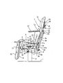
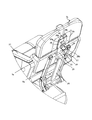
図1〜図3において、1は床面に固定された台座、2は台座1の中央位置に立設された支持柱であって、この支持柱2の上端部に基台3が固設されており、この基台3の前後方向の中央部付近に位置して、座部取付板4が軸支板5とピン5bによって上下方向回動自在に軸支されている。座部取付板4の上面には、バネやクッション等で構成された座部6が張り合わされている。
Hereinafter, an embodiment of a barber / beauty chair according to the present invention will be described with reference to the drawings.
In FIG. 1 to FIG. 3,
背凭れ7は、下部背凭れ7aと上部背凭れ7bに分割されている。下部背凭れ7aを取り付けられた左右一対の下部背凭れフレーム8aは、その下部先端部分がナギナタ状に外側へ反った形状とされており、下端部寄りの位置に設けられたピン10によって前後方向に回動自在とされていると共に、先端位置においてピン9によってエアシリンダ11の一方の端部に回動自在に連結されている。エアシリンダ11の他方の端部であるピストンロッド12は、基台3の前端部下面に固設されているロッド取付板13にピン14によって回動自在に連結されている。
The
また、前記下部背凭れフレーム8先端のピン9には、リンク32の一方の端部が回動自在に軸支され、該リンク32の他端はピン15と取付板16によって基台3の後端下面に回動自在に連結されている。さらに、前記ピン9には、前垂れ昇降用ロッド17の一方の端部が回動自在に取り付けられていると共に、この前垂れ昇降用ロッド17の他方の端部はピン18(図3参照)によって前垂れ取付板19に回動自在に連結されている。前垂れ取付板19の外面には、バネやクッション等で構成された前垂れ20が張り合わされている。
One end of a
前記前垂れ20を張り合わされた前垂れ取付板19は、連結ピン20aによって座部取付板4の先端部に回動自在に連結されており、前垂れ昇降用ロッド17で前方へ押されることにより、図1の状態から図3の状態まで押し上げられ、着座している被施術者の脚部を持ち上げるものである。
The front
また、下部背凭れフレーム8aの内側位置には、への字状をしたリンク21がピン10に対して回動自在に軸支されている。この回動自在なへの字状をしたリンク21の一方の突出片部21aは座部取付板4の下面に固設されていると共に、他方の突出片部21bは下部背凭れフレーム8aの外側まで達する長さに形成され、斜め下方に向けて突出配置されている。そして、このへの字状をした左右一対のリンク21の突出片部21bの先端部間には、回動ロッド22が回動自在に掛け渡されている(図3参照)。
Further, a U-shaped
一方、下部背凭れフレーム8aの上端部には、回動ロッド23が左右一対の下部背凭れフレーム8a間にわたって回動自在に掛け渡されている(図3参照)。この回動ロッド23の中央位置には、左右一対のリンク24が外側斜め下方に向けて回動ロッド23に溶接等で固設され、回動ロッド22と一体となって回動するように構成されている。さらに、この左右一対のリンク24の先端部間には、第2の回動ロッド25が回動自在に掛け渡されている。
On the other hand, on the upper end of the
前記第2の回動ロッド25と、下部背凭れフレーム8aの下部側の回動ロッド22には、長板状のリンク板26が掛け渡され、リンク板26の上下両端部は溶接等によって回動ロッド25と22に一体に連結されている。このリンク板26による連結によって、下側のへの字状をしたリンク21が回動したときにリンク板25を介して上側のリンク24が一緒になって回動するようになる。すなわち、前記ピン(結節点)10、リンク21、回動ロッド(結節点)22、リンク板26、回動ロッド(結節点)25、リンク24、回動ロッド23(結節点)は、いわゆる四節平行リンク機構を形成している。
A long plate-
さらに、前記四節平行リンク機構を構成する回動ロッド23には、上部背凭れ連結板27が溶接等によって回動ロッド23と一体に固設されており、回動ロッド23の回動に従って上部背凭れ連結板27も一体になって回動するように構成されている。そして、この上部背凭れ連結板27に、上部背凭れ7bを取り付けることによって、上部背凭れ7bが連結板27と一体となって回動するように構成されている。
Furthermore, an upper
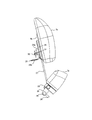
図4および図5に、前記上部背凭れ連結板27と上部背凭れ7bとの連結機構の詳細な構造を示す。
上部背凭れ7b裏面の上部背凭れ取付板8bには、連結板挿通部28が設けられている。この連結板挿通部28には、前記上部背凭れ連結板27と同一断面形状で、かつ、その寸法がわずかに大きくされた連結板挿通穴28aが形成されている。上部背凭れ連結板27をこの連結板挿通穴28aに挿通することにより、下部背凭れ7aと上部背凭れ7bとが連結されている。
4 and 5 show the detailed structure of the connecting mechanism between the upper
A connecting
連結板挿通部28には、上部背凭れ7bの上下方向の位置を調節するための位置調整機構も備えている。すなわち、連結板挿通部28の上面に位置して、てこ状をしたストッパー29がビス30によって取り付けられており、このビス30とストッパー29との間にバネ31が縮設され、このバネの伸張力によってストッパー先端のロック片29aを常に連結板挿通部28の上面に押しつけている。そして、連結板挿通部28の上面には、前記ストッパー29先端のロック片29aが入り込む大きさの窓28bが開けられていると共に、連結板挿通穴28a内に挿通されている上部背凭れ取付板27にも同じ大きさの窓(図示なし)が所定の位置に形成されている。
The connecting
したがって、内部に挿通されている上部背凭れ取付板27の窓を連結板挿通部28の窓28bの位置に合わせると、ストッパー先端のロック片29aがバネ31の力によって連結板挿通部28の窓28aから内部の上部背凭れ取付板27の窓に入り込み、上部背凭れ7bを該位置にロックする。これによって、上部背凭れ7bは、定位置に固定される。
Accordingly, when the window of the upper
一方、ストッパー29の取っ手部29bを下側に向けて押すと、バネ31に抗してストッパー先端のロック片29aが持ち上がり、係合していた窓28bから外れるので、この状態で上部背凭れ7bを下側に向けて押し込めば、上部背凭れ7bを上部背凭れ取付板27の細幅の穴39の下端に当たる位置まで押し下げることができる。
On the other hand, when the
なお、上部背凭れ取付板27に窓を複数個形成しておけば、上部背凭れ7bの位置を複数段にわたって調整することができる。また、上部背凭れ取付板27の中央部に縦方向に穿たれた細幅の穴39は、上部背凭れ7bの上下方向の調節範囲を制限するための穴である。また、ストッパー29を取り付けるためのネジ30のネジ先端部の接触をさけるための逃げ穴である。
If a plurality of windows are formed on the upper
33は座部6の左右側部に設けられたシリンダロック解除レバーであって、ピン34を支点として回動可能とされており、該レバーの下部先端に取り付けられた連結杆35によってピストンロッド12先端のロック解除ユニット36につながれている。
37は座部6の両サイドに取り付けられた肘掛け、38は座部の昇降を操作するための座部昇降用足踏みバーであって、バー38を足で踏んで操作することにより支持柱2の先端に取り付けられた基台3を上下方向に昇降させ、座部6の上下方向の位置を調整するものである。
37 is an armrest attached to both sides of the
次に、背凭れ7を図1の起立状態から図3の安楽姿勢の状態まで傾倒させる場合の動作について説明する。
まず最初に、被施術者が座部6に座ったら、上部背凭れ7bの裏面側に設けられている前述した位置調整機構のストッパー29を操作して、上部背凭れ7bが着座している被施術者の肩部に当たるようにその位置を上下方向に調整する。
Next, the operation when the
First, when the person to be treated is seated on the
次いで、シリンダロック解除レバー33を操作してエアシリンダ11のロックを解除する。このロック解除状態において、着座している被施術者が背凭れ7に体重をかけていくと、背凭れ7は下部背凭れフレーム8aのピン10を支点として時計方向(後方)へ回動していく。
Next, the cylinder
下部背凭れフレーム8aがピン10を支点として時計方向へ回動していくと、下部背凭れフレーム8aの下部先端のピン9に連結されたエアシリンダ11を押し縮めながら、その緩衝作用によってゆっくりと前方側へ向かって回動していく。これによって、同じくピン9に連結された前垂れ昇降用ロッド17も前方へ向かって押し出されていき、前垂れ20を上方へ向けて押し上げていく。同時に、座部6が基台3の中央部付近に設けられた軸支板5のピン5bを回動支点として時計回りに回動され、座部6の後端部が下がっていく。
When the
一方、上記のようにして下部背凭れフレーム8aが時計方向に回動していくと、への字状をしたリンク21の突出片部21bと下部背凭れフレーム8aとの交差角度が図3に示すように大きくなっていき、四節平行リンク作用によってリンク21の突出片部21bが徐々に下部背凭れフレーム8aに対して立ち上がった状態となっていく。この結果、四節平行リンク機構を構成するリンク板26が上方の回動ロッド25を押し上げていき、該回動ロッド25に連結された回動リンク24を上方へ向けて回動し、この回動リンク24を固設された回動ロッド23が半時計方向(図1において)に回転する。
On the other hand, when the
回動ロッド23が半時計方向へ回転されていくと、この回動ロッド23に固設された上部背凭れ取付板27が前方側へ向かって回動し、この上部背凭れ取付板27に取り付けられた上部背凭れ7bも前方側へ向かって回動され、上部背凭れ7bは常に図1の起立状態と同じ向きに保持される。
When the
着座した被施術者の体重によってさらに下部背凭れフレーム8aが後方へ向かって回動すると、これに伴って前垂れ昇降ロッド17が前垂れ20を所定の角度位置まで押し上げると共に、座部6の後端を図3のように所定の位置まで押し下げていき、座部6をチルトする。
When the
このようにして、エアシリンダ11のピストンロッド12が図3のように最大縮退位置まで縮むと、下部背凭れフレーム8aはそれ以上回動することが不可能となり、図3の安楽姿勢の位置に停止される。この結果、前垂れ20は図1から図3の状態まで持ち上げられ、また座部6は図1の水平な状態から図3の座部後端が下がったチルト状態となる。さらに、上部背凭れ7bは下部背凭れフレームの背面部分に形成された四節平行リンク機構によって、図3に示すように、図1と同じ向きの起立状態に保持される。
In this way, when the
上記のようにして、実施の形態に係る理美容用椅子によれば、背凭れを傾倒したにもかかわらず、着座している被施術者の顔を常に正面(鏡の方向)に向け続けることができる。また、着座時に上部背凭れを被施術者の座高に応じた最適高さに調節できるので、上部背凭れによって背中の肩胛骨付近を安定的に保持することができ、無理のない安楽な姿勢をとらせることができる。さらに、背凭れが倒れるのに連動して座面がチルトされるので、尻の位置が前方へずれることを防止することができる。 As described above, according to the barber / beauty chair according to the embodiment, the face of the sitting patient always keeps facing the front (the direction of the mirror) even though the backrest is tilted. Can do. In addition, the upper backrest can be adjusted to the optimal height according to the sitting height of the patient when seated, so that the upper backrest can stably hold the area around the shoulder ribs of the back and take a comfortable and comfortable posture. Can be made. Furthermore, since the seating surface is tilted in conjunction with the fall of the backrest, it is possible to prevent the position of the buttocks from shifting forward.
図3の安楽姿勢から図1の起立状態にもどすには、シリンダロック解除レバー33を操作して、エアシリンダ11のピストンロッド12を図1の状態まで押し出していけばよい。これによって、すべての部材が前述した図1から図3へ姿勢を変えるときと逆の動きをし、図1の起立状態に復帰させることができる。
To return to the standing position of FIG. 1 from the comfortable posture of FIG. 3, the cylinder
なお、上記実施の形態では、背凭れ傾倒時の傾倒速度を制御するための緩衝機構としてエアシリンダ11を用いたが、これに限らず、油圧シリンダ、ばねシリンダ、ねじシリンダ等の他の緩衝機構や部材を用いてもよいものである。また、下部背凭れフレーム8a下端のピン9と基台3との間にリンク32を設けたが、このリンク32は座部6と背凭れ7の角度を一意的に決定するリンクである。
In the above embodiment, the
1 台座
2 支持柱
3 基台
4 座部取付板
5 軸支板
5b ピン
6 座部
7 背凭れ
7a 下部背凭れ
7b 上部背凭れ
8a 下部背凭れフレーム
8b 上部背凭れフレーム
9 ピン
10 ピン
11 エアシリンダ
12 ピストンロッド
13 ロッド取付板
14 ピン
15 ピン
16 取付板
17 前垂れ昇降用ロッド
18 ピン
19 前垂れ取付板
20 前垂れ
21 リンク
21a 突出片部
21b 突出片部
22 回動ロッド
23 回動ロッド
24 回動リンク
25 回動ロッド
26 リンク板
27 上部背凭れ取付板
28 連結板挿通部
28a 連結板挿通穴
28b 窓
29 ストッパー
29a ロック片
30 ビス
31 バネ
32 リンク
33 シリンダロック解除機構
34 ピン
35 連結杆
36 ロック解除ユニット
37 肘掛け
38 座部昇降用足踏みレバー
39 穴
DESCRIPTION OF
Claims (3)
前記背凭れを下部背凭れと上部背凭れとに二分割し、
下部背凭れを取り付けられた下部背凭れフレームを下部寄り所望位置の回動支点を中心として前後方向に回動自在に支承すると共に、下部背凭れの背面側に、前記下部背凭れフレームの上端部と前記回動支点間を一辺とする四節平行リンク機構を形成し、
前記下部背凭れフレームが前記回動支点を中心として後方へ傾倒されたときに前記四節平行リンク機構の上部側結節点が上方へ向かって回動するようになし、
該上方へ向かって回動する結節点に上部背凭れ取付板を固設すると共に、該回動する上部背凭れ取付板に上部背凭れを取り付けたこと
を特徴とする理美容用椅子。 A reclining hairdressing and beauty chair with a seat, front sag and backrest,
Dividing the back into two parts, a lower back and an upper back,
The lower back frame, to which the lower back frame is attached, is supported so as to be pivotable in the front-rear direction around the pivot point at the desired position near the lower side, and the upper end portion of the lower back frame is mounted on the back side of the lower back frame. And a four-bar parallel link mechanism with one side between the pivot points,
When the lower backrest frame is tilted backward about the rotation fulcrum, the upper node of the four-bar parallel link mechanism is rotated upward,
A hairdressing and beauty chair characterized in that an upper backrest mounting plate is fixed to a node that pivots upward, and an upper backrest is mounted on the pivoting upper backrest mounting plate.
座部がその前後方向ほぼ中央位置において前後方向に揺動可能に支承され、該揺動可能とされた座部の先端に前垂れが回動自在に連結されていると共に、前記前垂れと前記下部背凭れフレームの下部先端との間には前垂れ昇降用ロッドが連結され、
前記下部背凭れフレームが後方へ傾倒されたときに、前記前垂れ昇降用ロッドが前進して前垂れを上方へ押し上げると共に、傾倒する下部背凭れフレームが前記座部をその揺動支点を中心として後方へ向けて押し下げ、チルトするようにしたこと
を特徴とする理美容用椅子。 The barber / beauty chair according to claim 1,
The seat portion is supported so as to be swingable in the front-rear direction at a substantially central position in the front-rear direction, and a front suspension is rotatably connected to a tip of the swingable seat portion, and the front suspension and the lower back are connected to each other. A rod for raising and lowering the front is connected between the lower end of the drowning frame,
When the lower backrest frame is tilted backward, the forward / lowering rod moves forward to push the forward suspension upward, and the tilted lower backrest frame moves the seat portion backward with the swinging fulcrum as a center. A hairdressing and beauty chair characterized by being pushed down and tilted.
前記上部背凭れ取付板と上部背凭れとの間に、上部背凭れの上下方向の位置を調整可能な位置調整機構を設けたことを特徴とする理美容用椅子。 In the barber / beauty chair according to claim 1 or 2,
A barber / beauty chair characterized in that a position adjustment mechanism capable of adjusting the vertical position of the upper backrest is provided between the upper backrest mounting plate and the upper backrest.
Priority Applications (1)
| Application Number | Priority Date | Filing Date | Title |
|---|---|---|---|
| JP2013079249A JP6112454B2 (en) | 2013-04-05 | 2013-04-05 | Barber chair |
Applications Claiming Priority (1)
| Application Number | Priority Date | Filing Date | Title |
|---|---|---|---|
| JP2013079249A JP6112454B2 (en) | 2013-04-05 | 2013-04-05 | Barber chair |
Publications (2)
| Publication Number | Publication Date |
|---|---|
| JP2014200475A true JP2014200475A (en) | 2014-10-27 |
| JP6112454B2 JP6112454B2 (en) | 2017-04-12 |
Family
ID=52351476
Family Applications (1)
| Application Number | Title | Priority Date | Filing Date |
|---|---|---|---|
| JP2013079249A Expired - Fee Related JP6112454B2 (en) | 2013-04-05 | 2013-04-05 | Barber chair |
Country Status (1)
| Country | Link |
|---|---|
| JP (1) | JP6112454B2 (en) |
Families Citing this family (1)
| Publication number | Priority date | Publication date | Assignee | Title |
|---|---|---|---|---|
| CN108323986B (en) * | 2018-02-10 | 2019-09-17 | 中山市思尚家具有限公司 | Chair |
Citations (6)
| Publication number | Priority date | Publication date | Assignee | Title |
|---|---|---|---|---|
| US2618313A (en) * | 1950-06-05 | 1952-11-18 | Fred J Piotraschke | Reclining chair |
| JPS62153935U (en) * | 1986-09-24 | 1987-09-30 | ||
| JPS63179845U (en) * | 1987-05-13 | 1988-11-21 | ||
| JP2003144263A (en) * | 2001-11-16 | 2003-05-20 | Takara Belmont Co Ltd | Relaxation chair |
| JP2004065952A (en) * | 2002-06-14 | 2004-03-04 | Takara Belmont Co Ltd | Chair backrest |
| JP2010124885A (en) * | 2008-11-25 | 2010-06-10 | Beautiful Life Co Ltd | Chair |
-
2013
- 2013-04-05 JP JP2013079249A patent/JP6112454B2/en not_active Expired - Fee Related
Patent Citations (6)
| Publication number | Priority date | Publication date | Assignee | Title |
|---|---|---|---|---|
| US2618313A (en) * | 1950-06-05 | 1952-11-18 | Fred J Piotraschke | Reclining chair |
| JPS62153935U (en) * | 1986-09-24 | 1987-09-30 | ||
| JPS63179845U (en) * | 1987-05-13 | 1988-11-21 | ||
| JP2003144263A (en) * | 2001-11-16 | 2003-05-20 | Takara Belmont Co Ltd | Relaxation chair |
| JP2004065952A (en) * | 2002-06-14 | 2004-03-04 | Takara Belmont Co Ltd | Chair backrest |
| JP2010124885A (en) * | 2008-11-25 | 2010-06-10 | Beautiful Life Co Ltd | Chair |
Also Published As
| Publication number | Publication date |
|---|---|
| JP6112454B2 (en) | 2017-04-12 |
Similar Documents
| Publication | Publication Date | Title |
|---|---|---|
| ES2399840T3 (en) | Joint mechanism for a recliner | |
| JP5634891B2 (en) | Chair | |
| JP6865477B2 (en) | Chair | |
| JP2009509592A (en) | Chair | |
| KR101715092B1 (en) | A Front height adjustable sliding folding chair | |
| CN102781281A (en) | Device for synchronizing the seat and backrest of a chair | |
| JP3547415B2 (en) | Reclining wheelchair | |
| CN105962667A (en) | Mechanical stretching device and chair unit | |
| US20120248835A1 (en) | Sofa lovers' sofa | |
| JP6112454B2 (en) | Barber chair | |
| JP5433312B2 (en) | Lifting reclining wheelchair | |
| JP2010162337A (en) | Chair | |
| KR101767170B1 (en) | Foldable bath chair | |
| JP2004065507A (en) | Chair for hairdressing | |
| CN203506076U (en) | Chair structure | |
| CN113208336A (en) | Seat surface inclination angle adjusting structure and leisure chair | |
| JP2010104562A (en) | Chair | |
| JP4753354B2 (en) | Hairdressing shampoo chair | |
| JPH0662935A (en) | Chair | |
| JP3183389U (en) | Reclining chair | |
| JP6423236B2 (en) | Knee-raised multifunction chair | |
| JPH11113967A (en) | Wheelchair | |
| CN215502076U (en) | Support driving mechanism | |
| JP3225237U (en) | Chair | |
| CN115299726B (en) | Chair is adjusted to seat station |
Legal Events
| Date | Code | Title | Description |
|---|---|---|---|
| A621 | Written request for application examination |
Free format text: JAPANESE INTERMEDIATE CODE: A621 Effective date: 20160126 |
|
| A521 | Request for written amendment filed |
Free format text: JAPANESE INTERMEDIATE CODE: A523 Effective date: 20160302 |
|
| A977 | Report on retrieval |
Free format text: JAPANESE INTERMEDIATE CODE: A971007 Effective date: 20161226 |
|
| A131 | Notification of reasons for refusal |
Free format text: JAPANESE INTERMEDIATE CODE: A131 Effective date: 20170110 |
|
| A521 | Request for written amendment filed |
Free format text: JAPANESE INTERMEDIATE CODE: A523 Effective date: 20170116 |
|
| A131 | Notification of reasons for refusal |
Free format text: JAPANESE INTERMEDIATE CODE: A131 Effective date: 20170131 |
|
| A521 | Request for written amendment filed |
Free format text: JAPANESE INTERMEDIATE CODE: A523 Effective date: 20170201 |
|
| TRDD | Decision of grant or rejection written | ||
| A01 | Written decision to grant a patent or to grant a registration (utility model) |
Free format text: JAPANESE INTERMEDIATE CODE: A01 Effective date: 20170214 |
|
| A61 | First payment of annual fees (during grant procedure) |
Free format text: JAPANESE INTERMEDIATE CODE: A61 Effective date: 20170303 |
|
| R150 | Certificate of patent or registration of utility model |
Ref document number: 6112454 Country of ref document: JP Free format text: JAPANESE INTERMEDIATE CODE: R150 |
|
| R250 | Receipt of annual fees |
Free format text: JAPANESE INTERMEDIATE CODE: R250 |
|
| R250 | Receipt of annual fees |
Free format text: JAPANESE INTERMEDIATE CODE: R250 |
|
| R250 | Receipt of annual fees |
Free format text: JAPANESE INTERMEDIATE CODE: R250 |
|
| R250 | Receipt of annual fees |
Free format text: JAPANESE INTERMEDIATE CODE: R250 |
|
| LAPS | Cancellation because of no payment of annual fees |