JP2014200480A - Game machine - Google Patents
Game machine Download PDFInfo
- Publication number
- JP2014200480A JP2014200480A JP2013079382A JP2013079382A JP2014200480A JP 2014200480 A JP2014200480 A JP 2014200480A JP 2013079382 A JP2013079382 A JP 2013079382A JP 2013079382 A JP2013079382 A JP 2013079382A JP 2014200480 A JP2014200480 A JP 2014200480A
- Authority
- JP
- Japan
- Prior art keywords
- effect
- piston
- air
- symbol
- blowing
- Prior art date
- Legal status (The legal status is an assumption and is not a legal conclusion. Google has not performed a legal analysis and makes no representation as to the accuracy of the status listed.)
- Granted
Links
- 230000000694 effects Effects 0.000 claims abstract description 315
- 238000007664 blowing Methods 0.000 claims abstract description 69
- 230000007246 mechanism Effects 0.000 claims abstract description 18
- 238000003860 storage Methods 0.000 description 17
- 230000008859 change Effects 0.000 description 15
- 238000004519 manufacturing process Methods 0.000 description 15
- 238000009826 distribution Methods 0.000 description 11
- 230000006870 function Effects 0.000 description 5
- 230000005236 sound signal Effects 0.000 description 5
- 239000002184 metal Substances 0.000 description 4
- 238000000034 method Methods 0.000 description 4
- 230000008569 process Effects 0.000 description 4
- 239000011347 resin Substances 0.000 description 4
- 229920005989 resin Polymers 0.000 description 4
- 101100168642 Arabidopsis thaliana CRN gene Proteins 0.000 description 3
- 101100045632 Arabidopsis thaliana TCX2 gene Proteins 0.000 description 3
- 101100045633 Arabidopsis thaliana TCX3 gene Proteins 0.000 description 3
- 101150037491 SOL1 gene Proteins 0.000 description 3
- 230000009471 action Effects 0.000 description 3
- 239000000463 material Substances 0.000 description 3
- 101150103732 sol2 gene Proteins 0.000 description 3
- 238000009423 ventilation Methods 0.000 description 3
- 238000001125 extrusion Methods 0.000 description 2
- 239000004925 Acrylic resin Substances 0.000 description 1
- 229920000178 Acrylic resin Polymers 0.000 description 1
- 230000004913 activation Effects 0.000 description 1
- 230000004397 blinking Effects 0.000 description 1
- 238000010586 diagram Methods 0.000 description 1
- 238000005401 electroluminescence Methods 0.000 description 1
- 239000011521 glass Substances 0.000 description 1
- 238000001746 injection moulding Methods 0.000 description 1
- 238000009434 installation Methods 0.000 description 1
- 230000001795 light effect Effects 0.000 description 1
- 238000012538 light obscuration Methods 0.000 description 1
- 239000004973 liquid crystal related substance Substances 0.000 description 1
- 239000011159 matrix material Substances 0.000 description 1
- 230000002093 peripheral effect Effects 0.000 description 1
- 238000007747 plating Methods 0.000 description 1
- 239000011120 plywood Substances 0.000 description 1
- 238000004904 shortening Methods 0.000 description 1
- 239000000758 substrate Substances 0.000 description 1
- 238000004381 surface treatment Methods 0.000 description 1
- 230000001960 triggered effect Effects 0.000 description 1
Images


Landscapes
- Pinball Game Machines (AREA)
- Display Devices Of Pinball Game Machines (AREA)
Abstract
【課題】送風手段から空気を素早く送ることにより、遊技者に強いインパクトを与えることが可能な遊技機を提供すること。
【解決手段】本発明の遊技機は、空気を送る送風手段120と、送風手段120を作動させる送風演出を実行させる制御を行う送風演出実行制御手段とを備える。送風手段120は、ピストン機構121及び保持手段123を備える。ピストン機構121は、シリンダ本体122、回転軸125を有するモータ123、及び、回転軸125に連結され、第1位置と第2位置との間でシリンダ本体122内を往復動することにより、シリンダ本体122外に空気を押し出すピストン124からなる。保持手段123は、第1位置でピストン124を保持しておく機能を有する。
【選択図】図5To provide a gaming machine capable of giving a strong impact to a player by quickly sending air from a blowing means.
A gaming machine according to the present invention includes a blowing means 120 for sending air and a blowing effect execution control means for performing a control for executing a blowing effect for operating the blowing means 120. The air blowing unit 120 includes a piston mechanism 121 and a holding unit 123. The piston mechanism 121 is connected to the cylinder main body 122, the motor 123 having the rotation shaft 125, and the rotation shaft 125, and reciprocates between the first position and the second position in the cylinder main body 122. The piston 124 pushes air out 122. The holding means 123 has a function of holding the piston 124 at the first position.
[Selection] Figure 5
Description
本発明は、空気を送る送風手段を備える遊技機に関するものである。 The present invention relates to a gaming machine provided with air blowing means for sending air.
従来より、特定の遊技状態が発生したことを遊技者に報知するために、遊技機の枠部材や操作ハンドルなどから遊技者に向けて空気を送る送風手段を備えた遊技機が提案されている(例えば特許文献1,2参照)。このような遊技機では、送風手段から噴出した空気の圧力を感じ取らせることにより、遊技者に特定の遊技状態の発生を認識させることができる。 Conventionally, in order to notify a player that a specific gaming state has occurred, a gaming machine provided with a blowing means for sending air toward the player from a frame member or an operation handle of the gaming machine has been proposed. (For example, refer to Patent Documents 1 and 2). In such a gaming machine, it is possible to make the player recognize the occurrence of a specific gaming state by feeling the pressure of the air ejected from the blowing means.
ところが、特許文献1に記載の遊技機は、送風手段がファン式であるため、送風手段が作動し始めてから空気が噴出されるまでに時間が掛かってしまう。また、特許文献2に記載の遊技機についても、送風手段がエアポンプ式であり、内部の空気圧が高まるまでに時間が掛かるため、送風手段が作動し始めてから空気が噴出されるまでに時間が掛かってしまう。従って、遊技者は、送風手段が作動した時点で空気の噴出を予測できてしまうため、空気を送ったとしても、強いインパクトを与えることができないという問題がある。 However, in the gaming machine described in Patent Document 1, since the air blowing means is a fan type, it takes time until air is ejected after the air blowing means starts operating. Also, in the gaming machine described in Patent Document 2, since the air blowing means is an air pump type and it takes time until the internal air pressure increases, it takes time from the start of the air blowing means until the air is ejected. End up. Therefore, since the player can predict the ejection of air when the air blowing means is activated, there is a problem that even if air is sent, a strong impact cannot be given.
本発明は上記の課題に鑑みてなされたものであり、その目的は、送風手段から空気を素早く送ることにより、遊技者に強いインパクトを与えることが可能な遊技機を提供することにある。 The present invention has been made in view of the above problems, and an object of the present invention is to provide a gaming machine capable of giving a strong impact to a player by quickly sending air from a blowing means.
上記の課題を解決するために、請求項1に記載の発明は、空気を送る送風手段と、前記送風手段を作動させる送風演出を実行させる制御を行う送風演出実行制御手段とを備えた遊技機であって、前記送風手段は、シリンダ本体、回転軸を有するモータ、及び、前記回転軸に連結され、第1位置と第2位置との間で前記シリンダ本体内を往復動することにより、前記シリンダ本体外に空気を押し出すピストンからなるピストン機構と、前記第1位置で前記ピストンを保持しておく保持手段とを備えることを特徴とする遊技機をその要旨とする。 In order to solve the above-mentioned problem, the invention described in claim 1 is a gaming machine comprising a blowing means for sending air and a blowing effect execution control means for performing a control for executing a blowing effect for operating the blowing means. The air blowing means is connected to the cylinder body, a motor having a rotation shaft, and the rotation shaft, and reciprocates in the cylinder body between a first position and a second position. The gist of the gaming machine is characterized by comprising a piston mechanism comprising a piston for pushing air out of the cylinder body and holding means for holding the piston in the first position.
従って、請求項1に記載の発明によると、モータの回転軸の回転をピストンの運動に変換し、ピストンの往復動によってシリンダ本体外に空気を押し出す構造であるため、モータの回転速度を調整することにより、シリンダ本体外に空気を素早く押し出すことができる。その結果、送風手段から空気を素早く送ることができるため、遊技者は、送風手段が作動するとほぼ同時に空気の噴出に気付くようになる。この場合、遊技者は、空気の噴出を事前に予測できないため、遊技者に強いインパクトを与えることが可能になる。 Therefore, according to the first aspect of the invention, the rotation speed of the motor is adjusted because the rotation of the rotation shaft of the motor is converted into the movement of the piston and the air is pushed out of the cylinder body by the reciprocation of the piston. Thus, air can be quickly pushed out of the cylinder body. As a result, air can be quickly sent from the blowing means, so that the player becomes aware of the ejection of air almost simultaneously with the operation of the blowing means. In this case, since the player cannot predict the ejection of air in advance, it is possible to give a strong impact to the player.
しかも、送風手段は、第1位置でピストンを保持する保持手段を備えているため、保持手段による保持を解除してピストン機構を駆動すると、すぐにシリンダ本体内の空気が押し出されるようになる。ゆえに、モータの駆動音によって、空気の噴出が遊技者に事前に予測されてしまうといった事態をより確実に防止することができる。しかも、第1位置が、シリンダ本体内の容積が最大となる位置である場合には、モータの駆動開始時に第1位置からピストンを駆動すると、送風手段からは大量の空気が送られるようになる。その結果、遊技者は、空気の噴出に気付きやすくなるため、遊技者により強いインパクトを与えることができる。また、送風手段は、モータの回転軸を回転させるだけで、ピストンが往復動して空気が押し出される構造を有しているため、空気を連続発射する際に有利である。 In addition, since the air blowing means includes a holding means for holding the piston in the first position, when the piston mechanism is driven by releasing the holding by the holding means, the air in the cylinder body is immediately pushed out. Therefore, it is possible to more reliably prevent a situation in which air blow-out is predicted in advance by the player due to the driving sound of the motor. In addition, when the first position is a position where the volume in the cylinder body is maximized, when the piston is driven from the first position at the start of driving the motor, a large amount of air is sent from the blower means. . As a result, the player can easily be aware of the air ejection, so that the player can have a stronger impact. Further, since the air blowing means has a structure in which the piston is reciprocated and the air is pushed out only by rotating the rotating shaft of the motor, it is advantageous when air is continuously emitted.
さらに、保持手段としては特に限定されないが、例えば、シリンダ本体、モータ及びピストンからなるピストン機構とは別体に設けられ、第1位置でピストンに係合するロックピンなどを挙げることができる。また、他の保持手段としては、ピストン機構と一体に設けられ、第1位置でピストンを停止させるモータなどを挙げることができる。この場合、保持手段として用いられるモータは、ピストン機構を構成するモータと同じものである。 Furthermore, the holding means is not particularly limited, and examples thereof include a lock pin that is provided separately from a piston mechanism including a cylinder body, a motor, and a piston and that engages with the piston at the first position. Other holding means may include a motor that is provided integrally with the piston mechanism and stops the piston at the first position. In this case, the motor used as the holding means is the same as the motor constituting the piston mechanism.
請求項2に記載の発明は、請求項1において、前記ピストン機構は、前記回転軸に連結されたピニオンギヤと、前記ピストンの裏側から突出し、前記ピニオンギヤに噛み合うラックギヤと、前記第1位置から前記第2位置に向けて前記ピストンを付勢する付勢部材とを備えることをその要旨とする。 According to a second aspect of the present invention, in the first aspect, the piston mechanism includes a pinion gear coupled to the rotating shaft, a rack gear protruding from the back side of the piston and meshing with the pinion gear, and the first position from the first position. The gist is to include a biasing member that biases the piston toward the second position.
従って、請求項2に記載の発明によると、モータの回転軸の回転をピストンの運動に変換し、バネ等の付勢部材の付勢力によってピストンを第2位置に移動させることにより、シリンダ本体外に空気を押し出す構造である。このため、モータの回転速度を調整することにより、モータの駆動力と付勢部材の付勢力とによって、シリンダ本体外に空気をより素早く押し出すことができる。その結果、送風手段から空気をより素早く送ることができるため、遊技者は、空気の噴出をより確実に予測できなくなり、遊技者により強いインパクトを与えることが可能になる。 Therefore, according to the second aspect of the present invention, the rotation of the rotating shaft of the motor is converted into the movement of the piston, and the piston is moved to the second position by the biasing force of the biasing member such as a spring. It is a structure that pushes out air. For this reason, by adjusting the rotational speed of the motor, air can be pushed out of the cylinder body more quickly by the driving force of the motor and the urging force of the urging member. As a result, since air can be sent more quickly from the blowing means, the player cannot predict the ejection of air more reliably, and can have a stronger impact on the player.
請求項3に記載の発明は、請求項1または2において、前記送風手段は、前記シリンダ本体の内外を連通させる送風口と、基端部が前記送風口に接続され、前記シリンダ本体内から押し出された空気を通過させる送風管と、前記送風管の先端部に接続され、前記送風管を通過した空気を噴出させる空気噴出口とからなる送風ユニットを備えることをその要旨とする。 According to a third aspect of the present invention, in the first or second aspect, the air blowing unit is configured to be connected to the inside and outside of the cylinder main body and a base end portion connected to the air blowing port, and pushed out from the cylinder main body. The gist of the present invention is to include a blower unit that includes a blower pipe that allows the air to pass through and an air outlet that is connected to the tip of the blower pipe and ejects the air that has passed through the blower pipe.
従って、請求項3に記載の発明によると、シリンダ本体内から押し出された空気を、確実に空気噴出口から噴出させることができる。よって、送風手段から空気を確実に送ることができるようになる。 Therefore, according to the third aspect of the present invention, the air pushed out from the cylinder body can be surely ejected from the air ejection port. Therefore, air can be reliably sent from the blowing means.
なお、送風管の長さは特に限定されないが、送風管を短くすれば、送風口(シリンダ本体)と空気噴出口との距離が短くなるため、シリンダ本体内から押し出された空気を空気噴出口から素早く噴出させることができる。一方、送風管を長くすれば、シリンダ本体を空気噴出口から離すことができるため、ピストン機構の配置の自由度が高くなる。 The length of the blower pipe is not particularly limited. However, if the blower pipe is shortened, the distance between the blower opening (cylinder main body) and the air jet outlet is shortened. Can be ejected quickly. On the other hand, if the air duct is lengthened, the cylinder body can be separated from the air outlet, so that the degree of freedom in arranging the piston mechanism is increased.
請求項4に記載の発明は、請求項1乃至3のいずれか1項において、図柄を変動させる図柄変動ゲーム中に実行される演出の種類を決定する演出決定手段を備え、前記送風演出実行制御手段は、前記演出決定手段によって決定された前記演出の種類に基づいて、前記送風演出を実行させる制御を行うものであり、前記演出決定手段によって決定された前記演出が特定演出である場合に、前記特定演出の開始前に、前記ピストンを前記第1位置で保持させる制御を行うことをその要旨とする。 Invention of Claim 4 is provided with the effect determination means which determines the kind of effect performed in the symbol fluctuation | variation game which fluctuates a symbol in any one of Claim 1 thru | or 3, and the said ventilation effect execution control The means performs control to execute the air blowing effect based on the type of the effect determined by the effect determining means, and when the effect determined by the effect determining means is a specific effect, The gist is to perform control to hold the piston in the first position before the start of the specific effect.
従って、請求項4に記載の発明によると、送風演出を実行する際には、第1位置でピストンが確実に保持されるため、モータを駆動するとすぐに空気が押し出されるようになる。ゆえに、モータの駆動によって、送風演出が遊技者に事前に予測されてしまうといった事態をより確実に防止することができる。 Therefore, according to the fourth aspect of the present invention, when the air blowing effect is executed, the piston is reliably held at the first position, so that the air is pushed out as soon as the motor is driven. Therefore, it is possible to more reliably prevent a situation in which the air blow effect is predicted by the player in advance by driving the motor.
なお、特定演出は、図柄変動ゲーム中に実行される複数種類の演出から選択される演出であって、遊技者にプラスのイメージを与える演出であることが好ましい。具体的に言うと、図柄変動ゲーム中に実行される演出としては、図柄変動ゲームの結果が大当りとなる場合に、図柄変動ゲーム中に実行される大当り演出、図柄変動ゲームの結果が大当りとなる可能性がある場合に、図柄変動ゲーム中に実行されるリーチ演出、図柄変動ゲームの結果が大当りとなる可能性がない場合に、図柄変動ゲーム中に実行されるハズレ演出などが挙げられる。そして、複数種類の演出から選択される特定演出の具体例としては、図柄変動ゲーム中に実行される大当り演出やリーチ演出を挙げることができる。 The specific effect is an effect selected from a plurality of types of effects executed during the symbol variation game, and is preferably an effect that gives a positive image to the player. Specifically, as the effects executed during the symbol variation game, when the result of the symbol variation game becomes a big hit, the big hit effect executed during the symbol variation game, the result of the symbol variation game becomes a big hit There is a reach effect executed during the symbol variation game when there is a possibility, and a lose effect performed during the symbol variation game when the result of the symbol variation game is not likely to be a big hit. And as a specific example of the specific effect selected from a plurality of types of effects, a jackpot effect and a reach effect that are executed during the symbol variation game can be mentioned.
請求項5に記載の発明は、請求項1乃至4のいずれか1項において、前記送風演出実行制御手段は、電源投入時に、前記ピストンを前記第1位置で保持させる制御を行うことをその要旨とする。 The gist of a fifth aspect of the present invention is that, in any one of the first to fourth aspects, the blowing effect execution control means performs control to hold the piston at the first position when power is turned on. And
例えば、送風演出の実行直前にピストンを第1位置で保持させるような制御であると、ピストンを第1位置に移動させる動作によって、送風演出が遊技者に予測されてしまう。そこで、請求項5では、電源投入時に、ピストンを第1位置で保持させるようにしている。従って、送風演出が遊技者に事前に予測されてしまうといった事態をよりいっそう確実に防止できる。 For example, if the control is such that the piston is held at the first position immediately before the execution of the blowing effect, the blowing effect is predicted by the player by the operation of moving the piston to the first position. Therefore, in claim 5, when the power is turned on, the piston is held at the first position. Therefore, it is possible to more reliably prevent a situation in which a fan effect is predicted in advance by the player.
請求項6に記載の発明は、請求項1乃至5のいずれか1項において、前記送風演出実行制御手段は、前記送風演出の終了時に、前記ピストンを前記第1位置で保持させる制御を行うことをその要旨とする。 A sixth aspect of the present invention provides the air blow effect execution control unit according to any one of the first to fifth aspects, wherein the blower effect execution control unit performs control to hold the piston at the first position at the end of the air flow effect. Is the gist.
従って、請求項6に記載の発明によると、送風演出の終了時にピストンを第1位置で保持させるため、次回の送風演出においても、送風手段から空気をより素早く送ることができる。 Therefore, according to the invention described in claim 6, since the piston is held at the first position at the end of the air blowing effect, air can be sent more quickly from the air blowing means also in the next air blowing effect.
以上詳述したように、請求項1〜6に記載の発明によれば、送風手段から空気を素早く送ることにより、遊技者に強いインパクトを与えることが可能な遊技機を提供することができる。特に、請求項4に記載の発明によれば、モータの駆動によって、送風演出が遊技者に事前に予測されてしまうといった事態をより確実に防止することができる。 As described in detail above, according to the first to sixth aspects of the present invention, it is possible to provide a gaming machine capable of giving a strong impact to the player by quickly sending air from the blowing means. In particular, according to the fourth aspect of the present invention, it is possible to more reliably prevent a situation in which a fan effect is predicted in advance by the player by driving the motor.
以下、本発明の遊技機をパチンコ機10に具体化した一実施形態を図面に基づき説明する。
Hereinafter, an embodiment in which a gaming machine of the present invention is embodied in a
(1)パチンコ機10全体の概略構成
図1には、パチンコ機10の機表側が略示されている。このパチンコ機10は機体の外郭をなす縦長方形状の外枠11を備えている。外枠11には、機体を構成する縦長方形状の中枠12が、開閉及び着脱自在に組み付けられている。また、中枠12の前面側には、前枠14が横開き可能で開閉可能に組み付けられている。前枠14は、中央部に窓口14aを有するとともに、窓口14aの下方に上球皿15が一体的に組み付けられた構造を有している。前枠14の裏面側には、機内部に配置された遊技盤13を透視保護するためのガラス(図示略)が組み付けられている。また、前枠14の前面には、上側枠ランプ16a、左側枠ランプ16b及び右側枠ランプ16cが設けられている。各枠ランプ16a〜16cは、図示しない発光体(本実施形態では発光ダイオード)を備えた発光手段であり、発光体にレンズ部材を覆い被せることによって構成されている。これらの枠ランプ16a〜16cでは、パチンコ機10の各種遊技の演出態様(大当り、リーチなど)に応じて点灯(点滅)・消灯などの発光演出が実行されるようになっている。
(1) Schematic configuration of the
さらに、図1に示されるように、前枠14の下部には、下球皿18が一体的に組み付けられている。下球皿18の右方には、打球発射装置(図示略)を構成する操作ハンドル19が装着されている。そして、遊技者が操作ハンドル19を回動操作すると、上球皿15に貯留された遊技球は、打球発射装置によって発射されて遊技盤13の遊技盤面13a(図2参照)上に導かれるようになる。なお、本実施形態では、前枠14の下部に下球皿18及び操作ハンドル19が一体的に組み付けられているが、下球皿18及び操作ハンドル19を中枠12の前面側において前枠14の下方に組み付けるようにしてもよい。
Further, as shown in FIG. 1, a
(2)遊技盤13の構成
図2に示される遊技盤13は、ベニヤ板などの木製基板の表面に樹脂製のセルを貼付することによって略矩形板状に形成されている。なお、遊技盤13は、アクリル樹脂などの樹脂材料の射出成形によって略矩形板状に形成されたものであってもよい。遊技盤13の遊技盤面13aには、遊技球が流下可能な遊技領域32を区画する内レール33a及び外レール33bが略円形状に敷設されている。内レール33aと外レール33bとの間に生じる発射経路には、操作ハンドル19を操作した際に発射された遊技球が通過するようになっている。そして、打球発射装置によって発射されて発射経路を通過した遊技球は、発射経路の終端部から遊技領域32に進入し、遊技領域32内を流下するようになっている。また、遊技領域32内には風車34が配設され、遊技領域32の略全域には複数の遊技釘35が植設されている。風車34及び遊技釘35は、遊技領域32内を流下する遊技球の方向を変更するようになっている。
(2) Configuration of
図2に示されるように、遊技盤面13aの略中央部には、開口部50aを有する枠状のセンター役物50が装着されている。なお、遊技盤13の裏側には、図柄表示装置60が着脱自在に取り付けられている。図柄表示装置60の表示画面は、センター役物50の開口部50aを介して遊技盤13の前面側から視認可能となっている。なお、本実施形態の図柄表示装置60は液晶式であるが、ドットマトリクス式、エレクトロルミネッセンス素子式、7セグメント式の図柄表示装置であってもよい。また、図柄表示装置60では、変動表示(または画像表示)に基づく遊技演出(表示演出)が行われるようになっている。そして、図柄表示装置60では、表示演出に関連して、複数種類の演出図柄を3列で変動させる演出図柄変動ゲームが表示されるようになっている。なお、演出図柄は「0」〜「9」の10通りの数字を示す図柄である。
As shown in FIG. 2, a frame-shaped
図2に示されるように、遊技盤面13a上におけるセンター役物50の下方位置には、遊技盤面13a上を流下する遊技球が入賞可能な始動入賞装置51が配設されている。始動入賞口51aには、始動入賞口51aが形成されるとともに、一対の羽根部材51bからなる普通電動役物が一体的に構成されている。一対の羽根部材51bは、普通電動役物ソレノイドSOL1(図6参照)の励磁作用により開閉するようになっている。また、始動入賞装置51の奥方には、始動入賞口51aに入賞した遊技球を検知する始動口スイッチSE1(図2,図6参照)が設けられている。始動口スイッチSE1は、始動入賞装置51に入賞した遊技球を検知したことを契機として、オン状態となり、入賞信号を出力するようになっている。一方、始動口スイッチSE1は、遊技球を検知していないときにオフ状態となり、入賞信号を出力しなくなる。なお、入賞信号が出力された場合には、後述する特別図柄表示装置61による特別図柄変動ゲームが行われるとともに、図柄表示装置60による演出図柄変動ゲームが行われるようになっている。
As shown in FIG. 2, a
図2に示されるように、遊技盤面13a上における始動入賞装置51の下方には、遊技盤面13a上を流下する遊技球が入賞可能な大入賞装置52が配設されている。大入賞装置52の奥方には、入賞した遊技球を検知するカウントスイッチSE2(図2,図6参照)が設けられている。また、大入賞装置52の大入賞口扉52aは、大入賞口ソレノイドSOL2(図6参照)の励磁作用により、遊技球を受け入れない閉鎖状態、及び、遊技球を受け入れやすい開放状態に切替可能になっている。本実施形態において、大入賞口扉52aの「閉鎖状態」とは、大入賞口扉52aが完全に閉じている状態をいい、大入賞口扉52aの「開放状態」とは、大入賞口扉52aが完全に開いた状態をいう。なお、カウントスイッチSE2にて遊技球が検知された場合には、所定数(本実施形態では15個)の賞球の払い出しが行われるようになっている。
As shown in FIG. 2, a
また、センター役物50の左側には、遊技球の通過を検知する機能を有するゲート53が設けられている。ゲート53の奥方には、通過した遊技球を検知するゲートスイッチSE3(図2,図6参照)が設けられている。なお、ゲートスイッチSE3にて遊技球が検知された場合に乱数を取得し、取得した乱数が所定の乱数値であるか否かを判定した結果に基づいて普通電動役物ソレノイドSOL1が駆動される。このような判定(当り判定)によって普通電動役物の一対の羽根部材51bが開放されるため、始動入賞口51aに遊技球が入賞しやすくなる。
Further, a
図2に示されるように、センター役物50の右下方には、可視表示部を備えた特別図柄表示装置61が配設されている。特別図柄表示装置61では、始動入賞装置51への遊技球の入賞を契機として、複数種類の特別図柄(本実施形態では、「0」〜「9」の10種類の図柄)を変動させる特別図柄変動ゲームが表示され、該特別図柄変動ゲームの結果として、大当り及びハズレの表示結果が表示されるようになっている。例えば、特別図柄変動ゲームの結果が大当りとなる場合、特別図柄変動ゲームの終了時に、特別図柄として「0」〜「9」の10通りの数字を示す図柄が表示される。一方、特別図柄変動ゲームの結果がハズレとなる場合、特別図柄変動ゲームの終了時に、特別図柄としてハズレを示す「−」の図柄が表示される。
As shown in FIG. 2, a special
ここで、大当りとなる場合に表示される特別図柄は、確変図柄及び非確変図柄からなっている。確変図柄は、特別図柄変動ゲームにおいて大当りが導出される確率が高確率となる確率変動状態を開始させる契機となる図柄である。非確変図柄は、確率変動状態を開始させる契機とはならない通常状態となる図柄である。本実施形態の確変図柄は、「1」,「3」,「5」,「7」,「9」の数字を示す特別図柄である。一方、本実施形態の非確変図柄は、「0」,「2」,「4」,「6」,「8」の数字を示す特別図柄である。 Here, the special symbol displayed in the case of a big hit consists of a probability variation symbol and a non-probability variation symbol. The probability variation symbol is a symbol that triggers the start of a probability variation state in which the probability that a jackpot is derived in the special symbol variation game is high. The non-probable variation symbol is a symbol that is in a normal state that does not trigger the probability variation state. The probability variation symbol of this embodiment is a special symbol indicating the numbers “1”, “3”, “5”, “7”, “9”. On the other hand, the non-probable variation symbol of this embodiment is a special symbol indicating the numbers “0”, “2”, “4”, “6”, “8”.
さらに、本実施形態では、特別図柄表示装置61での特別図柄変動ゲームに合わせて、図柄表示装置60による演出図柄変動ゲームが行われる。具体的には、特別図柄変動ゲームの開始とほぼ同時に演出図柄変動ゲームが開始され、特別図柄変動ゲームの終了(大当りまたはハズレの表示結果が表示)とほぼ同時に演出図柄変動ゲームの結果が表示されるようになっている。なお、本実施形態では、図柄表示装置60で行われる演出図柄変動ゲームと特別図柄表示装置61で行われる特別図柄変動ゲームとを「変動ゲーム」と称している。
Furthermore, in the present embodiment, an effect symbol variation game is performed by the
図2に示されるように、遊技盤面13aにおいて始動入賞装置51の左方には、遊技盤面13a上を流下する遊技球が入賞可能な一般入賞装置58a〜58cが配設されている。一般入賞装置58a〜58cの奥方には、入賞した遊技球を検知する左下入賞口スイッチSE4(図6参照)が設けられている。左下入賞口スイッチSE4は、一般入賞装置58a〜58cに入賞した遊技球を検知したことを契機として、オン状態となり、入賞信号を出力するようになっている。即ち、一般入賞装置58a〜58cでは、1つの左下入賞口スイッチSE4で遊技球の入賞を検知している。さらに、遊技盤面13aにおいて始動入賞装置51の右上方にも、遊技盤面13a上を流下する遊技球が入賞可能な一般入賞装置58dが配設されている。一般入賞装置58dの奥方には、入賞した遊技球を検知する右下入賞口スイッチSE5(図6参照)が設けられている。右下入賞口スイッチSE5は、一般入賞装置58dに入賞した遊技球を検知したことを契機として、オン状態となり、入賞信号を出力するようになっている。なお、一般入賞装置58a〜58dでは、遊技球の入賞を契機として、所定数(本実施形態では10個)の賞球の払い出しが行われるようになっている。また、遊技領域32の最下部(内レール33aの下端部)には、いずれの入賞装置51,52,58a〜58dにも入賞しなかった遊技球を回収するためのアウト口57が配設されている。
As shown in FIG. 2, on the left side of the
(3)可動演出装置100の構成
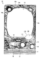
図1,図3に示されるように、前枠14における上球皿15の右側部には、可動演出装置100が取り付けられている。具体的に言うと、前枠14における上球皿15の右側部には金属ベース部材91(図3参照)が取り付けられており、可動演出装置100は、金属ベース部材91の設置部92に対して、左前方に傾斜した状態で取り付けられている。さらに、可動演出装置100は、カバー部材110によって覆われているため、遊技者が触れることはできないようになっている。
(3) Configuration of
図3,図4に示されるように、可動演出装置100は、略半球状をなす装置本体101を備えている。装置本体101は、略円板状をなすベース体102と、同ベース体102に取り付けられる略半球状の装飾体103とを備えている。装飾体103は、光透過性を有する樹脂材料によって形成され、外側面にめっき等の表面処理が施されている。
As shown in FIGS. 3 and 4, the
また、カバー部材110は、透明な樹脂材料によって形成され、カバー本体111、第1取付片部112及び第2取付片部113を備えている。カバー本体111は、略半球状をなし、可動演出装置100を覆うようになっている。第1取付片部112及び第2取付片部113は、カバー本体111の両側部にそれぞれ設けられ、カバー本体111の外周縁から外方にそれぞれ延出している。第1取付片部112は、金属ベース部材91に設けられた第1固定部93に固定され、第2取付片部113は、同じく金属ベース部材91に設けられた第2固定部94に固定されるようになっている。
The
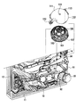
(3−1)送風装置120の構成
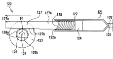
図4,図5に示されるように、可動演出装置100は、遊技者に空気を送る『送風手段』である送風装置120を備えている。送風装置120はピストン機構121を備え、ピストン機構121は、シリンダ本体122、モータ123及びピストン124を備えている。シリンダ本体122は、基端側において開口する略円筒状をなしており、内径が小さく設定された開口端部122aを有している。また、ピストン124は、略円柱状をなし、第1位置(図8参照)と第2位置(図5参照)との間でシリンダ本体122内を往復動することにより、シリンダ本体122外に空気を押し出すようになっている。ここで、「第1位置」とは、シリンダ本体122内の容積が最大となる押出待機位置をいう。一方、「第2位置」とは、シリンダ本体122内の容積が最小となる押出位置をいう。
(3-1) Configuration of
さらに、ピストン124は、モータ123の回転軸125に連結されている。詳述すると、ピストン124は、モータ123の回転軸125に連結されたピニオンギヤ126と、ピストン124の裏側から突出し、ピニオンギヤ126に噛み合うラックギヤ127とを介して、モータ123によって駆動されるようになっている。なお、ピニオンギヤ126の外周部の一部には、歯126aを有しない切欠部126bが形成されている。また、ラックギヤ127は、ピストン124の裏側に接続される接続部127aと、接続部127aよりもピニオンギヤ126寄りに設けられ、一側部(図5では下側部)に複数の歯127bが形成されたギヤ部127cとを有している。
Further, the
図5に示されるように、ピストン機構121は、第1位置から第2位置に向けてピストン124を付勢する『付勢部材』であるバネ128を備えている。バネ128は、シリンダ本体122内に収容されるとともに、ラックギヤ127の接続部127aに外挿されている。また、バネ128は、一方の端部がシリンダ本体122の開口端部122aに当接するとともに、他方の端部がピストン124の裏面(接続部127aとの接続面)に当接するようになっている。
As shown in FIG. 5, the
図4,図5に示されるように、送風装置120は送風ユニット130を備え、送風ユニット130は、送風口131、送風管132及び空気噴出口133を備えている。送風口131は、シリンダ本体122において開口端部122aとは反対側の端部に設けられており、シリンダ本体122の内外を連通させるようになっている。送風管132は、基端部が送風口131に接続されるとともに、先端側が可動演出装置100とカバー部材110との隙間に挿入されている。送風管132は、送風口131を介してシリンダ本体122内から押し出された空気を通過させるためのものである。空気噴出口133は、カバー部材110のカバー本体111の中央部に貫通形成されており、送風管132の先端部が接続されている。空気噴出口133は、送風管132を通過した空気を遊技者側に向けて噴出させるためのものである。
As shown in FIGS. 4 and 5, the
(4)パチンコ機10の電気的構成
図6に示されるように、このパチンコ機10は、主制御基板21、統括制御基板22、表示制御基板23及び音声・ランプ制御基板24を備えている。主制御基板21には統括制御基板22が電気的に接続され、統括制御基板22には、表示制御基板23及び音声・ランプ制御基板24が電気的に接続されている。
(4) Electrical Configuration of
(4−1)主制御基板21の電気的構成
主制御基板21は、パチンコ機10全体を制御するメインCPU21aを備えている。メインCPU21aには、始動口スイッチSE1、カウントスイッチSE2、ゲートスイッチSE3、左下入賞口スイッチSE4及び右下入賞口スイッチSE5が接続されている。また、メインCPU21aには、特別図柄表示装置61、普通電動役物ソレノイドSOL1及び大入賞口ソレノイドSOL2が接続されている。
(4-1) Electrical Configuration of
図6に示されるように、メインCPU21aには、メインROM(図示略)及びメインRAM(図示略)が電気的に接続されている。メインCPU21aは、特別図柄変動ゲームに係る各種抽選に用いる大当り判定用乱数、大当り図柄用乱数、リーチ判定用乱数、変動パターン振分乱数などの各種乱数の値を所定の周期ごとに更新している。そして、メインCPU21aは、更新後の値をメインRAMの乱数記憶領域に設定して更新前の値を書き換えている。また、メインRAMのタイマ記憶領域には、パチンコ機10の動作中に適宜書き換えられる各種のタイマが記憶(設定)されるようになっている。
As shown in FIG. 6, a main ROM (not shown) and a main RAM (not shown) are electrically connected to the
なお、大当り判定用乱数は、変動ゲームが大当りか否かを判定する際(大当り判定時)に用いられる乱数である。大当り図柄用乱数は、変動ゲームの結果が大当りとなる場合に特別図柄を決定する際に用いられる乱数である。リーチ判定用乱数は、変動ゲームの結果がハズレとなる場合にリーチ演出を実行させるか否かを決定する際(リーチ判定時)に用いられる乱数である。変動パターン振分乱数は、変動ゲームにおける遊技演出の演出内容を特定するための変動パターンを決定する際に用いられる乱数である。 The big hit determination random number is a random number used when determining whether or not the variable game is a big hit (when determining the big hit). The jackpot symbol random number is a random number used when determining a special symbol when the result of the variable game is a jackpot. The reach determination random number is a random number used when determining whether or not to execute the reach effect when the result of the floating game is lost (during reach determination). The variation pattern distribution random number is a random number used when determining the variation pattern for specifying the contents of the effect of the game effect in the variation game.
また、メインROMには、演出図柄変動ゲーム用の変動パターンが振り分けられた変動パターン振分テーブルが記憶されている。本実施形態の変動パターン振分テーブルには、ハズレ演出用の変動パターン、ハズレリーチ演出用の変動パターン、及び、大当り演出用の変動パターンが振り分けられている。なお、各変動パターンは、図柄表示装置60に表示される各列の図柄(演出図柄)が変動を開始(演出図柄変動ゲームを開始)してから全列の図柄が停止(演出図柄変動ゲームが終了)するまでの間の遊技演出(表示演出、発光演出、音声演出)の時間及び内容を特定するためのものである。また、各変動パターンには、変動パターン振分乱数の値(本実施形態では0〜99の100通りの整数)が振り分けられている。なお、ハズレ演出用の変動パターンは、ハズレの図柄組み合わせ(大当りまたはリーチとなる図柄組み合わせが導出されない図柄組み合わせ)を導出する演出のベースとなるパターンを示している。ハズレリーチ演出用の変動パターンは、リーチ演出を経てハズレの図柄組み合わせ(中図柄が、左図柄及び右図柄とは異なる図柄で停止する図柄組み合わせ)を表示させる演出のベースとなるパターンを示している。大当り演出用の変動パターンは、リーチ演出を経て大当りの図柄組み合わせ(中図柄が、左図柄及び右図柄と同一の図柄で停止する図柄組み合わせ)を表示させる演出のベースとなるパターンを示している。 The main ROM stores a variation pattern distribution table in which variation patterns for the effect symbol variation game are allocated. In the variation pattern distribution table of this embodiment, a variation pattern for a loss effect, a variation pattern for a loss reach effect, and a variation pattern for a jackpot effect are distributed. In addition, each variation pattern has the symbols in all the columns displayed on the symbol display device 60 (the effect symbol) start changing (the effect symbol variation game is started), and the symbols in all the columns are stopped (the effect symbol variation game is This is for specifying the time and contents of the game effect (display effect, light emission effect, sound effect) until the end). Each variation pattern is assigned a variation pattern distribution random number value (100 integers from 0 to 99 in this embodiment). It should be noted that the variation pattern for losing effect indicates a pattern serving as a base of the effect for deriving a symbol combination of losing symbols (a symbol combination from which a symbol combination that is a big hit or reach is not derived). The variation pattern for losing reach production shows the pattern that is the base of the production that displays the losing symbol combination (the symbol combination where the middle symbol stops at a different symbol from the left and right symbols) after reaching the reach. . The variation pattern for the jackpot effect indicates a pattern serving as a base for the effect of displaying the jackpot symbol combination (the symbol symbol combination in which the middle symbol stops at the same symbol as the left symbol and the right symbol) through the reach effect.
次に、図6に示されるメインCPU21aが実行する特別図柄変動ゲームに係る各種処理(大当り判定、リーチ判定、大当り図柄、ハズレ図柄、変動パターンの決定など)を説明する。
Next, various processes related to the special symbol variation game executed by the
まず、メインCPU21aは、始動口スイッチSE1からの入賞信号が入力されたか否かを判定する。入賞信号が入力されたと判定された場合、メインCPU21aは、特別図柄変動ゲームを実行させる制御を行う。具体的に言うと、メインCPU21aは、乱数抽選によって抽出されて所定の周期ごとに更新される大当り図柄用乱数の値をメインRAMから取得し、取得した値をメインRAMの乱数記憶領域に格納(記憶)する。また、メインCPU21aは、始動入賞条件の成立を契機として、乱数抽選によって抽出されて所定の周期ごとに更新される大当り判定用乱数の値をメインRAMから取得し、取得した値をメインRAMの乱数記憶領域に格納(記憶)する。
First, the
そして、図6に示されるメインCPU21aは、特別図柄変動ゲームの開始直前に、メインRAMの乱数記憶領域に格納されている大当り判定用乱数の値とメインROMに記憶されている大当り判定値とを比較して、特別図柄変動ゲームの当否を判定する大当り判定(大当り抽選)を行う。なお、本実施形態では、大当り判定用乱数の採りうる数値を0〜599(全600通りの整数)としている。そして、メインCPU21aは、大当り判定用乱数の採りうる数値の中から2個の大当り判定値を用いて、大当りの抽選確率を600分の2(=300分の1)として大当り判定を行う。
Then, the
大当り判定の判定結果が否定(大当り判定用乱数の値と大当り判定値とが不一致)の場合、メインCPU21aはハズレを決定する。そして、メインCPU21aは、ハズレを示す「−」の図柄を特別図柄として決定する。さらに、メインCPU21aは、決定した特別図柄に対応したデータを、次回の特別図柄変動ゲームに係る処理を行うまでの間、メインRAMに記憶する。
When the determination result of the big hit determination is negative (the value of the big hit determination random number does not match the big hit determination value), the
そして、図6に示されるメインCPU21aは、大当り判定による判定結果がハズレとなる場合に、メインRAMから読み出したリーチ判定用乱数の値とメインROMに記憶されているリーチ判定値とを比較してハズレリーチを実行するか否かのリーチ判定を行う。なお、本実施形態では、リーチ判定用乱数の採りうる数値を0〜180(全181通りの整数)としている。また、リーチ判定値は、リーチ判定用乱数の採りうる数値の中からあらかじめ定めた値である。そして、リーチ判定の判定結果が肯定(リーチ判定用乱数の値とリーチ判定値とが一致)の場合、メインCPU21aはハズレリーチを決定する。また、リーチ判定の判定結果が否定(リーチ判定用乱数の値とリーチ判定値とが不一致)の場合、メインCPU21aはハズレ(リーチを伴わないハズレ)を決定する。
The
一方、大当り判定の判定結果が肯定(大当り判定用乱数の値と大当り判定値とが一致)の場合、図6に示されるメインCPU21aは大当りを決定する。大当りの決定がなされると、メインCPU21aは、メインRAMの乱数記憶領域に記憶された大当り図柄用乱数の値に基づいて、「0」〜「9」のいずれか1つを示す特別図柄を決定する。そして、メインCPU21aは、決定した特別図柄に対応したデータを、次回の特別図柄変動ゲームに係る処理を行うまでの間、メインRAMに記憶する。
On the other hand, when the determination result of the big hit determination is affirmative (the value of the random number for big hit determination matches the big hit determination value), the
また、メインCPU21aは、メインRAMの乱数記憶領域に記憶された大当り図柄用乱数の値に基づいて、特別図柄が確変図柄であるか非確変図柄であるかを判定する。本実施形態では、大当り図柄用乱数の値が「1」,「3」,「5」,「7」,「9」のいずれかであれば、特別図柄が確変図柄であると判定され、大当り図柄用乱数の値が「0」,「2」,「4」,「6」,「8」のいずれかであれば、特別図柄が非確変図柄であると判定される。そして、特別図柄が確変図柄であると判定された場合に、後述する大当り遊技状態の終了後に開始される特別図柄変動ゲームにおいて、確率変動状態を付与するようになっている。一方、メインCPU21aは、特別図柄が非確変図柄であると判定された場合に、大当り遊技状態の終了後に開始される特別図柄変動ゲームにおいて、通常遊技状態を付与するようになっている。
Further, the
そして、特別図柄変動ゲームにおいて確率変動状態が付与された場合、図6に示されるメインCPU21aは、大当り判定用乱数の採りうる数値の中から20個の大当り判定値を用いて、大当りの抽選確率を600分の20(=30分の1)として大当り判定を行う。即ち、確率変動状態時の大当り判定値の数は、確率変動状態前の10倍となる。なお、確率変動状態は、次回の大当り遊技状態が開始されるまでの間、継続されるようになっていてもよいし、複数回(例えば10000回)の図柄の変動表示が実行されるまでの間、継続されるようになっていてもよい。
Then, when the probability variation state is given in the special symbol variation game, the
また、メインCPU21aは、大当り判定及びリーチ判定の判定結果に基づいて変動パターンを決定する。具体的に言うと、大当り判定において大当りが決定された場合、メインCPU21aは、メインRAMから変動パターン振分乱数の値を読み出し、該値に基づき、変動パターン振分テーブルに記憶されている大当り演出用の変動パターンを決定する。リーチ判定においてハズレリーチが決定された場合、メインCPU21aは、メインRAMから読み出した変動パターン振分乱数の値に基づき、変動パターン振分テーブルからハズレリーチ演出用の変動パターンを決定する。リーチ判定においてハズレが決定された場合、メインCPU21aは、メインRAMから読み出した変動パターン振分乱数の値に基づき、変動パターン振分テーブルからハズレ演出用の変動パターンを決定する。
Further, the
さらに、図6に示されるメインCPU21aは、特別図柄表示装置61に特別図柄を表示させる制御を行う。詳述すると、メインCPU21aは、特別図柄及び変動パターンを決定すると、変動パターンごとに対応付けられた変動時間を特別図柄タイマとしてメインRAMのタイマ記憶領域に設定(記憶)し、特別図柄表示装置61に特別図柄の変動を開始させる。
Further, the
また、メインCPU21aは、最初に、変動パターンを指定するとともに図柄の変動開始を指示する変動パターン指定コマンドを生成し、制御コマンドとして設定(メインRAMに記憶)する。そして、ここでセットされた制御コマンドは、次回以降のコマンド出力処理で出力される。次に、メインCPU21aは、特別図柄を指定する特別図柄指定コマンドを、制御コマンドとして設定(メインRAMに記憶)する。そして、ここでセットされた制御コマンドは、次回以降のコマンド出力処理で出力される。また、メインCPU21aは、変動開始時に設定した特別図柄タイマを割込み(4ms)ごとに減算する。そして、特別図柄タイマが0msになると、メインCPU21aは、特別図柄及び演出図柄の停止を指示する図柄停止コマンドを、制御コマンドとして設定(出力)する。
The
さらに、図6に示されるメインCPU21aは、大当り判定による判定結果が大当りとなる場合に、大入賞装置52が開放状態となる大当り遊技状態を付与するようになっている。なお、大当り遊技状態では、1回のオープニング演出と、10回のラウンド演出と、1回のエンディング演出とが実行される。オープニング演出は、大入賞装置52が閉鎖状態である場合であって、大当り遊技状態が開始されるときに実行されるようになっている。各ラウンド演出は、大入賞口ソレノイドSOL2の励磁作用によって大入賞装置52が閉鎖状態から開放状態に切り替えられる場合に実行されるようになっている。1回当りのラウンド演出は、大入賞装置52が開放状態に切り替えられてから閉鎖状態に切り替えられるまでの間に実行されるようになっている。また、エンディング演出は、大入賞装置52が開放状態から閉鎖状態に切り替えられる場合であって、大当り遊技状態が終了するとき(本実施形態では、10回目のラウンド演出の終了時)に実行されるようになっている。
Further, the
そして、図6に示されるメインCPU21aは、図柄停止コマンドが出力された後に、オープニング演出の開始を指示するオープニング指定コマンドを生成し、制御コマンドとして出力する。次に、メインCPU21aは、第1〜第10のラウンド演出の開始を指示するラウンド指定コマンドを制御コマンドとして順番に出力する。その後、メインCPU21aは、エンディング演出の開始を指示するエンディング指定コマンドを、制御コマンドとして出力する。
Then, after the symbol stop command is output, the
(4−2)統括制御基板22の電気的構成
統括制御基板22は統括制御CPU22aを備えており、統括制御CPU22aには送風装置120が接続されている。また、統括制御CPU22aには、統括ROM(図示略)及び統括RAM(図示略)が電気的に接続されている。統括制御CPU22aは、遊技演出の決定のために用いる各種乱数の値を所定の周期ごとに更新している。そして、統括制御CPU22aは、更新後の値を統括RAMの設定領域に設定して更新前の値を書き換えている。例えば、統括RAMの乱数記憶領域には、ハズレ左図柄用乱数、ハズレ中図柄用乱数、ハズレ右図柄用乱数などが記憶されている。統括RAMのタイマ記憶領域には、パチンコ機10の動作中に適宜書き換えられる各種のタイマが記憶(設定)されるようになっている。
(4-2) Electrical configuration of the
ところで、変動パターン指定コマンドが入力されると、図6に示される統括制御CPU22aは、変動パターン指定コマンドにて指定された変動パターンを統括RAMに記憶するようになっている。また、特別図柄指定コマンドが入力されると、統括制御CPU22aは、特別図柄指定コマンドが指定する特別図柄を統括RAMに記憶するようになっている。
Incidentally, when a variation pattern designation command is input, the
さらに、統括制御CPU22aは、統括RAMに記憶されている特別図柄と変動パターンとに基づいて、演出図柄変動ゲームの終了時に図柄表示装置60に停止表示される演出図柄を生成するようになっている。例えば、統括RAMに記憶されている特別図柄が「0」〜「9」のいずれかであって、統括RAMに記憶されている変動パターンが大当り演出用の変動パターンである場合、統括制御CPU22aは大当りを決定する。この場合、統括制御CPU22aは、図柄表示装置60に最終的に停止させる演出図柄(演出図柄左、中、右)を、全列が同一種類の図柄となるように生成する。具体的に言うと、統括制御CPU22aは、特別図柄に基づいて、演出図柄左、演出図柄中及び演出図柄右(各演出図柄は同一種類)を生成する。例えば、特別図柄が「1」であれば演出図柄を「1」とし、特別図柄が「2」であれば演出図柄を「2」とする。この生成された演出図柄(演出図柄左、中、右)が、図柄表示装置60に最終的な組み合わせとして導出される。そして、統括制御CPU22aは、生成した演出図柄左、演出図柄中、演出図柄右に対応したデータを統括RAMに記憶する。
Furthermore, the
統括RAMに記憶されている特別図柄が「−」であって、統括RAMに記憶されている変動パターンがハズレリーチ演出用の変動パターンである場合、図6に示される統括制御CPU22aはハズレリーチを決定する。この場合、統括制御CPU22aは、演出図柄左、中、右を、左列と右列が同一種類の図柄で、中列が左右2列とは異なる種類の図柄となるように決定する。具体的には、ハズレ左図柄用乱数の値に基づいて演出図柄左及び演出図柄右(両演出図柄は同一種類)を生成する。そして、ハズレ中図柄用乱数の値に基づいて演出図柄中を生成する。そして、統括制御CPU22aは、生成した演出図柄左、演出図柄中、演出図柄右に対応したデータを統括RAMに記憶する。本実施形態では、ハズレ左図柄用乱数、ハズレ右図柄用乱数及びハズレ中図柄用乱数の各乱数の採りうる数値を0〜9の10通りの整数とし、図柄の種類ごとに1つの数値が対応付けられている。
When the special symbol stored in the overall RAM is “−” and the variation pattern stored in the overall RAM is the variation pattern for the lost reach production, the
統括RAMに記憶されている特別図柄が「−」であって、統括RAMに記憶されている変動パターンがハズレ演出用の変動パターンである場合、図6に示される統括制御CPU22aはハズレを決定する。この場合、統括制御CPU22aは、演出図柄左、中、右を、全列が同一種類の図柄とならないように(即ち、大当りの図柄組み合わせとならないように)生成する。また、統括制御CPU22aは、演出図柄左、中、右を、リーチの図柄組み合わせとならないように生成する。そして、統括制御CPU22aは、生成した演出図柄左、演出図柄中、演出図柄右に対応したデータを統括RAMに記憶する。
If the special symbol stored in the overall RAM is “−” and the variation pattern stored in the overall RAM is a variation pattern for a loss effect, the
なお、統括制御CPU22aは、統括RAMに記憶されている変動パターンを指定する変動パターン指定コマンドを、制御コマンドとして表示制御基板23の表示制御CPU23a、及び、音声・ランプ制御基板24の音声・ランプ制御CPU24aに出力する。これにより、表示制御基板23及び音声・ランプ制御基板24が実行する遊技演出の具体的な内容が、統括制御基板22によって統括的に制御される。
The
さらに、図6に示される統括制御CPU22aは、演出図柄の演出図柄左を指定する演出図柄左指定コマンドを、制御コマンドとして表示制御CPU23aに出力する。同様に、統括制御CPU22aは、演出図柄の演出図柄右を指定する演出図柄右指定コマンド、及び、演出図柄の演出図柄中を指定する演出図柄中指定コマンドを、制御コマンドとして表示制御CPU23aに出力する。その後、メインCPU21aから図柄停止コマンドが入力されると、統括制御CPU22aは、入力された図柄停止コマンドを、制御コマンドとして表示制御CPU23a及び音声・ランプ制御CPU24aに出力する。
Further, the
また、統括制御CPU22aは、特別図柄変動ゲーム中に実行される演出の種類を決定する。具体的に言うと、統括制御CPU22aは、変動開始時に入力されて統括RAMに記憶されている変動パターンが、大当り演出(特定演出)用の変動パターンであるか否かを判定する。そして、統括RAMに記憶されている変動パターンが大当り演出用の変動パターンであると判定された場合、統括制御CPU22aは、送風装置120を作動させる送風演出の実行を決定する。即ち、統括制御CPU22aは、『演出決定手段』としての機能を有している。
In addition, the
そして、送風演出の実行が決定された場合、図6に示される統括制御CPU22aは、送風演出の開始前(本実施形態では、大当りとなる特別図柄変動ゲームの開始前)に、ピストン124を第1位置(図8参照)で保持させる制御を行う。具体的に言うと、統括制御CPU22aは、送風装置120のモータ123に対して駆動信号を出力して、回転軸125及びピニオンギヤ126を反時計回り方向(図7に示す矢印F1方向)に回転させることにより、ピストン124を第2位置(図5参照)から第1位置に移動させる。そして、ピストン124が第1位置に到達すると、統括制御CPU22aは、モータ123に停止信号を出力してモータ123を停止させることにより、ピストン124を第1位置で停止させる。その結果、ピストン124が第1位置で保持されるようになる。なお、本実施形態のモータ123は、ピストン機構121を構成するモータと同じものであり、『保持手段』としての機能も有している。
When the execution of the airing effect is determined, the
その後、統括制御CPU22aは、特別図柄変動ゲームにおいてリーチ演出が開始される際に、送風演出を開始させる制御を行う。即ち、統括制御CPU22aは、『送風演出実行制御手段』としての機能を有している。具体的に言うと、統括制御CPU22aは、モータ123に対して再度駆動信号を出力して、回転軸125及びピニオンギヤ126を再び反時計回り方向に回転させる。その結果、送風装置120は、駆動信号に基づき送風演出(ピストン124の往復動など)を行うことができるようになる。
Thereafter, the
また、メインCPU21aからオープニング指定コマンドが入力されると、図6に示される統括制御CPU22aは、入力されたオープニング指定コマンドを、制御コマンドとして表示制御CPU23a及び音声・ランプ制御CPU24aに出力する。次に、メインCPU21aから第1〜第10のラウンド演出用のラウンド指定コマンドが入力されると、統括制御CPU22aは、入力された各ラウンド指定コマンドを、制御コマンドとして表示制御CPU23a及び音声・ランプ制御CPU24aに出力する。その後、メインCPU21aからエンディング指定コマンドが入力されると、統括制御CPU22aは、入力されたエンディング指定コマンドを、制御コマンドとして表示制御CPU23a及び音声・ランプ制御CPU24aに出力する。
When an opening designation command is input from the
(4−3)表示制御基板23の電気的構成
図6に示されるように、表示制御基板23は表示制御CPU23aを備えており、表示制御CPU23aには表示ROM(図示略)及び表示RAM(図示略)が接続されている。表示RAMには、パチンコ機10の動作中に適宜書き換えられる各種の情報が一時的に記憶(設定)されるようになっている。
(4-3) Electrical Configuration of
また、表示ROMには、演出図柄変動ゲームが行われる際に用いられる複数種類の表示演出データが記憶されている。表示演出データとは、表示制御CPU23aが、図柄表示装置60の表示内容(図柄変動など)を制御するための情報、即ち、図柄表示装置60に表示演出の実行を指示するための情報である。
The display ROM stores a plurality of types of display effect data used when the effect symbol variation game is performed. The display effect data is information for the
さらに、表示ROMには、演出図柄変動ゲーム後の大当り遊技状態において用いられる1種類のオープニング演出用表示演出データ、10種類のラウンド演出用表示演出データ、及び、1種類のエンディング演出用表示演出データが記憶されている。オープニング演出用表示演出データは、オープニング演出に対応付けて記憶されている。各ラウンド演出用表示演出データは、第1〜第10のラウンド演出ごとに対応付けられて記憶されている。エンディング演出用表示演出データは、エンディング演出に対応付けられて記憶されている。オープニング演出用表示演出データ、ラウンド演出用表示演出データ及びエンディング演出用表示演出データとは、表示制御CPU23aが、図柄表示装置60にオープニング演出、ラウンド演出及びエンディング演出の実行を指示するための情報である。
Further, the display ROM includes one kind of opening effect display effect data, ten kinds of round effect display effect data, and one kind of ending effect display effect data used in the big hit gaming state after the effect symbol variation game. Is remembered. The display effect data for opening effects is stored in association with the opening effects. Each round effect display effect data is stored in association with each of the first to tenth round effects. The display effect data for ending effect is stored in association with the ending effect. The display effect data for opening effect, the display effect data for round effect, and the display effect data for ending effect are information for the
そして、図6に示される統括制御CPU22aから変動パターン指定コマンドが入力されると、表示制御CPU23aは、変動パターン指定コマンドにて指定された変動パターンを表示RAMに記憶するようになっている。また、表示制御CPU23aは、統括制御CPU22aから演出図柄左指定コマンドが入力されると、同コマンドが指定する演出図柄左を表示RAMに記憶するようになっている。同様に、表示制御CPU23aは、統括制御CPU22aから演出図柄右指定コマンドが入力されると、同コマンドが指定する演出図柄右を表示RAMに記憶し、演出図柄中指定コマンドが入力されると、同コマンドが指定する演出図柄中を表示RAMに記憶するようになっている。
When a variation pattern designation command is input from the
その後、統括制御CPU22aから図柄停止コマンドが入力されると、表示制御CPU23aは、変動開始時に入力されて表示RAMに記憶された演出図柄左、右、中に基づいて、図柄表示装置60に演出図柄の停止を指示するようになっている。これにより、指定された演出図柄が停止して、図柄表示装置60に表示される。
After that, when a symbol stop command is input from the
また、変動パターン指定コマンドが入力されると、図6に示される表示制御CPU23aは、表示ROMに記憶された複数種類の表示演出データのうちいずれか1つを設定(生成)して、設定した表示演出データを表示RAMの記憶領域に記憶させるようになっている。これにより、表示制御CPU23aは、変動パターン指定コマンドや表示演出データに基づいて表示制御を行うようになる。より詳しくは、表示制御CPU23aは、表示RAMに記憶されている表示演出データを図柄信号に変換し、図柄表示装置60に出力する。その結果、図柄表示装置60は、図柄信号に基づき所定の表示(演出図柄変動ゲームなど)を行うことができるようになる。
When the variation pattern designation command is input, the
さらに、オープニング指定コマンドが入力されると、表示制御CPU23aは、表示ROMに記憶されたオープニング演出用表示演出データを設定(生成)して、設定したオープニング演出用表示演出データを表示RAMの記憶領域に記憶させるようになっている。これにより、表示制御CPU23aは、オープニング指定コマンドやオープニング演出用表示演出データに基づいて表示制御を行うようになる。ラウンド指定コマンドが入力されると、表示制御CPU23aは、表示ROMに記憶された10種類のラウンド演出用表示演出データのうちいずれか1つを設定(生成)して、設定したラウンド演出用表示演出データを表示RAMの記憶領域に記憶させるようになっている。これにより、表示制御CPU23aは、ラウンド指定コマンドやラウンド演出用表示演出データに基づいて表示制御を行うようになる。エンディング指定コマンドが入力されると、表示制御CPU23aは、表示ROMに記憶されたエンディング演出用表示演出データを設定(生成)して、設定したエンディング演出用表示演出データを表示RAMの記憶領域に記憶させるようになっている。これにより、表示制御CPU23aは、エンディング指定コマンドやエンディング演出用表示演出データに基づいて表示制御を行うようになる。より詳しくは、表示制御CPU23aは、表示RAMに記憶されているオープニング演出用表示演出データ、ラウンド演出用表示演出データ及びエンディング演出用表示演出データを図柄信号に変換し、図柄表示装置60に出力する。その結果、図柄表示装置60は、図柄信号に基づき所定の表示を行うことができるようになる。
Further, when an opening designation command is input, the
(4−4)音声・ランプ制御基板24の電気的構成
図6に示されるように、音声・ランプ制御基板24は音声・ランプ制御CPU24aを備えており、音声・ランプ制御CPU24aには音声・ランプROM(図示略)及び音声・ランプRAM(図示略)が接続されている。音声・ランプRAMには、パチンコ機10の動作中に適宜書き換えられる各種の情報が一時的に記憶(設定)されるようになっている。
(4-4) Electrical configuration of voice /
また、音声・ランプROMには、演出図柄変動ゲームが行われる際に用いられる複数種類の発光演出データ及び複数種類の音声演出データが記憶されている。発光演出データとは、音声・ランプ制御CPU24aが、枠ランプ16a〜16cの発光出力態様を制御するための情報である。また、音声演出データとは、音声・ランプ制御CPU24aが、スピーカ17(図6参照)の音声出力態様(効果音の種類、言語音声の種類、音声出力時間など)を制御するための情報である。なお、スピーカ17は、各種音声を出力して音声演出を行うためのものである。
The voice / lamp ROM stores a plurality of types of light emission effect data and a plurality of types of sound effect data used when the effect symbol variation game is performed. The light effect data is information for the sound /
さらに、音声・ランプROMには、演出図柄変動ゲーム後の大当り遊技状態において用いられる1種類のオープニング演出用演出データ、10種類のラウンド演出用演出データ、及び、1種類のエンディング演出用演出データが記憶されている。オープニング演出用演出データは、オープニング演出に対応付けて記憶されている。各ラウンド演出用演出データは、第1〜第10のラウンド演出に対応付けて記憶されている。エンディング演出用演出データは、エンディング演出に対応付けて記憶されている。オープニング演出用演出データ、ラウンド演出用演出データ及びエンディング演出用演出データとは、音声・ランプ制御CPU24aが、枠ランプ16a〜16c及びスピーカ17にオープニング演出、ラウンド演出及びエンディング演出の実行を指示するための情報である。
Furthermore, in the voice / lamp ROM, there is one type of opening production effect data, 10 types of round production effect data, and one type of ending production effect data used in the big hit gaming state after the production symbol variation game. It is remembered. The effect data for opening effects is stored in association with the opening effects. Each round effect data is stored in association with the first to tenth round effects. Ending effect data is stored in association with the ending effect. The effect data for opening effect, the effect data for round effect, and the effect data for ending effect are for the voice /
そして、図6に示される統括制御CPU22aから変動パターン指定コマンドが入力されると、音声・ランプ制御CPU24aは、変動パターン指定コマンドにて指定された変動パターンを音声・ランプRAMに記憶するようになっている。その後、統括制御CPU22aから図柄停止コマンドが入力されると、音声・ランプ制御CPU24aは、枠ランプ16a〜16cの発光停止を指示するとともに、スピーカ17の音声出力停止を指示するようになっている。
When a fluctuation pattern designation command is input from the
また、変動パターン指定コマンドが入力されると、音声・ランプ制御CPU24aは、音声・ランプROMに記憶された複数種類の発光演出データのうちいずれか1つを設定(生成)して、設定した発光演出データを音声・ランプRAMの記憶領域に記憶させるようになっている。これにより、音声・ランプ制御CPU24aは、変動パターン指定コマンドに対応する発光演出データに基づいて発光制御を行うようになる。より詳しくは、音声・ランプ制御CPU24aは、音声・ランプRAMに記憶されている発光演出データを発光制御信号に変換し、枠ランプ16a〜16cに出力する。その結果、枠ランプ16a〜16cは、発光制御信号に基づき所定の発光動作(点灯、点滅など)を行うことができるようになる。
When a change pattern designation command is input, the sound /
また、変動パターン指定コマンドが入力されると、図6に示される音声・ランプ制御CPU24aは、音声・ランプROMに記憶された複数種類の音声演出データのうちいずれか1つを設定(生成)して、設定した音声演出データを音声・ランプRAMの記憶領域に記憶させるようになっている。これにより、音声・ランプ制御CPU24aは、変動パターン指定コマンドに対応する音声演出データに基づいて音声制御を行うようになる。より詳しくは、音声・ランプ制御CPU24aは、音声・ランプRAMに記憶されている音声演出データを音声信号に変換し、スピーカ17に出力する。その結果、スピーカ17は、音声信号に基づき所定の出力動作(音声の出力)を行うことができるようになる。
When a variation pattern designation command is input, the voice /
さらに、オープニング指定コマンドが入力されると、音声・ランプ制御CPU24aは、音声・ランプROMに記憶されたオープニング演出用演出データを設定(生成)して、設定したオープニング演出用演出データを音声・ランプRAMの記憶領域に記憶させるようになっている。これにより、音声・ランプ制御CPU24aは、オープニング指定コマンドやオープニング演出用演出データに基づいて発光制御や音声制御を行うようになる。ラウンド指定コマンドが入力されると、音声・ランプ制御CPU24aは、音声・ランプROMに記憶されたラウンド演出用演出データを設定(生成)して、設定したラウンド演出用演出データを音声・ランプRAMの記憶領域に記憶させるようになっている。これにより、音声・ランプ制御CPU24aは、ラウンド指定コマンドやラウンド演出用演出データに基づいて発光制御や音声制御を行うようになる。エンディング指定コマンドが入力されると、音声・ランプ制御CPU24aは、音声・ランプROMに記憶されたエンディング演出用演出データを設定(生成)して、設定したエンディング演出用演出データを音声・ランプRAMの記憶領域に記憶させるようになっている。これにより、音声・ランプ制御CPU24aは、エンディング指定コマンドやエンディング演出用演出データに基づいて発光制御や音声制御を行うようになる。より詳しくは、音声・ランプ制御CPU24aは、音声・ランプRAMに記憶されているオープニング演出用演出データ、ラウンド演出用演出データ及びエンディング演出用演出データを発光制御信号や音声信号に変換し、枠ランプ16a〜16cやスピーカ17に出力する。その結果、枠ランプ16a〜16cやスピーカ17は、発光制御信号や音声信号に基づき所定の発光や音声出力を行うことができるようになる。
Further, when an opening designation command is input, the sound /
次に、送風演出について説明する。 Next, the air blowing effect will be described.
まず、遊技者は、始動入賞装置51を狙って遊技球を発射する。そして、遊技球が始動入賞装置51に入賞すると、特別図柄変動ゲームの開始直前に、特別図柄変動ゲームの当否を判定する大当り判定が行われる。
First, the player launches a game ball aiming at the
大当り判定の判定結果が肯定の場合、特別図柄変動ゲームの結果が大当りになることが決定されるとともに、特別図柄変動ゲーム中に送風演出が実行されることが決定される。そして、送風演出の開始前(本実施形態では、大当り判定が終了したとき)にモータ123が作動する。具体的に言うと、まず、モータ123の回転軸125及びピニオンギヤ126が反時計回り方向(図7に示す矢印F1方向)に回転することにより、ピストン124が第2位置(図5参照)から第1位置(図8参照)に移動する。そして、ピストン124が第1位置に到達すると、モータ123が停止するとともに、ピストン124が第1位置で停止する。その結果、ピストン124が第1位置で保持されるようになる。なお、第1位置では、モータ123側のピニオンギヤ126とピストン124側のラックギヤ127とが、少しだけ噛み合った状態となる。
If the determination result of the big hit determination is affirmative, it is determined that the result of the special symbol variation game is a big hit and it is determined that the airing effect is executed during the special symbol variation game. Then, the
そして、特別図柄変動ゲームにおいてリーチ演出が開始されると、送風演出が開始される。具体的に言うと、まず、モータ123の回転軸125が再び反時計回り方向に回転する。このとき、ピニオンギヤ126とラックギヤ127との噛合状態が解除され、ピストン124は、バネ128の付勢力によって第2位置側に移動する(図9参照)。また、ピストン124の移動に伴い、ラックギヤ127のギヤ部127cは、ピニオンギヤ126の切欠部126b上を移動する。その結果、シリンダ本体122内の空気が、送風口131を介してシリンダ本体122外に押し出される。その後、シリンダ本体122外に押し出された空気は、送風管132内を通過し、空気噴出口133から遊技者側に噴出するようになる。つまり、遊技者は、リーチ演出の開始と同時に空気の噴出を感じ取ることにより、変動ゲームの結果が大当りになることを期待するようになる。即ち、本実施形態の送風演出は、大当り予告として用いられている。
Then, when the reach effect is started in the special symbol variation game, the air blowing effect is started. Specifically, first, the
その後、モータ123の回転軸125は、反時計回り方向に回転し続ける。詳述すると、ピストン124が第2位置にある状態で回転軸125が反時計回り方向に回転すると、ピニオンギヤ126とラックギヤ127とが再び噛合し、ピストン124が第2位置から第1位置に移動する。そして、ピストン124が第1位置に移動すると、ピニオンギヤ126とラックギヤ127との噛合状態が再び解除され、ピストン124は再び第2位置に移動する。即ち、ピストン124は、第1位置と第2位置との間でシリンダ本体122内を往復動するため、空気が連続的に発射されるようになる。
Thereafter, the
そして、リーチ演出が終了し、変動ゲームにおいて大当りが導出されると、モータ123及びピストン124が停止する。その結果、空気噴出口133から遊技者側への空気の噴出が終了する。
Then, when the reach effect is finished and the big hit is derived in the variable game, the
従って、本実施形態によれば以下のような効果を得ることができる。 Therefore, according to the present embodiment, the following effects can be obtained.
(1)本実施形態のパチンコ機10では、送風装置120が、モータ123の回転軸125の回転をピストン124の運動に変換し、ピストン124の往復動によってシリンダ本体122外に空気を押し出す構造となっている。このため、モータ123の回転速度を調整することにより、シリンダ本体122外に空気を素早く押し出すことができる。その結果、送風装置120から空気を素早く送ることができるため、遊技者は、送風装置120が作動するとほぼ同時に空気の噴出に気付くようになる。この場合、遊技者は、空気の噴出を事前に予測できないため、遊技者に強いインパクトを与えることが可能になる。
(1) In the
しかも、モータ123は、第1位置でピストン124を保持するため、モータ123による保持を解除してモータ123を駆動すると、すぐにシリンダ本体122内の空気が押し出されるようになる。ゆえに、モータ123の駆動音によって、空気の噴出が遊技者に事前に予測されてしまうといった事態をより確実に防止することができる。しかも、第1位置は、シリンダ本体122内の容積が最大となる位置であるため、モータ123の駆動開始時に第1位置からピストン124を駆動すると、送風装置120からは大量の空気が送られるようになる。その結果、遊技者は、空気の噴出に気付きやすくなるため、遊技者により強いインパクトを与えることができる。また、送風装置120は、モータ123の回転軸125を回転させるだけで、ピストン124が往復動して空気が押し出される構造を有しているため、空気を連続発射する際に有利である。
In addition, since the
(2)本実施形態における送風装置120の制御は、従来の可動部材(役物など)の制御と同じく、モータによる制御である。即ち、従来から用いられているモータの制御プログラムを用いて送風装置120を制御することができ、送風装置120の制御に複雑な制御プログラムを用いてなくても済むため、パチンコ機10の開発コストを抑えることができる。
(2) Control of the
(3)本実施形態の送風装置120では、単純なピストン124の運動によって空気を噴出させるものである。このため、空気圧をある程度高めてから発射するエアポンプ式の送風装置に比べて、空気を連続発射させる際に有利である。
(3) In the
なお、本実施形態を以下のように変更してもよい。 In addition, you may change this embodiment as follows.
・上記実施形態では、特別図柄変動ゲームの結果が大当りとなる場合に、送風演出が実行されるようになっていたが、他の条件に基づいて送風演出を実行するようにしてもよい。例えば、特別図柄変動ゲーム中にリーチ演出が実行される場合(即ち、特別図柄変動ゲームの結果が大当りとなる可能性がある場合)に、送風演出を実行するようにしてもよい。また、確率変動状態や変動時間短縮状態が付与される場合に、送風演出を実行するようにしてもよい。さらに、演出図柄変動ゲーム中や大当り遊技状態中に特定の演出(特別なキャラクタが出現する演出など)が実行される場合に、送風演出を実行するようにしてもよい。例えば、出現頻度が高く大当りとなる期待度が低い通常のキャラクタ(例えば、赤色のロボット)が表示される演出が実行される場合に、送風演出が実行される可能性を低くするとともに、出現頻度が低く大当りとなる期待度が高い特別なキャラクタ(例えば、金色のロボット)が表示される演出が実行される場合に、送風演出が実行される可能性を高くしてもよい。 In the above embodiment, when the result of the special symbol variation game is a big hit, the air blowing effect is executed. However, the air blowing effect may be executed based on other conditions. For example, when the reach effect is executed during the special symbol variation game (that is, when the result of the special symbol variation game may be a big hit), the air blowing effect may be performed. Further, when a probability variation state or a variation time shortening state is given, a blowing effect may be executed. Further, when a specific effect (such as an effect in which a special character appears) is executed during the effect symbol variation game or the big hit game state, the fan effect may be executed. For example, when an effect in which a normal character (for example, a red robot) with a high appearance frequency and a low expectation level is displayed is executed, the possibility of the airing effect being reduced is reduced and the appearance frequency is reduced. When a special character (for example, a golden robot) with a high expectation level that is low and a big hit is executed, the possibility that the air blowing effect is executed may be increased.
・上記実施形態では、統括制御CPU22aが、特別図柄変動ゲームの結果が大当りとなると判定された場合に、特別図柄変動ゲームの開始前に、ピストン124を第1位置で保持させる制御を行っていた。しかし、統括制御CPU22aは、他の条件に基づいて、ピストン124を第1位置で保持させる制御を行ってもよい。
In the above embodiment, the
例えば、統括制御CPU22aは、メインCPU21aによって特別図柄変動ゲームの結果が大当りとなると判定された場合に、特別図柄変動ゲーム後の大当り遊技状態中に、ピストン124を第1位置で保持させる制御を行ってもよい。また、統括制御CPU22aは、遊技者が遊技を行っていないデモンストレーション演出中である場合に、ピストン124を第1位置で保持させる制御を行ってもよい。このようにすれば、送風演出が開始される可能性がある期間、即ち、特別図柄変動ゲームの結果が大当りになることを期待する期間とは全く関係ないタイミングでピストン124を第1位置に保持させる制御を行うため、送風演出が遊技者に事前に予測されてしまうといった事態をよりいっそう確実に防止できる。
For example, when the
また、統括制御CPU22aは、パチンコ機10の電源投入時(具体的には、電源起動時の動作チェック後など)において、ピストン124を第1位置で保持させる制御を行ってもよい。この場合も、送風演出が遊技者に事前に予測されてしまうといった事態をよりいっそう確実に防止できる。
The
さらに、統括制御CPU22aは、送風演出の終了時において、ピストン124を第1位置で保持させる制御を行ってもよい。このようにすれば、次回の送風演出においても、送風装置120から空気をより素早く送ることができる。
Further, the
・上記実施形態では、ピストン機構121を構成するモータ123が『保持手段』として用いられていたが、例えば、ピストン機構121とは別体に設けられ、第1位置でラックギヤ127に係合するロックピンなどを、『保持手段』として用いてもよい。
In the above embodiment, the
・上記実施形態の送風装置120は、前枠14における上球皿15の右側部にある可動演出装置100内に組み込まれていた。しかし、送風装置を、外枠11、遊技盤13、操作ハンドル19、及び、前枠14や操作ハンドル19に設置される演出用の操作手段に対して組み込むようにしてもよい。なお、送風装置を遊技盤13に組み込む場合、送風装置は、遊技者に送風するためのものでなくてもよく、何らかの演出として送風するものであってもよい。
-The
・上記実施形態の送風装置120は、統括制御基板22の統括制御CPU22aに接続されていたが、表示制御基板23の表示制御CPU23aに接続されていてもよいし、音声・ランプ制御基板24の音声・ランプ制御CPU24aに接続されていてもよいし。即ち、送風装置120は、統括制御CPU22aによって制御可能な箇所に接続されていればよい。
The
・上記実施形態において、統括制御CPU22aは、所定条件下で、モータ123の回転軸125の回転速度を変更する制御を行ってもよい。例えば、特別図柄変動ゲームの結果が確率変動状態が付与される大当りである場合に、回転軸125の回転速度を速くするようにしてもよい。即ち、統括制御CPU22aは、モータ123の回転速度を変更する『回転速度変更制御手段』としての機能を有していてもよい。このようにすれば、条件に応じて空気の態様を変更できるため、遊技の多様化を図ることができ、遊技の興趣が向上する。
In the above embodiment, the
次に、特許請求の範囲に記載された技術的思想のほかに、前述した実施形態によって把握される技術的思想を以下に列挙する。 Next, in addition to the technical ideas described in the claims, the technical ideas grasped by the embodiment described above are listed below.
(1)請求項1乃至6のいずれか1つにおいて、図柄を変動させる図柄変動ゲームの結果が大当りとなるか否かを判定する大当り判定手段を備え、前記送風演出実行制御手段は、前記大当り判定手段による判定結果に基づいて、前記送風演出を実行させる制御を行うものであり、前記大当り判定手段によって前記図柄変動ゲームの結果が大当りとなると判定された場合に、図柄変動ゲーム後の大当り遊技状態中に、前記ピストンを前記第1位置で保持させる制御を行うことを特徴とする遊技機。 (1) According to any one of claims 1 to 6, further comprising a big hit determining means for determining whether or not the result of the symbol change game for changing the symbol is a big hit, and the airing effect execution control means is configured to receive the big hit effect Based on the determination result by the determination means, control is performed to execute the blowing effect. When the big hit determination means determines that the result of the symbol variation game is a big hit, the big hit game after the symbol variation game A game machine that controls to hold the piston in the first position during the state.
(2)請求項1乃至6のいずれか1つにおいて、前記送風演出実行制御手段は、遊技者が遊技を行っていないデモンストレーション演出中である場合に、前記ピストンを前記第1位置で保持させる制御を行うことを特徴とする遊技機。 (2) In any one of claims 1 to 6, the air blow effect execution control means controls the piston to be held at the first position when the player is in a demonstration effect when the player is not playing a game. A gaming machine characterized by
(3)請求項1乃至6のいずれか1つにおいて、所定条件下で前記モータの回転速度を変更する回転速度変更制御手段を備えることを特徴とする遊技機。 (3) The gaming machine according to any one of claims 1 to 6, further comprising a rotation speed change control means for changing the rotation speed of the motor under a predetermined condition.
10…遊技機としてのパチンコ機
22a…送風演出実行制御手段及び演出決定手段としての統括制御CPU
120…送風手段としての送風装置
121…ピストン機構
122…シリンダ本体
123…保持手段としてのモータ
124…ピストン
125…回転軸
126…ピニオンギヤ
127…ラックギヤ
128…付勢部材としてのバネ
130…送風ユニット
131…送風口
132…送風管
133…空気噴出口
10 ...
DESCRIPTION OF
Claims (6)
前記送風手段は、
シリンダ本体、回転軸を有するモータ、及び、前記回転軸に連結され、第1位置と第2位置との間で前記シリンダ本体内を往復動することにより、前記シリンダ本体外に空気を押し出すピストンからなるピストン機構と、
前記第1位置で前記ピストンを保持しておく保持手段と
を備えることを特徴とする遊技機。 A gaming machine comprising: air blowing means for sending air; and air blowing effect execution control means for performing control for executing air blowing effects for operating the air blowing means,
The blowing means is
A cylinder body, a motor having a rotation shaft, and a piston connected to the rotation shaft and reciprocating between the first position and the second position to push air out of the cylinder body. A piston mechanism,
A gaming machine comprising: holding means for holding the piston at the first position.
前記回転軸に連結されたピニオンギヤと、
前記ピストンの裏側から突出し、前記ピニオンギヤに噛み合うラックギヤと、
前記第1位置から前記第2位置に向けて前記ピストンを付勢する付勢部材と
を備えることを特徴とする請求項1に記載の遊技機。 The piston mechanism is
A pinion gear connected to the rotating shaft;
A rack gear protruding from the back side of the piston and meshing with the pinion gear;
The gaming machine according to claim 1, further comprising an urging member that urges the piston from the first position toward the second position.
前記シリンダ本体の内外を連通させる送風口と、
基端部が前記送風口に接続され、前記シリンダ本体内から押し出された空気を通過させる送風管と、
前記送風管の先端部に接続され、前記送風管を通過した空気を噴出させる空気噴出口と
からなる送風ユニットを備えることを特徴とする請求項1または2に記載の遊技機。 The blowing means is
A blower opening communicating the inside and outside of the cylinder body;
A blower pipe having a base end connected to the blower opening and passing air pushed out from the cylinder body;
The gaming machine according to claim 1, further comprising: a blower unit that is connected to a distal end portion of the blower pipe and includes an air jet outlet that ejects air that has passed through the blower pipe.
前記送風演出実行制御手段は、
前記演出決定手段によって決定された前記演出の種類に基づいて、前記送風演出を実行させる制御を行うものであり、
前記演出決定手段によって決定された前記演出が特定演出である場合に、前記特定演出の開始前に、前記ピストンを前記第1位置で保持させる制御を行う
ことを特徴とする請求項1乃至3のいずれか1項に記載の遊技機。 There is an effect determining means for determining the type of effect executed during the symbol variation game for varying the symbol,
The blowing effect execution control means
Based on the type of the effect determined by the effect determining means, the control for executing the air blowing effect is performed.
The control of holding the piston at the first position is performed before the start of the specific effect when the effect determined by the effect determining means is a specific effect. The gaming machine according to any one of the above.
Priority Applications (1)
| Application Number | Priority Date | Filing Date | Title |
|---|---|---|---|
| JP2013079382A JP6002074B2 (en) | 2013-04-05 | 2013-04-05 | Game machine |
Applications Claiming Priority (1)
| Application Number | Priority Date | Filing Date | Title |
|---|---|---|---|
| JP2013079382A JP6002074B2 (en) | 2013-04-05 | 2013-04-05 | Game machine |
Publications (2)
| Publication Number | Publication Date |
|---|---|
| JP2014200480A true JP2014200480A (en) | 2014-10-27 |
| JP6002074B2 JP6002074B2 (en) | 2016-10-05 |
Family
ID=52351481
Family Applications (1)
| Application Number | Title | Priority Date | Filing Date |
|---|---|---|---|
| JP2013079382A Active JP6002074B2 (en) | 2013-04-05 | 2013-04-05 | Game machine |
Country Status (1)
| Country | Link |
|---|---|
| JP (1) | JP6002074B2 (en) |
Cited By (2)
| Publication number | Priority date | Publication date | Assignee | Title |
|---|---|---|---|---|
| JP2018029900A (en) * | 2016-08-26 | 2018-03-01 | 株式会社ニューギン | Game machine |
| JP2018038751A (en) * | 2016-09-09 | 2018-03-15 | ダイコク電機株式会社 | Game machines and productions |
Citations (2)
| Publication number | Priority date | Publication date | Assignee | Title |
|---|---|---|---|---|
| JP2002168594A (en) * | 2000-12-01 | 2002-06-14 | K S C:Kk | Motor-operated toy gun |
| JP2008161293A (en) * | 2006-12-27 | 2008-07-17 | Daito Giken:Kk | Game machine |
-
2013
- 2013-04-05 JP JP2013079382A patent/JP6002074B2/en active Active
Patent Citations (2)
| Publication number | Priority date | Publication date | Assignee | Title |
|---|---|---|---|---|
| JP2002168594A (en) * | 2000-12-01 | 2002-06-14 | K S C:Kk | Motor-operated toy gun |
| JP2008161293A (en) * | 2006-12-27 | 2008-07-17 | Daito Giken:Kk | Game machine |
Cited By (2)
| Publication number | Priority date | Publication date | Assignee | Title |
|---|---|---|---|---|
| JP2018029900A (en) * | 2016-08-26 | 2018-03-01 | 株式会社ニューギン | Game machine |
| JP2018038751A (en) * | 2016-09-09 | 2018-03-15 | ダイコク電機株式会社 | Game machines and productions |
Also Published As
| Publication number | Publication date |
|---|---|
| JP6002074B2 (en) | 2016-10-05 |
Similar Documents
| Publication | Publication Date | Title |
|---|---|---|
| JP4654162B2 (en) | Game machine | |
| JP4745304B2 (en) | Game machine | |
| JP4787599B2 (en) | Game machine | |
| JP2009118933A (en) | Game machine | |
| JP2012024482A (en) | Game machine | |
| JP2007228991A (en) | Game machine | |
| JP5913653B1 (en) | Game machine | |
| JP6481169B2 (en) | Game machine | |
| JP4745320B2 (en) | Game machine | |
| JP2010069110A (en) | Game machine | |
| JP2008029872A (en) | Game machine | |
| JP6002074B2 (en) | Game machine | |
| JP2017070671A (en) | Game machine | |
| JP6087701B2 (en) | Game machine | |
| JP2009153738A (en) | Game machine | |
| JP6096999B2 (en) | Game machine | |
| JP6314109B2 (en) | Game machine | |
| JP4994490B2 (en) | Game machine | |
| JP6002081B2 (en) | Game machine | |
| JP6404852B2 (en) | Game machine | |
| JP4887445B2 (en) | Game machine | |
| JP6751973B2 (en) | Game machine | |
| JP2011050693A (en) | Pachinko game machine | |
| JP6676718B2 (en) | Gaming machine | |
| JP4919740B2 (en) | Game directing device for pachinko machines |
Legal Events
| Date | Code | Title | Description |
|---|---|---|---|
| A621 | Written request for application examination |
Free format text: JAPANESE INTERMEDIATE CODE: A621 Effective date: 20150528 |
|
| A977 | Report on retrieval |
Free format text: JAPANESE INTERMEDIATE CODE: A971007 Effective date: 20160421 |
|
| A131 | Notification of reasons for refusal |
Free format text: JAPANESE INTERMEDIATE CODE: A131 Effective date: 20160426 |
|
| A521 | Request for written amendment filed |
Free format text: JAPANESE INTERMEDIATE CODE: A523 Effective date: 20160610 |
|
| TRDD | Decision of grant or rejection written | ||
| A01 | Written decision to grant a patent or to grant a registration (utility model) |
Free format text: JAPANESE INTERMEDIATE CODE: A01 Effective date: 20160816 |
|
| A61 | First payment of annual fees (during grant procedure) |
Free format text: JAPANESE INTERMEDIATE CODE: A61 Effective date: 20160902 |
|
| R150 | Certificate of patent or registration of utility model |
Ref document number: 6002074 Country of ref document: JP Free format text: JAPANESE INTERMEDIATE CODE: R150 |
|
| R250 | Receipt of annual fees |
Free format text: JAPANESE INTERMEDIATE CODE: R250 |
|
| R250 | Receipt of annual fees |
Free format text: JAPANESE INTERMEDIATE CODE: R250 |
|
| R250 | Receipt of annual fees |
Free format text: JAPANESE INTERMEDIATE CODE: R250 |