JP2014200741A - Wall flow type exhaust gas purification filter - Google Patents
Wall flow type exhaust gas purification filter Download PDFInfo
- Publication number
- JP2014200741A JP2014200741A JP2013078981A JP2013078981A JP2014200741A JP 2014200741 A JP2014200741 A JP 2014200741A JP 2013078981 A JP2013078981 A JP 2013078981A JP 2013078981 A JP2013078981 A JP 2013078981A JP 2014200741 A JP2014200741 A JP 2014200741A
- Authority
- JP
- Japan
- Prior art keywords
- cell
- exhaust gas
- inlet opening
- opening cell
- gas purification
- Prior art date
- Legal status (The legal status is an assumption and is not a legal conclusion. Google has not performed a legal analysis and makes no representation as to the accuracy of the status listed.)
- Granted
Links
Images
Classifications
-
- F—MECHANICAL ENGINEERING; LIGHTING; HEATING; WEAPONS; BLASTING
- F01—MACHINES OR ENGINES IN GENERAL; ENGINE PLANTS IN GENERAL; STEAM ENGINES
- F01N—GAS-FLOW SILENCERS OR EXHAUST APPARATUS FOR MACHINES OR ENGINES IN GENERAL; GAS-FLOW SILENCERS OR EXHAUST APPARATUS FOR INTERNAL-COMBUSTION ENGINES
- F01N3/00—Exhaust or silencing apparatus having means for purifying, rendering innocuous, or otherwise treating exhaust
- F01N3/02—Exhaust or silencing apparatus having means for purifying, rendering innocuous, or otherwise treating exhaust for cooling, or for removing solid constituents of, exhaust
- F01N3/021—Exhaust or silencing apparatus having means for purifying, rendering innocuous, or otherwise treating exhaust for cooling, or for removing solid constituents of, exhaust by means of filters
- F01N3/033—Exhaust or silencing apparatus having means for purifying, rendering innocuous, or otherwise treating exhaust for cooling, or for removing solid constituents of, exhaust by means of filters in combination with other devices
- F01N3/035—Exhaust or silencing apparatus having means for purifying, rendering innocuous, or otherwise treating exhaust for cooling, or for removing solid constituents of, exhaust by means of filters in combination with other devices with catalytic reactors
-
- F—MECHANICAL ENGINEERING; LIGHTING; HEATING; WEAPONS; BLASTING
- F01—MACHINES OR ENGINES IN GENERAL; ENGINE PLANTS IN GENERAL; STEAM ENGINES
- F01N—GAS-FLOW SILENCERS OR EXHAUST APPARATUS FOR MACHINES OR ENGINES IN GENERAL; GAS-FLOW SILENCERS OR EXHAUST APPARATUS FOR INTERNAL-COMBUSTION ENGINES
- F01N3/00—Exhaust or silencing apparatus having means for purifying, rendering innocuous, or otherwise treating exhaust
- F01N3/02—Exhaust or silencing apparatus having means for purifying, rendering innocuous, or otherwise treating exhaust for cooling, or for removing solid constituents of, exhaust
- F01N3/021—Exhaust or silencing apparatus having means for purifying, rendering innocuous, or otherwise treating exhaust for cooling, or for removing solid constituents of, exhaust by means of filters
- F01N3/022—Exhaust or silencing apparatus having means for purifying, rendering innocuous, or otherwise treating exhaust for cooling, or for removing solid constituents of, exhaust by means of filters characterised by specially adapted filtering structure, e.g. honeycomb, mesh or fibrous
-
- F—MECHANICAL ENGINEERING; LIGHTING; HEATING; WEAPONS; BLASTING
- F01—MACHINES OR ENGINES IN GENERAL; ENGINE PLANTS IN GENERAL; STEAM ENGINES
- F01N—GAS-FLOW SILENCERS OR EXHAUST APPARATUS FOR MACHINES OR ENGINES IN GENERAL; GAS-FLOW SILENCERS OR EXHAUST APPARATUS FOR INTERNAL-COMBUSTION ENGINES
- F01N2330/00—Structure of catalyst support or particle filter
- F01N2330/30—Honeycomb supports characterised by their structural details
- F01N2330/34—Honeycomb supports characterised by their structural details with flow channels of polygonal cross section
-
- F—MECHANICAL ENGINEERING; LIGHTING; HEATING; WEAPONS; BLASTING
- F01—MACHINES OR ENGINES IN GENERAL; ENGINE PLANTS IN GENERAL; STEAM ENGINES
- F01N—GAS-FLOW SILENCERS OR EXHAUST APPARATUS FOR MACHINES OR ENGINES IN GENERAL; GAS-FLOW SILENCERS OR EXHAUST APPARATUS FOR INTERNAL-COMBUSTION ENGINES
- F01N2330/00—Structure of catalyst support or particle filter
- F01N2330/30—Honeycomb supports characterised by their structural details
- F01N2330/48—Honeycomb supports characterised by their structural details characterised by the number of flow passages, e.g. cell density
Landscapes
- Engineering & Computer Science (AREA)
- Chemical & Material Sciences (AREA)
- Combustion & Propulsion (AREA)
- Mechanical Engineering (AREA)
- General Engineering & Computer Science (AREA)
- Chemical Kinetics & Catalysis (AREA)
- Filtering Materials (AREA)
- Processes For Solid Components From Exhaust (AREA)
- Catalysts (AREA)
- Filtering Of Dispersed Particles In Gases (AREA)
- Exhaust Gas Treatment By Means Of Catalyst (AREA)
Abstract
Description
本発明は、ウォールフロー型排ガス浄化フィルタに関する。更に詳しくは、エンジン、特に自動車エンジンからの排ガスに含まれる粒子状物質や、窒素酸化物(NOx)、一酸化炭素(CO)、炭化水素(HC)等の有毒ガス成分の浄化に好適に用いられるウォールフロー型排ガス浄化フィルタに関する。 The present invention relates to a wall flow type exhaust gas purification filter. More specifically, it is suitably used to purify particulate matter contained in exhaust gas from engines, particularly automobile engines, and toxic gas components such as nitrogen oxides (NOx), carbon monoxide (CO), and hydrocarbons (HC). The present invention relates to a wall flow type exhaust gas purification filter.
地球環境への影響や、資源節約の観点から、自動車の燃費低減が近年求められている。このため、直接噴射式ガソリンエンジンやディーゼルエンジン等の熱効率の良い内燃機関が、自動車用の動力源として使用される傾向にある。 In recent years, there has been a demand for reduction in fuel consumption of automobiles from the viewpoint of impact on the global environment and resource saving. For this reason, internal combustion engines with high thermal efficiency such as direct injection gasoline engines and diesel engines tend to be used as power sources for automobiles.
一方、これらの内燃機関では、燃料の燃焼の際に生じる燃えかすの発生が問題となっている。大気環境の観点から、排ガスに含まれる有毒成分の除去と同時に、スート(煤)やアッシュ(灰)等の粒子状物質(以下、「PM」ということがある。)を大気に放出しないための対策が必要とされている。 On the other hand, in these internal combustion engines, there is a problem of occurrence of burnout that occurs during the combustion of fuel. From the viewpoint of the atmospheric environment, not only the removal of toxic components contained in the exhaust gas, but also the release of particulate matter (hereinafter sometimes referred to as “PM”) such as soot (ash) and ash (ash) to the atmosphere Countermeasures are needed.
特にディーゼルエンジンから排出されるPMの除去に関する規制は世界的に強化される傾向にあり、PMを除去するための捕集フィルタ(以下、「DPF」ということがある。)として、ハニカム構造のウォールフロー型排ガス浄化フィルタの使用が注目され、種々のシステムが提案されている。上記DPFは、通常、多孔質の隔壁によって流体の流路となる複数のセルが区画形成されたものであり、セルを交互に目封止することで、セルを構成する多孔質の隔壁がフィルタの役目を果たす構造である。 In particular, regulations regarding the removal of PM discharged from diesel engines tend to be strengthened globally, and a honeycomb-structured wall is used as a collection filter (hereinafter also referred to as “DPF”) for removing PM. The use of flow-type exhaust gas purification filters has attracted attention, and various systems have been proposed. The DPF is usually formed by partitioning a plurality of cells serving as fluid flow paths by porous partition walls, and the porous partition walls constituting the cells are filtered by alternately plugging the cells. It is a structure that fulfills the role of
DPFは、第1の端面(流入側端面)から粒子状物質を含有する排ガス等を流入させ、隔壁で粒子状物質を濾過した後に、浄化されたガスを第2の端面(流出側端面)から排出するものであるが、排ガスの流入に伴い、排ガス中に含有される粒子状物質が隔壁上に堆積し、排ガスの流入側セルを閉塞させるという問題があった。これは、排ガス中に多量の粒子状物質が含有される場合や、寒冷地において発生し易い現象である。このようにセルが閉塞すると、DPFにおける圧力損失が急激に大きくなるという問題が生じる。そこで、このようなセルの閉塞を抑制するために、排ガスの流入側セルにおける濾過面積や開口率を高めるという工夫がなされている。 The DPF flows exhaust gas containing particulate matter from the first end face (inflow side end face), filters the particulate matter through the partition walls, and then purifies the purified gas from the second end face (outflow side end face). There is a problem that particulate matter contained in the exhaust gas accumulates on the partition wall with the inflow of the exhaust gas, and clogs the inflow side cell of the exhaust gas. This is a phenomenon that is likely to occur when a large amount of particulate matter is contained in the exhaust gas or in a cold region. When the cell is closed as described above, there arises a problem that the pressure loss in the DPF increases rapidly. Therefore, in order to suppress such blockage of the cell, a contrivance has been made to increase the filtration area and the aperture ratio in the exhaust gas inflow side cell.
具体的には、流入側セル、即ち流入側端面において開口しているセル(入口開口セル)の断面積と、流出側セル、即ち流出側端面において開口しているセル(出口開口セル)の断面積とを異ならせた構造(以下、「HAC(High Ash Capacity)構造」ということがある。)が提案されている(例えば特許文献1参照)。ここでセルの断面積とは、セルをその中心軸方向に垂直な平面で切断したときの、その断面の面積をいう。 Specifically, the cross section of the inflow side cell, that is, the cell that opens at the inflow side end face (inlet opening cell), and the disconnection of the outflow side cell, that is, the cell that opens at the outflow side end face (outlet opening cell). A structure with a different area (hereinafter, also referred to as “HAC (High Ash Capacity) structure”) has been proposed (see, for example, Patent Document 1). Here, the cross-sectional area of the cell refers to the area of the cross section when the cell is cut along a plane perpendicular to the central axis direction.
また、断面積の大きな流入側セルと断面積の小さな流出側セルとを有するHAC構造のハニカムフィルタであって、流入側セルの断面形状と、流出側セルの断面形状とが異なるハニカムフィルタが提案されている(例えば特許文献2参照)。ここで、セルの断面形状とは、セルをその中心軸方向に垂直な平面で切断したときの、その断面に現れる形状をいう。 Further, a HAC structure honeycomb filter having an inflow side cell having a large cross-sectional area and an outflow side cell having a small cross-sectional area, in which the cross-sectional shape of the inflow-side cell and the cross-sectional shape of the outflow-side cell are proposed. (See, for example, Patent Document 2). Here, the cross-sectional shape of the cell means a shape that appears in the cross-section when the cell is cut along a plane perpendicular to the central axis direction.
しかしながら、流入側セル(入口開口セル)の開口率を高めることは、即ち相対的に流出側セル(出口開口セル)の開口率の低下につながるため、それに伴って、初期の圧力損失(圧損)が高くなってしまうという問題があった。 However, increasing the opening ratio of the inflow side cell (inlet opening cell) leads to a decrease in the opening ratio of the outflow side cell (outlet opening cell), and accordingly, the initial pressure loss (pressure loss). There was a problem that would become high.
また、流入側セル(入口開口セル)と流出側セル(出口開口セル)とで、断面積や断面形状を異ならせるようにすると、セルを形成する隔壁の厚さが、隔壁同士が交差する部分(以下、「交点部」ということがある。)の一部で薄くなる場合があり、強度的に弱くなるという問題があった。そのため、DPFに堆積したPMをポストインジェクションによって燃焼除去する際に、薄くなった交点部の一部に熱応力が集中し、クラックが発生する等、破壊し易くなるという問題があった。ここで、隔壁同士が交差する部分(交点部)とは、DPF等のハニカムフィルタを、その中心軸方向に垂直な平面で切断したときの断面において、互いに交差する2つの隔壁の双方に属する部分をいう。例えば、上記断面において、直線状に延びる同じ厚さの隔壁同士が交差する場合には、交点部とは、交差する部分における、正方形の断面形状の範囲をいう。 In addition, if the inflow side cell (inlet opening cell) and the outflow side cell (outlet opening cell) are made to have different cross-sectional areas and cross-sectional shapes, the partition walls forming the cells have different thicknesses. (Hereinafter, it may be referred to as “intersection point”.), There is a case where it becomes thin in part, and there is a problem that it becomes weak in strength. Therefore, when PM deposited on the DPF is burned and removed by post-injection, there is a problem that thermal stress is concentrated on a part of the thinned intersection, and cracks are easily generated. Here, the part where the partition walls intersect (intersection part) is a part belonging to both of the two partition walls intersecting each other in a cross section when a honeycomb filter such as DPF is cut along a plane perpendicular to the central axis direction. Say. For example, when the same-thickness partition walls extending in a straight line intersect each other in the cross section, the intersection portion refers to a square cross-sectional range in the intersecting portion.
本発明は、このような従来技術の問題点に鑑みてなされたものであり、初期の圧力損失及びPM堆積時の圧力損失のいずれも低く抑えるとともに、PM燃焼時におけるフィルタの局所的な温度上昇を防止し、熱応力によるクラック発生を低減した、ウォールフロー型排ガス浄化フィルタを提供することにある。 The present invention has been made in view of such problems of the prior art, and suppresses both the initial pressure loss and the pressure loss during PM deposition to a low level, and increases the local temperature of the filter during PM combustion. It is an object of the present invention to provide a wall flow type exhaust gas purification filter that prevents the occurrence of cracks due to thermal stress.
本発明者らは、流入側セル(入口開口セル)の濾過面積及び開口率を高めつつ、流出側セル(出口開口セル)の開口径を大きく保つことで、上記課題を解決できることを見出した。即ち、本発明によれば、以下のウォールフロー型排ガス浄化フィルタが提供される。 The present inventors have found that the above problem can be solved by keeping the opening diameter of the outflow side cell (outlet opening cell) large while increasing the filtration area and opening ratio of the inflow side cell (inlet opening cell). That is, according to the present invention, the following wall flow type exhaust gas purification filter is provided.
[1] 第1の端面から第2の端面まで貫通し、流体の流路となる複数のセルを区画形成する多孔質の隔壁を有するハニカム構造部と、所定の前記セルの前記第1の端面と残余の前記セルの前記第2の端面とに配設された目封止部と、を備え、複数の前記セルは、前記流体の流入側端面において開口するとともに前記流体の流出側端面において流出側目封止部が配設された入口開口セルと、前記流入側端面において流入側目封止部が配設されるとともに前記流出側端面において開口した出口開口セルと、からなり、前記入口開口セルは、前記ハニカム構造部の中心軸方向に垂直な断面の形状が見かけ上略六角形であり、前記出口開口セルは、前記ハニカム構造部の中心軸方向に垂直な断面の形状が略正方形であり、複数の前記セルは、所定の前記入口開口セルの1辺と、隣接する前記出口開口セルの1辺とが、略同一の長さを有するとともに略平行となるよう、1つの前記出口開口セルの周囲を4つの前記入口開口セルが取り囲む構造となっており、前記出口開口セルの第1の辺を形成する前記隔壁と、前記出口開口セルの前記第1の辺と対向する第2の辺を形成する前記隔壁との距離である距離aは、0.8mmを超え2.4mm未満の範囲であり、前記出口開口セルの1辺と略平行に隣接する前記入口開口セルの第3の辺を形成する前記隔壁と、前記入口開口セルの前記第3の辺と対向する第4の辺を形成する前記隔壁との距離である距離bの、前記距離aに対する比率は、0.4を超え1.1未満の範囲である、ウォールフロー型排ガス浄化フィルタ。 [1] A honeycomb structure portion having porous partition walls penetrating from the first end face to the second end face and defining a plurality of cells serving as fluid flow paths, and the first end face of the predetermined cell And a plugging portion disposed on the second end surface of the remaining cells, and the plurality of cells open at the fluid inflow end surface and flow out at the fluid outflow end surface. An inlet opening cell in which a side plugging portion is disposed, and an outlet opening cell in which an inflow side plugging portion is disposed at the inflow side end surface and which is open at the outflow side end surface, and the inlet opening The cell has a substantially hexagonal shape in cross section perpendicular to the central axis direction of the honeycomb structure portion, and the outlet opening cell has a substantially square shape in cross section perpendicular to the central axis direction of the honeycomb structure portion. And a plurality of the cells are predetermined Four inlet opening cells around one outlet opening cell so that one side of the entry opening cell and one side of the adjacent outlet opening cell have substantially the same length and are substantially parallel to each other. The distance between the partition that forms the first side of the outlet opening cell and the partition that forms the second side opposite to the first side of the outlet opening cell. The certain distance a is in the range of more than 0.8 mm and less than 2.4 mm, and the partition that forms the third side of the inlet opening cell that is adjacent substantially parallel to one side of the outlet opening cell, and the inlet The ratio of the distance b, which is the distance from the partition wall forming the fourth side facing the third side of the open cell, to the distance a is in the range of more than 0.4 and less than 1.1. Wall flow type exhaust gas purification filter.
[2] 前記入口開口セルには、前記第3の辺の中央部と前記第4の辺の中央部とを前記ハニカム構造部の中心軸方向に垂直な方向に結ぶ分割壁が形成された、前記[1]に記載のウォールフロー型排ガス浄化フィルタ。 [2] The inlet opening cell is formed with a dividing wall that connects the central part of the third side and the central part of the fourth side in a direction perpendicular to the central axis direction of the honeycomb structure part. The wall flow type exhaust gas purification filter according to [1].
[3] 前記入口開口セルにおいて、幾何学的表面積GSA(前記入口開口セルの全内表面積(S)を前記ハニカム構造部の全容積(V)で除した値(S/V))が、10〜30cm2/cm3であり、前記入口開口セルのセル断面開口率が20〜70%であり、複数の前記セルのそれぞれの水力直径が0.5〜2.5mmである、前記[1]又は[2]に記載のウォールフロー型排ガス浄化フィルタ。 [3] In the inlet opening cell, the geometric surface area GSA (the value (S / V) obtained by dividing the total inner surface area (S) of the inlet opening cell by the total volume (V) of the honeycomb structure portion) is 10 [30] The above-mentioned [1], which is ˜30 cm 2 / cm 3 , the cell opening ratio of the inlet opening cell is 20 to 70%, and the hydraulic diameter of each of the cells is 0.5 to 2.5 mm. Or the wall flow type exhaust gas purification filter according to [2].
[4] 前記入口開口セルにおいて、幾何学的表面積GSA(前記入口開口セルの前記細孔を除く全内表面積(S)を前記ハニカム構造部の全容積(V)で除した値(S/V))が、12〜18cm2/cm3であり、前記入口開口セルのセル断面開口率が25〜65%であり、複数の前記セルのそれぞれの水力直径が0.8〜2.2mmである、前記[1]〜[3]のいずれかに記載のウォールフロー型排ガス浄化フィルタ。 [4] In the inlet opening cell, the geometric surface area GSA (the value obtained by dividing the total inner surface area (S) excluding the pores of the inlet opening cell by the total volume (V) of the honeycomb structure part (S / V )) Is 12 to 18 cm 2 / cm 3 , the cell opening ratio of the inlet opening cell is 25 to 65%, and the hydraulic diameter of each of the plurality of cells is 0.8 to 2.2 mm. The wall flow type exhaust gas purification filter according to any one of [1] to [3].
[5] 複数の前記セルの、前記ハニカム構造部の中心軸方向に垂直な断面における角部は、曲率半径0.05〜0.4mmの湾曲形状である前記[1]〜[4]のいずれかに記載のウォールフロー型排ガス浄化フィルタ。
[5] Any one of the above [1] to [4], wherein corner portions of a plurality of the cells in a cross section perpendicular to the central axis direction of the honeycomb structure portion have a curved shape with a curvature radius of 0.05 to 0.4 mm. A wall flow type exhaust gas purification filter according to
[6] 複数の前記セルを形成する前記隔壁に触媒が担持された前記[1]〜[5]のいずれかに記載のウォールフロー型排ガス浄化フィルタ。 [6] The wall flow type exhaust gas purification filter according to any one of [1] to [5], wherein a catalyst is supported on the partition walls forming the plurality of cells.
本発明によれば、直噴ガソリンエンジンやディーゼルエンジンから排出される排ガスに含まれる粒子状物質を効率良く捕集、除去するとともに、初期及びPM堆積時のいずれにおける圧損も少ないウォールフロー型排ガス浄化フィルタが提供される。また、本発明のウォールフロー型排ガス浄化フィルタは、PM燃焼時の熱応力集中によるクラック等の発生を効果的に防止することができる。 The present invention efficiently collects and removes particulate matter contained in exhaust gas discharged from a direct-injection gasoline engine or diesel engine, and has little pressure loss both in the initial stage and during PM deposition. A filter is provided. The wall flow type exhaust gas purification filter of the present invention can effectively prevent the occurrence of cracks and the like due to thermal stress concentration during PM combustion.
以下、図面を参照しつつ本発明の実施の形態について説明する。本発明は、以下の実施形態に限定されるものではなく、発明の範囲を逸脱しない限りにおいて、変更、修正、改良を加え得るものである。 Hereinafter, embodiments of the present invention will be described with reference to the drawings. The present invention is not limited to the following embodiments, and changes, modifications, and improvements can be added without departing from the scope of the invention.
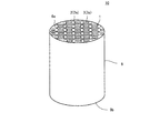
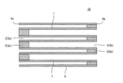
本発明のウォールフロー型排ガス浄化フィルタは、第1の端面から第2の端面まで貫通し流体の流路となる複数のセルを区画形成する多孔質の隔壁を有するハニカム構造部と、所定のセルの第1の端面と残余のセルの第2の端面とに配設された目封止部と、を備えている。図1は、本発明のウォールフロー型排ガス浄化フィルタの一実施形態を示す模式的斜視図である。また図2は、本発明のウォールフロー型排ガス浄化フィルタの一実施形態を示す模式的断面図であり、図3及び図4に示すA−A’方向における断面を示す図である。図1及び図2に示す通り、本発明のウォールフロー型排ガス浄化フィルタ10は、ハニカム構造部9及び目封止部3を備え、複数のセル2は、流体の流入側端面6aにおいて開口するとともに流体の流出側端面6bにおいて流出側目封止部3bが配設された入口開口セル2aと、流入側端面6aにおいて流入側目封止部3aが配設されるとともに流出側端面6bにおいて開口した出口開口セル2bと、からなる。
A wall flow type exhaust gas purification filter according to the present invention includes a honeycomb structure portion having porous partition walls that form a plurality of cells that penetrate from the first end face to the second end face and serve as fluid flow paths, and predetermined cells. And a plugging portion disposed on the second end surface of the remaining cells. FIG. 1 is a schematic perspective view showing an embodiment of a wall flow type exhaust gas purification filter of the present invention. FIG. 2 is a schematic cross-sectional view showing an embodiment of the wall flow type exhaust gas purification filter of the present invention, and is a view showing a cross section in the A-A ′ direction shown in FIGS. 3 and 4. As shown in FIGS. 1 and 2, the wall flow type exhaust
本発明において、ハニカム構造部9を構成する材料に特に制限はないが、強度、耐熱性、耐久性等の観点から、主成分は酸化物又は非酸化物の各種セラミックスや金属等であることが好ましい。具体的には例えばコージェライト、ムライト、アルミナ、スピネル、炭化珪素、窒化珪素、及びチタン酸アルミニウム等が考えられ、金属としてはFe−Cr−Al系金属及び金属珪素等が考えられる。これらの材料の中から選ばれた1種又は2種以上を主成分とすることが好ましい。高強度、高耐熱性等の観点から、アルミナ、ムライト、チタン酸アルミニウム、コージェライト、炭化珪素、及び窒化珪素からなる群から選ばれた1種又は2種以上を主成分とすることが特に好ましい。また、高熱伝導率や高耐熱性等の観点からは、炭化珪素又は珪素−炭化珪素複合材料が特に適している。ここで、「主成分」とは、ハニカム構造部の50質量%以上、好ましくは70質量%以上、更に好ましくは80質量%以上を構成することを意味する。
In the present invention, the material constituting the
本発明においては、目封止部3の材料にも特に制限はないが、上述のハニカム構造部9の好適な材料として挙げた各種セラミックス及び金属等の中から選択された1種又は2種以上を含むことが好ましい。
In the present invention, the material of the plugging
本発明のウォールフロー型排ガス浄化フィルタ10は、複数のセグメントを一体化させたものや、スリットが形成されたものであってもよい。このようにして作製されたウォールフロー型排ガス浄化フィルタ10は、フィルタにかかる熱応力を分散させることができ、局所的な温度上昇によるクラックの発生を防止することができる。
The wall flow type exhaust
複数のハニカムセグメントを一体化させる場合の各セグメントの大きさや形状に制限はないが、各セグメントが大きすぎると、セグメント化によるクラック防止効果が十分に発揮されず、小さすぎると各セグメントの製造や接合による一体化が煩雑となり好ましくない。このようなハニカムセグメントの形状は特に限定されるものではなく、例えば、断面形状が四角形状、即ちセグメントが四角柱状であるものを基本形状とし、一体化した後のウォールフロー型排ガス浄化フィルタ10において、その外周形状を適宜選択、加工することができる。本発明のウォールフロー型排ガス浄化フィルタ10全体の形状に特に制限はなく、図1に示すような断面が円形状のものの他にも、例えば楕円形状、レーストラック形状、長円形状等の略円形状の他、四角形状、6角形状などの多角形状とすることもできる。
There is no restriction on the size and shape of each segment when integrating a plurality of honeycomb segments, but if each segment is too large, the effect of preventing cracking due to segmentation will not be sufficiently exhibited, and if it is too small, the production of each segment Integration by joining becomes complicated and is not preferable. The shape of such a honeycomb segment is not particularly limited. For example, in the wall flow type exhaust
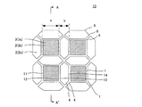
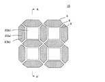
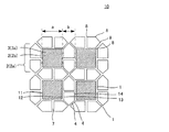
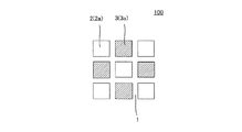
図3は、本発明のウォールフロー型排ガス浄化フィルタの一実施形態を流入側から見た模式的部分拡大図であり、図4は、本発明のウォールフロー型排ガス浄化フィルタの一実施形態を流出側から見た模式的部分拡大図である。図3及び図4に示す通り、本発明のウォールフロー型排ガス浄化フィルタ10において、入口開口セル2aは、ハニカム構造部9の中心軸方向に垂直な断面の形状が見かけ上略六角形であり、出口開口セル2bは、ハニカム構造部9の中心軸方向に垂直な断面の形状が略正方形となっている。図6は、従来のウォールフロー型排ガス浄化フィルタの一実施形態を示す模式的断面図である。図6に示す実施形態においては、入口開口セル2a及び出口開口セル2b(図6中の流入側目封じ部3aに相当)の断面形状がいずれも略正方形となっている。本発明のウォールフロー型排ガス浄化フィルタ10は、入口開口セル2aの断面形状を略六角形とすることによって、図6に示すような従来のウォールフロー型排ガス浄化フィルタ100と比較して、フィルタの濾過面積を大きくすることができ、PM堆積による圧力損失を低減することができる。ここで「断面形状」とは、セル2をその中心軸方向に垂直な平面で切断したときの、その断面に現れる形状のことであり、セル2を形成する隔壁1に囲まれた部分の形状を指す。また、本明細書においては、入口開口セル2aが複数の空間に分割されている場合であっても、隔壁1に囲まれた部分が略六角形である限り、分割された当該入口開口セル2aは「見かけ上」略六角形であるという。
FIG. 3 is a schematic partial enlarged view of an embodiment of the wall flow type exhaust gas purification filter of the present invention as viewed from the inflow side, and FIG. 4 is an outflow of one embodiment of the wall flow type exhaust gas purification filter of the present invention. It is the typical partial enlarged view seen from the side. As shown in FIGS. 3 and 4, in the wall flow type exhaust
また、図3及び図4に示す通り、本発明のウォールフロー型排ガス浄化フィルタ10において、複数のセル2は、所定の入口開口セル2aの1辺と、隣接する出口開口セル2bの1辺とが、略同一の長さを有するとともに略平行となるよう、1つの出口開口セル2bの周囲を4つの入口開口セル2aが取り囲む構造となっている。即ち、略正方形の断面形状を有する出口開口セル2bの4辺のそれぞれに対して、略六角形の断面形状を有する入口開口セル2aの1辺が隣接しており、隣接する辺同士は、略同一の長さを有するとともに略平行となっている。このような構造においては、出口開口セル2b同士が隣接することはなく、出口開口セル2bは、周囲すべてを4つの入口開口セル2aによって取り囲まれることになる。このような構造とすることによって、出口開口セル2bの開口率を大きくすると共に、出口開口セル2bの数を入口開口セル2aの数と比べて少なくできるため、初期の圧力損失を低減させることができる。
Moreover, as shown in FIG.3 and FIG.4, in the wall flow type exhaust
また、図3及び図4に示す通り、入口開口セル2aの6辺のうち、出口開口セル2bと略平行に隣接する2辺13,14を除く4辺4は、当該出口開口セル2bと隣接する別の出口開口セル2bの辺4とそれぞれ隣接している。即ち、入口開口セル2aにおける隣り合う2辺4の形成する頂点同士が4つ集合する部分においては、図3及び図4に示す通り、2つの隔壁1が互いに直交する構造となっている。このような構造とすることによって、隔壁1の熱容量を高く維持することができ、PMの堆積しやすい頂点部分におけるPM燃焼時の熱応力を緩和させることができる。
Moreover, as shown in FIG.3 and FIG.4, 4
出口開口セル2bの第1の辺11を形成する隔壁1と、出口開口セル2bの第1の辺11と対向する第2の辺12を形成する隔壁1との距離である距離aは、0.8mmを超え2.4mm未満の範囲であることが好ましい。ここで距離aとは、第1の辺11を形成する隔壁1の厚さ方向の中心から、対向する第2の辺12を形成する隔壁1の厚さ方向の中心とを結ぶ最短距離を指す。また、出口開口セル2bの1辺と略平行に隣接する入口開口セル2aの第3の辺13を形成する隔壁1と、入口開口セル2aの第3の辺13と対向する第4の辺14を形成する隔壁1との距離である距離bの、距離aに対する比率は、0.4を超え1.1未満の範囲であることが好ましい。ここで距離bとは、第3の辺13を形成する隔壁1の厚さ方向の中心から、対向する第4の辺14を形成する隔壁1の厚さ方向の中心とを結ぶ最短距離を指す。距離a及び距離bの関係を上記の範囲とすることによって、初期の圧力損失及びPM堆積時における圧力損失がバランス良く低減されるため好ましい。
The distance a that is the distance between the
本発明のウォールフロー型排ガス浄化フィルタ10の製造方法に特に制限はないが、例えば以下のような方法により製造することができる。ハニカム構造部9の原料粉末として、前述の好適な材料の中から選ばれた材料、例えば炭化珪素粉末を使用し、これにバインダ、例えばメチルセルロース及びヒドロキシプロポキシルメチルセルロース等を添加し、更に界面活性剤及び水を添加し、可塑性の坏土を作製する。この坏土を押出成形することにより、上述のような所定の断面形状の隔壁1及びセル2を有するハニカム構造部9の成形体を得る。これを、例えばマイクロ波及び熱風で乾燥後、ハニカム構造部9の製造に用いた材料と同様の材料で目封止することで目封止部3を配設し、更に乾燥した後、例えば窒素雰囲気中で加熱脱脂し、その後アルゴン等の不活性雰囲気中で焼成することにより本発明のウォールフロー型排ガス浄化フィルタ10を得ることができる。焼成温度及び焼成雰囲気は原料により異なり、当業者であれば、選択された材料に最適な焼成温度及び焼成雰囲気を選択することができる。
Although there is no restriction | limiting in particular in the manufacturing method of the wall flow type exhaust
本発明のウォールフロー型排ガス浄化フィルタ10を複数のハニカムセグメントが一体化された構成とするには、例えば以下のような方法がある。複数のハニカムセグメントを、例えばセラミックスセメントを用いて互いに接合し、乾燥硬化させた後、所望の形状となるよう外周を加工することによって、セグメント一体型のウォールフロー型排ガス浄化フィルタ10を得ることができる。
In order to make the wall flow type exhaust
図5は、本発明のウォールフロー型排ガス浄化フィルタの他の実施形態を流入側から見た模式的部分拡大図である。図5に示す通り、本発明のウォールフロー型排ガス浄化フィルタ10では、入口開口セル2aを中心軸方向に分割する分割壁7が形成されていてもよい。このような分割壁7を形成することによって、入口開口セル2aにおける濾過面積を大きくすることができる。分割壁7の形状や数、形成位置等は特に限定されるものではないが、図5に示す実施形態の様に、入口開口セル2aにおいて、第3の辺13の中央部と第4の辺14の中央部とを入口開口セル2aの中心軸方向に垂直な方向に結ぶよう分割壁7が形成されていることが好ましい。このような実施形態における入口開口セル2aは、分割壁7によって、実質的に、略五角形の断面形状を有する2つの空間に分割されることになる。
FIG. 5 is a schematic partially enlarged view of another embodiment of the wall flow type exhaust gas purification filter of the present invention as viewed from the inflow side. As shown in FIG. 5, in the wall flow type exhaust
分割壁7の材料は特に限定されるものではなく、濾過能を有する多孔質材料の中から適宜好適なものを選択することができるが、フィルタ作製時の容易性を鑑み、隔壁1と同じ材料を採用することが好ましい。また、分割壁7の厚さについても、特に限定されるものではないが、熱容量及び強度の観点から0.1〜0.5mmの範囲であることが好ましい。0.1mmよりも小さいと、熱容量及び強度の観点から好ましくない。また、0.5mmよりも大きいと、濾過面積確保の観点から好ましくない。なお、本明細書においては、分割壁7が形成されている場合であっても、入口開口セル2aは「見かけ上」略六角形であるとみなす。
The material of the dividing
本発明のウォールフロー型排ガス浄化フィルタ10では、入口開口セル2aにおいて、幾何学的表面積GSA(入口開口セル2aの全内表面積(S)をハニカム構造部9の全容積(V)で除した値(S/V)が、10〜30cm2/cm3であることが好ましく、12〜18cm2/cm3であることが更に好ましい。一般に、フィルタの濾過面積が大きいほど、隔壁へのPM堆積厚さを低減できるため圧力損失を低く抑えることができる。よって、入口開口セル2aの幾何学的表面積GSAが10cm2/cm3より小さいと、PM堆積時の圧力損失の増加につながるため好ましくない。また、30cm2/cm3より大きいと、初期の圧力損失が増加するため好ましくない。
In the wall flow type exhaust
本発明のウォールフロー型排ガス浄化フィルタ10では、入口開口セル2aのセル断面開口率が20〜70%であることが好ましく、25〜65%であることが更に好ましい。入口開口セル2aのセル断面開口率が20%より小さいと、初期の圧力損失が増加するため好ましくない。また、70%より大きいと、濾過流速が速くなるためPMの捕集効率が低下し、更に隔壁1の強度が不足するため好ましくない。ここで、「入口開口セル2aのセル断面開口率」とは、ハニカム構造部9の中心軸方向に垂直な断面における、「ハニカム構造部9を形成する隔壁1全体の断面積」と「全てのセル2の断面積の総和」との合計に対する、「入口開口セル2aの断面積の総和」の比率を意味する。
In the wall flow type exhaust
本発明のウォールフロー型排ガス浄化フィルタ10では、複数のセル2のそれぞれの水力直径が0.5〜2.5mmであることが好ましく、0.8〜2.2mmであることが更に好ましい。複数のセル2のそれぞれの水力直径が0.5mmより小さいと、初期の圧力損失が増加するため好ましくない。また、2.5mmより大きいと、排ガスと隔壁1との接触面積が減少し、浄化効率が低下するため好ましくない。ここで、複数のセル2のそれぞれの水力直径とは、各セル2の断面積及び周長に基づき、4×(断面積)/(周長)によって計算される値である。セル2の断面積とは、ハニカム構造部9の中心軸方向に垂直な断面に現れるセルの形状(断面形状)の面積を指し、セルの周長とは、そのセルの断面形状の周囲の長さ(当該断面を囲む閉じた線の長さ)を指す。
In the wall flow type exhaust
初期の圧力損失、PM堆積時の圧力損失、及び捕集効率のトレードオフを鑑み、本発明のウォールフロー型排ガス浄化フィルタ10においては、入口開口セル2aの幾何学的表面積GSAが10〜30cm2/cm3であること、入口開口セル2aのセル断面開口率が20〜70%であること、及び複数のセル2のそれぞれの水力直径が0.5〜2.5mmであることを同時に満たすことが好ましい。また、入口開口セル2aの幾何学的表面積GSAが12〜18cm2/cm3であること、入口開口セル2aのセル断面開口率が25〜65%であること、及び複数のセル2のそれぞれの水力直径が0.8〜2.2mmであること、を同時に満たすことが更に好ましい。
In view of the trade-off between the initial pressure loss, the pressure loss during PM deposition, and the collection efficiency, in the wall flow type exhaust
複数のセル2の、ハニカム構造部9の中心軸方向に垂直な断面における角部8、即ち、入口開口セル2aの略六角形の断面形状における6つの角、及び、出口開口セル2bの略正方形の断面形状における4つの角を形成する部分は、Rを有する湾曲形状であることが好ましい。具体的には、角部8は、曲率半径0.05〜0.4mmの湾曲形状であることが好ましく、応力集中防止の観点から、曲率半径0.2〜0.4mmの湾曲形状であることが更に好ましい。角部8の曲率半径が0.05mmよりも小さいと、角部8にPMが堆積しやすくなると同時に、隔壁1の熱応力及び強度が低下するため、熱応力緩和効果を十分に奏することができず好ましくない。また、角部8の曲率半径が0.4mmよりも大きいと、セルの濾過面積が減少するため好ましくない。
The
本発明のウォールフロー型排ガス浄化フィルタ10においては、複数のセル2を形成する隔壁1に触媒が担持されていてもよい。隔壁1に触媒を担持するとは、隔壁1の表面及び隔壁1に形成された細孔の内壁に、触媒がコーティングされることをいう。触媒の種類としては、SCR触媒(ゼオライト、チタニア、バナジウム)や、Pt、Rh、Pdのうち少なくとも2種の貴金属と、アルミナ、セリア、ジルコニアの少なくとも1種を含む三元触媒等が挙げられる。このような触媒を担持することにより、直接噴射式ガソリンエンジンやディーゼルエンジン等から排出される排ガスに含まれるNOx、CO、HC等を無毒化するとともに、隔壁1の表面に堆積したPMを触媒作用により燃焼除去させ易くすることが可能となる。
In the wall flow type exhaust
本発明のウォールフロー型排ガス浄化フィルタ10に上記のような触媒を担持させる方法は、特に限定されず、当業者が通常行う方法を採用することができる。具体的には、触媒スラリーをウォッシュコートして乾燥、焼成する方法等が挙げられる。
The method for supporting the catalyst as described above on the wall flow type exhaust
以下、本発明を実施例によりさらに具体的に説明するが、本発明はこれらの実施例に限定されるものではない。 EXAMPLES Hereinafter, the present invention will be described more specifically with reference to examples, but the present invention is not limited to these examples.
(実施例1)
セラミック原料として、炭化珪素(SiC)粉末と金属珪素(Si)粉末とを80:20の質量割合で混合したものを準備した。この混合原料に、バインダとしてヒドロキシプロピルメチルセルロース、造孔材として吸水性樹脂を添加するとともに、水を添加して成形原料を作製した。得られた成形原料を、ニーダーを用いて混練し、坏土を得た。
Example 1
A ceramic raw material prepared by mixing silicon carbide (SiC) powder and metal silicon (Si) powder in a mass ratio of 80:20 was prepared. To this mixed raw material, hydroxypropylmethylcellulose as a binder and a water-absorbing resin as a pore former were added, and water was added to prepare a molding raw material. The obtained forming raw material was kneaded using a kneader to obtain a clay.
次に、得られた坏土を、真空押出成形機を用いて成形し、図3及び図4に示すセル断面構造を有する四角柱形状のハニカムセグメントを16個作製した。ハニカムセグメントの断面を36mm×36mmとし、長さを152mmとした。また、図3に示す距離aを2.2mm、距離bを1.76mmとし、隔壁厚さを0.2mmとした。
とした。
Next, the obtained kneaded material was molded using a vacuum extrusion molding machine, and 16 rectangular column-shaped honeycomb segments having a cell cross-sectional structure shown in FIGS. 3 and 4 were produced. The cross section of the honeycomb segment was 36 mm × 36 mm and the length was 152 mm. Further, the distance a shown in FIG. 3 was 2.2 mm, the distance b was 1.76 mm, and the partition wall thickness was 0.2 mm.
It was.
続いて、得られたハニカムセグメントを高周波誘電加熱乾燥した後、熱風乾燥機を用いて120℃で2時間乾燥した。なお、乾燥時には、ハニカムセグメントの流出側端面6bが、鉛直下向きになるように配置して乾燥を行った。
Subsequently, the obtained honeycomb segment was dried by high-frequency dielectric heating, and then dried at 120 ° C. for 2 hours using a hot air dryer. In addition, at the time of drying, it arrange | positioned so that the outflow
乾燥後のハニカムセグメントに、目封止部3を形成した。まず、ハニカムセグメントの流入側端面6aにマスクを施し、マスクの施された端部(流入側端部)を目封止スラリーに浸漬して、マスクが施されていないセル2(入口開口セル2a)の開口部に目封止スラリーを充填し、目封止部3(流入側目封止部3a)を形成した。そして、乾燥後のハニカムセグメントの流出側端面6bについても同様にして、残余のセル(即ち、流入側端面6aにおいて目封止されていないセル2(出口開口セル2b))にも目封じ部3(流出側目封止部3b)を形成した。
Plugged
そして、目封止部3の形成されたハニカムセグメントを脱脂、焼成し、目封止ハニカムセグメントを得た。脱脂の条件は、550℃で3時間とし、焼成の条件は、アルゴン雰囲気下で、1450℃、2時間とした。なお、焼成時には、ハニカムセグメントの流出側端面6bが、鉛直下向きになるように配置して焼成を行った。
And the honeycomb segment in which the plugging
16個の焼成済のハニカムセグメントを、接合材(セラミックスセメント)を用いて接合し一体化した。接合材は、無機粒子、無機接着剤を主成分とし、副成分として、有機バインダ、界面活性剤、発泡樹脂、水等を含むよう構成した。無機粒子としては、板状粒子、無機接着剤としては、コロイダルシリカ(シリカゾル)を使用した。板状粒子としては、マイカを使用した。16個のハニカムセグメントが一体化に接合されたハニカムセグメント接合体の外周を円筒状に研削加工し、その外周面にコート材を塗布して、完成体を得た。コート材は、セラミックス粉末、水、結合材を含むよう構成した。 Sixteen fired honeycomb segments were joined and integrated using a joining material (ceramic cement). The bonding material was composed mainly of inorganic particles and an inorganic adhesive, and contained an organic binder, a surfactant, a foamed resin, water and the like as subcomponents. Plate-like particles were used as the inorganic particles, and colloidal silica (silica sol) was used as the inorganic adhesive. Mica was used as the plate-like particles. The outer periphery of the joined honeycomb segment assembly in which the 16 honeycomb segments were integrally joined was ground into a cylindrical shape, and a coating material was applied to the outer circumferential surface to obtain a finished product. The coating material was configured to include ceramic powder, water, and a binder.
上記の工程によって、図3及び図4に示すセル断面構造を有する実施例1のウォールフロー型排ガス浄化フィルタ10を作製した。
Through the above steps, the wall flow type exhaust
(実施例2〜24、比較例1〜4)
距離a、距離b、及び隔壁厚さを表1に示す通りとしたほかは、実施例1と同様にして、実施例2〜24及び比較例1〜4のウォールフロー型排ガス浄化フィルタ10を作製した。
(Examples 2 to 24, Comparative Examples 1 to 4)
A wall flow type exhaust
(比較例5〜8)
押出成型時の口金の形状を変更したほかは、実施例1と同様の工程によって、図6に示すセル断面構造を有する比較例5〜8のウォールフロー型排ガス浄化フィルタ100を作製した。セルピッチ及び隔壁厚さをそれぞれ表1に示す通りとした。ここでセルピッチとは、略正方形の断面形状を有するセル2の対向する2辺間の距離に隔壁厚さを加えた長さのことである。
(Comparative Examples 5 to 8)
A wall flow type exhaust
実施例1〜24及び比較例1〜8のウォールフロー型排ガス浄化フィルタをディーゼルエンジンの排気管に取り付け、初期の圧力損失、PM堆積時の圧力損失、及びクラック限界を測定し、評価を行った。結果を表1に示した。 The wall flow type exhaust gas purification filters of Examples 1 to 24 and Comparative Examples 1 to 8 were attached to the exhaust pipe of a diesel engine, and the initial pressure loss, the pressure loss during PM deposition, and the crack limit were measured and evaluated. . The results are shown in Table 1.
(初期圧損測定方法)
フィルタに200℃の空気を2.4Nm3/minで流して、流入側と流出側とにおける圧力差から、初期の圧力損失(初期圧損)を測定した。初期圧損が、2.1kPa以上を不可、1.9kPa以上2.1kPa未満を可、1.7kPa以上1.9kPa未満を良、1.7kPa未満を優秀とした。
(Initial pressure loss measurement method)
Air at 200 ° C. was passed through the filter at 2.4 Nm 3 / min, and the initial pressure loss (initial pressure loss) was measured from the pressure difference between the inflow side and the outflow side. An initial pressure loss of 2.1 kPa or more is impossible, 1.9 kPa or more and less than 2.1 kPa is acceptable, 1.7 kPa or more and less than 1.9 kPa is good, and less than 1.7 kPa is considered excellent.
(PM堆積時圧損測定方法)
軽油を酸素欠如状態で燃焼させることでススを発生させ、スス発生量10g/h、流量2.4Nm3/min、温度200℃の燃焼ガスに希釈空気を追加して調整を行ったスス含有燃焼ガスをフィルタに流し、フィルタへのスス堆積量が4g/Lとなった際の流入側と流出側とにおける圧力差から、PM堆積時における圧力損失(PM堆積時圧損)を測定した。PM堆積時圧損が、6.9kPa以上を不可、6.5kPa以上6.9kPa未満を可、6.3kPa以上6.5kPa未満を良、6.3kPa未満を優秀とした。
(Method of measuring pressure loss during PM deposition)
Soot is generated by burning light oil in the absence of oxygen, and soot-containing combustion is adjusted by adding diluted air to the combustion gas of soot generation amount 10g / h, flow rate 2.4Nm 3 / min, temperature 200 ° C Gas was passed through the filter, and pressure loss during PM deposition (pressure loss during PM deposition) was measured from the pressure difference between the inflow side and the outflow side when the amount of soot deposition on the filter reached 4 g / L. The pressure loss during PM deposition was 6.9 kPa or more, 6.5 kPa or more and less than 6.9 kPa, 6.3 kPa or more and less than 6.5 kPa was good, and 6.3 kPa or less was considered excellent.
(クラック限界測定方法)
フィルタを排気量2リッターの乗用車用ディーゼルエンジンの排気系に搭載し、フィルタにススを堆積させた。次いで、排気ガス温度を650℃まで上昇させた後、アイドリング運転に条件変更してガス流量を急激に減らす条件でスス再生を行った。スス堆積量を変化させてこの試験を繰り返し、フィルタにクラックが発生する最小スス堆積量を調査した。このスス堆積量をクラック限界と定義して、クラック限界を測定した。クラック限界が、8g/L未満を不可、8g/L以上9g/L未満を可、9g/L以上10g/L未満を良、10g/L以上を優秀とした。
(Crack limit measurement method)
The filter was installed in the exhaust system of a 2-liter passenger car diesel engine, and soot was deposited on the filter. Next, after raising the exhaust gas temperature to 650 ° C., the condition was changed to idling operation, and soot regeneration was performed under the condition of rapidly reducing the gas flow rate. This test was repeated while changing the soot deposition amount, and the minimum soot deposition amount at which cracks occurred in the filter was investigated. The soot accumulation amount was defined as the crack limit, and the crack limit was measured. A crack limit of less than 8 g / L was impossible, 8 g / L or more and less than 9 g / L was acceptable, 9 g / L or more and less than 10 g / L was good, and 10 g / L or more was considered excellent.
(実施例25)
押出成型時の口金の形状を変更したほかは、実施例1と同様の工程によって、図5に示すセル断面構造を有する実施例25のウォールフロー型排ガス浄化フィルタ10を作製した。図5に示す距離aを2.2mm、距離bを1.76mmとし、隔壁厚さを0.2mmとした。また、分割壁の厚さを0.15mmとした。
(Example 25)
A wall flow type exhaust
(実施例26〜51、比較例9〜15)
距離a、距離b、及び隔壁厚さを表2に示す通りとしたほかは、実施例25と同様にして、実施例26〜51及び比較例9〜15のウォールフロー型排ガス浄化フィルタ10を作製した。
(Examples 26 to 51, Comparative Examples 9 to 15)
A wall flow type exhaust
実施例25〜51及び比較例9〜15のウォールフロー型排ガス浄化フィルタ10をディーゼルエンジンの排気管に取り付け、初期の圧力損失及びPM堆積時の圧力損失を測定し、評価を行った。結果を表2に示した。 The wall flow type exhaust gas purification filters 10 of Examples 25 to 51 and Comparative Examples 9 to 15 were attached to the exhaust pipe of a diesel engine, and the initial pressure loss and the pressure loss during PM deposition were measured and evaluated. The results are shown in Table 2.

(考察)
表1及び表2の結果から、すべてのセルの断面形状が略正方形である従来のフィルタと比較して、図3及び4に示すセル断面構造を有する本発明のフィルタは、初期圧損、PM堆積時の圧損、及びクラック限界のいずれにおいても良好な結果を示すことが分かった。また、図3及び図5に示す距離aが0.8mmを超え2.4mm未満の範囲にあり、且つ距離b/距離aの値が0.4を超え1.1未満の範囲にある場合は、そうでない場合と比較して、初期圧損及びPM堆積時の圧損のいずれにおいても有意な効果を奏することが分かった。
(Discussion)
From the results of Tables 1 and 2, the filter of the present invention having the cell cross-sectional structure shown in FIGS. 3 and 4 has an initial pressure loss and PM deposition compared with the conventional filter in which the cross-sectional shape of all the cells is substantially square. It was found that good results were obtained both in terms of time pressure loss and crack limit. In addition, when the distance a shown in FIGS. 3 and 5 is in the range of more than 0.8 mm and less than 2.4 mm, and the value of distance b / distance a is in the range of more than 0.4 and less than 1.1 As compared with the case where it is not so, it turned out that there exists a significant effect in both the initial pressure loss and the pressure loss at the time of PM deposition.
本発明に係るウォールフロー型排ガス浄化フィルタは、直噴ガソリンエンジンやディーゼルエンジン等から排出される排ガスに含まれる微粒子および有害ガス成分の浄化に用いられるDPFとして好適に使用することができる。 The wall flow type exhaust gas purification filter according to the present invention can be suitably used as a DPF used for purification of fine particles and harmful gas components contained in exhaust gas discharged from a direct injection gasoline engine, a diesel engine or the like.
1:隔壁、2:セル、2a:入口開口セル、2b:出口開口セル、3:目封止部、3a:流入側目封止部、3b:流出側目封止部、4:辺、6a:流入側端面、6b:流出側端面、7:分割壁、8:角部、9:ハニカム構造部、10,100:ウォールフロー型排ガス浄化フィルタ、11:第1の辺、12:第2の辺、13:第3の辺、14:第4の辺、a:距離a、b:距離b。 1: partition, 2: cell, 2a: inlet opening cell, 2b: outlet opening cell, 3: plugging portion, 3a: inflow side plugging portion, 3b: outflow side plugging portion, 4: side, 6a : Inflow side end surface, 6b: Outflow side end surface, 7: Partition wall, 8: Corner portion, 9: Honeycomb structure portion, 10, 100: Wall flow type exhaust gas purification filter, 11: First side, 12: Second Side: 13: Third side, 14: Fourth side, a: Distance a, b: Distance b.
[4] 前記入口開口セルにおいて、幾何学的表面積GSA(前記入口開口セルの全内表面積(S)を前記ハニカム構造部の全容積(V)で除した値(S/V))が、12〜18cm2/cm3であり、前記入口開口セルのセル断面開口率が25〜65%であり、複数の前記セルのそれぞれの水力直径が0.8〜2.2mmである、前記[1]〜[3]のいずれかに記載のウォールフロー型排ガス浄化フィルタ。 [4] In the inlet opening cell, the geometric surface area GSA (value (S / V) obtained by dividing the total inner surface area (S) of the inlet opening cell by the total volume (V) of the honeycomb structure portion) is 12 a ~18cm 2 / cm 3, the cell open frontal area of the inlet opening cells is 25 to 65% respectively of the hydraulic diameter of the plurality of cells is 0.8~2.2Mm, wherein [1] Wall flow type exhaust gas purification filter in any one of-[3].
また、図3及び図4に示す通り、入口開口セル2aの6辺のうち、出口開口セル2bと略平行に隣接する2辺13,14を除く4辺4は、当該入口開口セル2aと隣接する別の入口開口セル2aの辺4とそれぞれ隣接している。即ち、入口開口セル2aにおける隣り合う2辺4の形成する頂点同士が4つ集合する部分においては、図3及び図4に示す通り、2つの隔壁1が互いに直交する構造となっている。このような構造とすることによって、隔壁1の熱容量を高く維持することができ、PMの堆積しやすい頂点部分におけるPM燃焼時の熱応力を緩和させることができる。
Further, as shown in FIGS. 3 and 4, of the six sides of the
次に、得られた坏土を、真空押出成形機を用いて成形し、図3及び図4に示すセル断面構造を有する四角柱形状のハニカムセグメントを16個作製した。ハニカムセグメントの断面を36mm×36mmとし、長さを152mmとした。また、図3に示す距離aを2.2mm、距離bを1.76mmとし、隔壁厚さを0.2mmとした。 Next, the obtained kneaded material was molded using a vacuum extrusion molding machine, and 16 rectangular column-shaped honeycomb segments having a cell cross-sectional structure shown in FIGS. 3 and 4 were produced. The cross section of the honeycomb segment was 36 mm × 36 mm and the length was 152 mm. Further, the distance a shown in FIG. 3 was 2.2 mm, the distance b was 1.76 mm, and the partition wall thickness was 0.2 mm .
Claims (6)
所定の前記セルの前記第1の端面と残余の前記セルの前記第2の端面とに配設された目封止部と、を備え、
複数の前記セルは、前記流体の流入側端面において開口するとともに前記流体の流出側端面において流出側目封止部が配設された入口開口セルと、前記流入側端面において流入側目封止部が配設されるとともに前記流出側端面において開口した出口開口セルと、からなり、
前記入口開口セルは、前記ハニカム構造部の中心軸方向に垂直な断面の形状が見かけ上略六角形であり、
前記出口開口セルは、前記ハニカム構造部の中心軸方向に垂直な断面の形状が略正方形であり、
複数の前記セルは、所定の前記入口開口セルの1辺と、隣接する前記出口開口セルの1辺とが、略同一の長さを有するとともに略平行となるよう、1つの前記出口開口セルの周囲を4つの前記入口開口セルが取り囲む構造となっており、
前記出口開口セルの第1の辺を形成する前記隔壁と、前記出口開口セルの前記第1の辺と対向する第2の辺を形成する前記隔壁との距離である距離aは、0.8mmを超え2.4mm未満の範囲であり、
前記出口開口セルの1辺と略平行に隣接する前記入口開口セルの第3の辺を形成する前記隔壁と、前記入口開口セルの前記第3の辺と対向する第4の辺を形成する前記隔壁との距離である距離bの、前記距離aに対する比率は、0.4を超え1.1未満の範囲である、ウォールフロー型排ガス浄化フィルタ。 A honeycomb structure having a porous partition wall penetrating from the first end surface to the second end surface and defining a plurality of cells serving as fluid flow paths;
A plugging portion disposed on the first end face of the predetermined cell and the second end face of the remaining cell, and
The plurality of cells are open at the inflow end surface of the fluid and have an outflow side plugged portion disposed at the outflow side end surface of the fluid, and an inflow side plugged portion at the inflow side end surface And an outlet opening cell opened at the outflow side end face, and
The inlet opening cell is apparently substantially hexagonal in cross-sectional shape perpendicular to the central axis direction of the honeycomb structure part,
The outlet opening cell has a substantially square cross-sectional shape perpendicular to the central axis direction of the honeycomb structure part,
The plurality of cells have one outlet opening cell such that one side of the predetermined inlet opening cell and one side of the adjacent outlet opening cell have substantially the same length and are substantially parallel to each other. It has a structure that surrounds the four entrance opening cells,
A distance a which is a distance between the partition wall forming the first side of the outlet opening cell and the partition wall forming the second side facing the first side of the outlet opening cell is 0.8 mm. And less than 2.4 mm,
The partition that forms the third side of the inlet opening cell adjacent to and substantially parallel to one side of the outlet opening cell, and the fourth side that faces the third side of the inlet opening cell The wall flow type exhaust gas purification filter, wherein the ratio of the distance b, which is the distance to the partition wall, to the distance a is in the range of more than 0.4 and less than 1.1.
前記入口開口セルのセル断面開口率が20〜70%であり、
複数の前記セルのそれぞれの水力直径が0.5〜2.5mmである、請求項1又は2に記載のウォールフロー型排ガス浄化フィルタ。 In the inlet opening cell, the geometric surface area GSA (the value (S / V) obtained by dividing the total inner surface area (S) of the inlet opening cell by the total volume (V) of the honeycomb structure portion) is 10 to 30 cm 2. / Cm 3 ,
The cell opening ratio of the inlet opening cell is 20 to 70%,
The wall flow type exhaust gas purification filter according to claim 1 or 2, wherein each of the plurality of cells has a hydraulic diameter of 0.5 to 2.5 mm.
前記入口開口セルのセル断面開口率が25〜65%であり、
複数の前記セルのそれぞれの水力直径が0.8〜2.2mmである、請求項1〜3のいずれか1項に記載のウォールフロー型排ガス浄化フィルタ。 In the inlet opening cell, the geometric surface area GSA (the value (S / V) obtained by dividing the total inner surface area (S) excluding the pores of the inlet opening cell by the total volume (V) of the honeycomb structure portion)) 12-18 cm 2 / cm 3 ,
The cell opening ratio of the inlet opening cell is 25 to 65%,
The wall flow type exhaust gas purification filter according to any one of claims 1 to 3, wherein a hydraulic diameter of each of the plurality of cells is 0.8 to 2.2 mm.
Priority Applications (4)
| Application Number | Priority Date | Filing Date | Title |
|---|---|---|---|
| JP2013078981A JP6140509B2 (en) | 2013-04-04 | 2013-04-04 | Wall flow type exhaust gas purification filter |
| US14/228,810 US9080484B2 (en) | 2013-04-04 | 2014-03-28 | Wall flow type exhaust gas purification filter |
| DE102014004712.1A DE102014004712B4 (en) | 2013-04-04 | 2014-04-01 | Wall flow type exhaust gas purification filter |
| US29/524,329 USD763427S1 (en) | 2013-04-04 | 2015-04-20 | Wall flow type exhaust gas purification filter |
Applications Claiming Priority (1)
| Application Number | Priority Date | Filing Date | Title |
|---|---|---|---|
| JP2013078981A JP6140509B2 (en) | 2013-04-04 | 2013-04-04 | Wall flow type exhaust gas purification filter |
Publications (2)
| Publication Number | Publication Date |
|---|---|
| JP2014200741A true JP2014200741A (en) | 2014-10-27 |
| JP6140509B2 JP6140509B2 (en) | 2017-05-31 |
Family
ID=51653501
Family Applications (1)
| Application Number | Title | Priority Date | Filing Date |
|---|---|---|---|
| JP2013078981A Active JP6140509B2 (en) | 2013-04-04 | 2013-04-04 | Wall flow type exhaust gas purification filter |
Country Status (3)
| Country | Link |
|---|---|
| US (2) | US9080484B2 (en) |
| JP (1) | JP6140509B2 (en) |
| DE (1) | DE102014004712B4 (en) |
Cited By (24)
| Publication number | Priority date | Publication date | Assignee | Title |
|---|---|---|---|---|
| DE102016002709A1 (en) | 2015-03-13 | 2016-09-15 | Ngk Insulators, Ltd. | honeycomb structure |
| DE102016007190A1 (en) | 2015-07-17 | 2017-01-19 | Ngk Insulators, Ltd. | honeycombs |
| DE102016010606A1 (en) | 2015-09-02 | 2017-03-02 | Ngk Insulators, Ltd. | Locked honeycomb structure and closed honeycomb segment |
| DE102016010596A1 (en) | 2015-09-02 | 2017-03-02 | Ngk Insulators, Ltd. | Locked honeycomb structure and closed honeycomb segment |
| DE102016010594A1 (en) | 2015-09-02 | 2017-03-02 | Ngk Insulators, Ltd. | Locked honeycomb structure and closed honeycomb segment |
| DE102016010598A1 (en) | 2015-09-04 | 2017-03-09 | Ngk Insulators, Ltd. | Apparatus for treating exhaust gas, method for increasing the temperature of a catalyst, method for regenerating a honeycomb structure and method for removing ash |
| DE102016013084A1 (en) | 2015-11-11 | 2017-05-11 | Ngk Insulators, Ltd. | Locked honeycomb structure |
| JP2017089617A (en) * | 2015-11-11 | 2017-05-25 | 日本碍子株式会社 | Plugged Honeycomb Structure |
| JP2017170323A (en) * | 2016-03-23 | 2017-09-28 | 日本碍子株式会社 | Honeycomb filter |
| JP2017170322A (en) * | 2016-03-23 | 2017-09-28 | 日本碍子株式会社 | Honeycomb filter |
| DE102017003047A1 (en) | 2016-03-30 | 2017-10-05 | Ngk Insulators, Ltd. | Locked honeycomb structure |
| JP2017185484A (en) * | 2016-03-30 | 2017-10-12 | 日本碍子株式会社 | Plugged Honeycomb Structure |
| DE102017008767A1 (en) | 2016-10-11 | 2018-04-12 | Ngk Insulators, Ltd. | Locked honeycomb structure |
| DE102017008765A1 (en) | 2016-10-11 | 2018-04-12 | Ngk Insulators, Ltd. | Locked honeycomb structure |
| JP2018065091A (en) * | 2016-10-19 | 2018-04-26 | 日本碍子株式会社 | Plugged Honeycomb Structure |
| DE102018204933A1 (en) | 2017-03-30 | 2018-10-04 | Ngk Insulators, Ltd. | honeycombs |
| DE102018204932A1 (en) | 2017-03-30 | 2018-10-18 | Ngk Insulators, Ltd. | honeycombs |
| DE102014004712B4 (en) | 2013-04-04 | 2019-04-18 | Ngk Insulators, Ltd. | Wall flow type exhaust gas purification filter |
| USD849914S1 (en) | 2015-05-13 | 2019-05-28 | Ngk Insulators, Ltd. | Filter segment for removing particle matter |
| US10300424B2 (en) | 2014-07-23 | 2019-05-28 | Ibiden Co., Ltd. | Honeycomb filter |
| US10335727B2 (en) * | 2014-07-23 | 2019-07-02 | Ibiden Co., Ltd. | Honeycomb filter |
| WO2019187126A1 (en) * | 2018-03-30 | 2019-10-03 | 日本碍子株式会社 | Plugged honeycomb segment, and plugged honeycomb structure |
| JP2019177368A (en) * | 2018-03-30 | 2019-10-17 | 日本碍子株式会社 | Plugged honeycomb segment and plugged honeycomb structure |
| US10918988B2 (en) | 2018-09-27 | 2021-02-16 | Ngk Insulators, Ltd. | Honeycomb filter |
Families Citing this family (19)
| Publication number | Priority date | Publication date | Assignee | Title |
|---|---|---|---|---|
| WO2013186923A1 (en) | 2012-06-15 | 2013-12-19 | イビデン株式会社 | Honeycomb filter |
| WO2013186922A1 (en) | 2012-06-15 | 2013-12-19 | イビデン株式会社 | Honeycomb filter |
| WO2014054159A1 (en) | 2012-10-04 | 2014-04-10 | イビデン株式会社 | Honeycomb filter |
| JP6239305B2 (en) | 2013-07-31 | 2017-11-29 | イビデン株式会社 | Honeycomb filter |
| JP6239306B2 (en) * | 2013-07-31 | 2017-11-29 | イビデン株式会社 | Honeycomb filter |
| JP6239307B2 (en) | 2013-07-31 | 2017-11-29 | イビデン株式会社 | Honeycomb filter |
| JP6239303B2 (en) | 2013-07-31 | 2017-11-29 | イビデン株式会社 | Honeycomb filter |
| JP6239304B2 (en) | 2013-07-31 | 2017-11-29 | イビデン株式会社 | Honeycomb filter |
| USD763429S1 (en) | 2015-02-24 | 2016-08-09 | Ngk Insulators, Ltd. | Filter for removing particle matter |
| JP6934702B2 (en) * | 2015-03-27 | 2021-09-15 | 株式会社デンソー | Exhaust gas purification filter |
| JP6767235B2 (en) * | 2016-10-19 | 2020-10-14 | 日本碍子株式会社 | Sealed honeycomb structure |
| USD860748S1 (en) * | 2017-10-31 | 2019-09-24 | Lake Country Manufacturing, Inc. | Buffing pad with collapsed cell structure |
| JP7049156B2 (en) * | 2018-03-30 | 2022-04-06 | 日本碍子株式会社 | Honeycomb filter |
| US11975285B2 (en) * | 2018-11-15 | 2024-05-07 | Corning Incorporated | Tilted cell honeycomb body, extrusion die and method of manufacture thereof |
| CN113329806B (en) * | 2018-11-16 | 2022-12-02 | 康宁股份有限公司 | Honeycomb body having an array of through channels with a range of hydraulic diameters |
| WO2020202253A1 (en) | 2019-03-29 | 2020-10-08 | 本田技研工業株式会社 | Exhaust purification filter |
| JP7006662B2 (en) * | 2019-07-12 | 2022-01-24 | 株式会社デンソー | Exhaust gas purification filter |
| CN114746182B (en) | 2019-11-29 | 2025-04-25 | 三井金属矿业株式会社 | Catalysts for exhaust gas purification |
| USD1080807S1 (en) * | 2024-02-27 | 2025-06-24 | Jiangxi Acichemshun Industry Co., Ltd. | Catalyst carrier |
Citations (6)
| Publication number | Priority date | Publication date | Assignee | Title |
|---|---|---|---|---|
| JP2004000896A (en) * | 2002-03-25 | 2004-01-08 | Ngk Insulators Ltd | Honeycomb filter |
| JP2004084666A (en) * | 2002-08-23 | 2004-03-18 | Omg Ag & Co Kg | Removal of soot fine particles from exhaust gas of diesel engine |
| JP2007175571A (en) * | 2005-12-27 | 2007-07-12 | Denso Corp | Hex cell honeycomb structure |
| JP2009240864A (en) * | 2008-03-28 | 2009-10-22 | Ngk Insulators Ltd | Honeycomb structure and method for manufacturing the same |
| JP2012254441A (en) * | 2011-05-17 | 2012-12-27 | Sumitomo Chemical Co Ltd | Honeycomb filter |
| JP2013039514A (en) * | 2011-08-12 | 2013-02-28 | Sumitomo Chemical Co Ltd | Honeycomb structure |
Family Cites Families (24)
| Publication number | Priority date | Publication date | Assignee | Title |
|---|---|---|---|---|
| US4416676A (en) * | 1982-02-22 | 1983-11-22 | Corning Glass Works | Honeycomb filter and method of making it |
| US4417908A (en) * | 1982-02-22 | 1983-11-29 | Corning Glass Works | Honeycomb filter and method of making it |
| USD414281S (en) * | 1998-02-04 | 1999-09-21 | Hans Sassenberg | Plastic paver |
| CN1322909C (en) * | 2002-09-13 | 2007-06-27 | 揖斐电株式会社 | honeycomb structure |
| DE602004011997T2 (en) * | 2003-06-05 | 2009-02-26 | Ibiden Co., Ltd., Ogaki | HONEYCOMB BODY STRUCTURE |
| USD501566S1 (en) * | 2004-03-11 | 2005-02-01 | Building Materials Investment Corporation | Embossed single ply roofing membrane |
| JPWO2006126278A1 (en) | 2005-05-27 | 2008-12-25 | イビデン株式会社 | Honeycomb structure |
| USD548826S1 (en) * | 2005-12-15 | 2007-08-14 | Hks Co., Ltd. | Air cleaner for internal-combustion engine |
| EP2216084B1 (en) | 2007-11-28 | 2014-06-18 | NGK Insulators, Ltd. | Method for bonding plugged honeycomb structures |
| USD605189S1 (en) * | 2008-09-17 | 2009-12-01 | Pfu Limited | Computer terminal |
| JP2010227767A (en) | 2009-03-26 | 2010-10-14 | Ngk Insulators Ltd | Honeycomb filter |
| US8945698B2 (en) * | 2009-09-24 | 2015-02-03 | Ngk Insulators, Ltd. | Honeycomb structure and method for manufacturing the same |
| USD679792S1 (en) * | 2010-06-07 | 2013-04-09 | Matthew Hollingsworth | Scented air filter |
| JP5972257B2 (en) * | 2011-03-10 | 2016-08-17 | 日本碍子株式会社 | Honeycomb structure |
| JP5874283B2 (en) | 2011-10-03 | 2016-03-02 | スズキ株式会社 | Braking control device |
| USD744078S1 (en) * | 2011-12-07 | 2015-11-24 | Sumitomo Chemical Company, Limited | Particulate filter |
| JP6140509B2 (en) | 2013-04-04 | 2017-05-31 | 日本碍子株式会社 | Wall flow type exhaust gas purification filter |
| USD749714S1 (en) * | 2013-04-30 | 2016-02-16 | Ibiden Co., Ltd. | Honeycomb filter |
| USD748237S1 (en) * | 2013-04-30 | 2016-01-26 | Ibiden Co., Ltd | Honeycomb filter |
| USD738998S1 (en) * | 2013-05-27 | 2015-09-15 | Harlice Laver | Removable filter for a fan |
| USD740405S1 (en) * | 2013-07-17 | 2015-10-06 | Ngk Insulators, Ltd. | Catalyst carrier for gas purification |
| USD732650S1 (en) * | 2013-07-17 | 2015-06-23 | Ngk Insulators, Ltd. | Filter for removing particle matter |
| USD733277S1 (en) * | 2013-07-17 | 2015-06-30 | Ngk Insulators, Ltd. | Filter for removing particle matter |
| JP1515965S (en) * | 2014-02-21 | 2015-01-26 |
-
2013
- 2013-04-04 JP JP2013078981A patent/JP6140509B2/en active Active
-
2014
- 2014-03-28 US US14/228,810 patent/US9080484B2/en active Active
- 2014-04-01 DE DE102014004712.1A patent/DE102014004712B4/en active Active
-
2015
- 2015-04-20 US US29/524,329 patent/USD763427S1/en active Active
Patent Citations (6)
| Publication number | Priority date | Publication date | Assignee | Title |
|---|---|---|---|---|
| JP2004000896A (en) * | 2002-03-25 | 2004-01-08 | Ngk Insulators Ltd | Honeycomb filter |
| JP2004084666A (en) * | 2002-08-23 | 2004-03-18 | Omg Ag & Co Kg | Removal of soot fine particles from exhaust gas of diesel engine |
| JP2007175571A (en) * | 2005-12-27 | 2007-07-12 | Denso Corp | Hex cell honeycomb structure |
| JP2009240864A (en) * | 2008-03-28 | 2009-10-22 | Ngk Insulators Ltd | Honeycomb structure and method for manufacturing the same |
| JP2012254441A (en) * | 2011-05-17 | 2012-12-27 | Sumitomo Chemical Co Ltd | Honeycomb filter |
| JP2013039514A (en) * | 2011-08-12 | 2013-02-28 | Sumitomo Chemical Co Ltd | Honeycomb structure |
Cited By (52)
| Publication number | Priority date | Publication date | Assignee | Title |
|---|---|---|---|---|
| DE102014004712B4 (en) | 2013-04-04 | 2019-04-18 | Ngk Insulators, Ltd. | Wall flow type exhaust gas purification filter |
| US10335727B2 (en) * | 2014-07-23 | 2019-07-02 | Ibiden Co., Ltd. | Honeycomb filter |
| US10300424B2 (en) | 2014-07-23 | 2019-05-28 | Ibiden Co., Ltd. | Honeycomb filter |
| JP2016168561A (en) * | 2015-03-13 | 2016-09-23 | 日本碍子株式会社 | Honeycomb structure |
| US10105696B2 (en) | 2015-03-13 | 2018-10-23 | Ngk Insulators, Ltd. | Honeycomb structure |
| DE102016002709A1 (en) | 2015-03-13 | 2016-09-15 | Ngk Insulators, Ltd. | honeycomb structure |
| USD849914S1 (en) | 2015-05-13 | 2019-05-28 | Ngk Insulators, Ltd. | Filter segment for removing particle matter |
| USD851229S1 (en) | 2015-05-13 | 2019-06-11 | Ngk Insulators, Ltd. | Filter segment for removing particle matter |
| DE102016007190A1 (en) | 2015-07-17 | 2017-01-19 | Ngk Insulators, Ltd. | honeycombs |
| JP2017023919A (en) * | 2015-07-17 | 2017-02-02 | 日本碍子株式会社 | Honeycomb filter |
| US9957861B2 (en) | 2015-07-17 | 2018-05-01 | Ngk Insulators, Ltd. | Honeycomb filter |
| DE102016010596A1 (en) | 2015-09-02 | 2017-03-02 | Ngk Insulators, Ltd. | Locked honeycomb structure and closed honeycomb segment |
| US10696010B2 (en) | 2015-09-02 | 2020-06-30 | Ngk Insulators, Ltd. | Plugged honeycomb structure and plugged honeycomb segment |
| US10118121B2 (en) | 2015-09-02 | 2018-11-06 | Ngk Insulators, Ltd. | Plugged honeycomb structure and plugged honeycomb segment |
| DE102016010594A1 (en) | 2015-09-02 | 2017-03-02 | Ngk Insulators, Ltd. | Locked honeycomb structure and closed honeycomb segment |
| DE102016010606A1 (en) | 2015-09-02 | 2017-03-02 | Ngk Insulators, Ltd. | Locked honeycomb structure and closed honeycomb segment |
| US9987582B2 (en) | 2015-09-02 | 2018-06-05 | Ngk Insulators, Ltd. | Plugged honeycomb structure and plugged honeycomb segment |
| DE102016010598A1 (en) | 2015-09-04 | 2017-03-09 | Ngk Insulators, Ltd. | Apparatus for treating exhaust gas, method for increasing the temperature of a catalyst, method for regenerating a honeycomb structure and method for removing ash |
| US10166500B2 (en) | 2015-09-04 | 2019-01-01 | Ngk Insulators, Ltd. | Exhaust gas treating device, temperature raising method of catalyst, regeneration method of honeycomb structure, and ash removing method |
| DE102016010598B4 (en) | 2015-09-04 | 2024-02-08 | Ngk Insulators, Ltd. | Device for treating exhaust gas, method for increasing the temperature of a catalytic converter, method for regenerating a honeycomb structure and method for removing ash |
| US10232300B2 (en) | 2015-11-11 | 2019-03-19 | Ngk Insulators, Ltd. | Plugged honeycomb structure |
| DE102016013084A1 (en) | 2015-11-11 | 2017-05-11 | Ngk Insulators, Ltd. | Locked honeycomb structure |
| JP2017089617A (en) * | 2015-11-11 | 2017-05-25 | 日本碍子株式会社 | Plugged Honeycomb Structure |
| CN107224812A (en) * | 2016-03-23 | 2017-10-03 | 日本碍子株式会社 | Amplifier case |
| US10525394B2 (en) | 2016-03-23 | 2020-01-07 | Ngk Insulators, Ltd. | Honeycomb filter |
| CN107227993B (en) * | 2016-03-23 | 2021-09-21 | 日本碍子株式会社 | Honeycomb filter |
| CN107224812B (en) * | 2016-03-23 | 2020-12-29 | 日本碍子株式会社 | honeycomb filter |
| JP2017170323A (en) * | 2016-03-23 | 2017-09-28 | 日本碍子株式会社 | Honeycomb filter |
| JP2017170322A (en) * | 2016-03-23 | 2017-09-28 | 日本碍子株式会社 | Honeycomb filter |
| CN107227993A (en) * | 2016-03-23 | 2017-10-03 | 日本碍子株式会社 | Amplifier case |
| US10328376B2 (en) | 2016-03-30 | 2019-06-25 | Ngk Insulators, Ltd. | Plugged honeycomb structure |
| DE102017003047A1 (en) | 2016-03-30 | 2017-10-05 | Ngk Insulators, Ltd. | Locked honeycomb structure |
| JP2017185484A (en) * | 2016-03-30 | 2017-10-12 | 日本碍子株式会社 | Plugged Honeycomb Structure |
| CN107269347A (en) * | 2016-03-30 | 2017-10-20 | 日本碍子株式会社 | Plugged Honeycomb Structure |
| DE102017008767B4 (en) | 2016-10-11 | 2019-04-18 | Ngk Insulators, Ltd. | honeycomb structure |
| DE102017008765B4 (en) | 2016-10-11 | 2019-01-10 | Ngk Insulators, Ltd. | honeycomb structure |
| DE102017008767A1 (en) | 2016-10-11 | 2018-04-12 | Ngk Insulators, Ltd. | Locked honeycomb structure |
| US10857499B2 (en) | 2016-10-11 | 2020-12-08 | Ngk Insulators, Ltd. | Plugged honeycomb structure |
| US10765986B2 (en) | 2016-10-11 | 2020-09-08 | Ngk Insulators, Ltd. | Plugged honeycomb structure |
| DE102017008765A1 (en) | 2016-10-11 | 2018-04-12 | Ngk Insulators, Ltd. | Locked honeycomb structure |
| JP2018065091A (en) * | 2016-10-19 | 2018-04-26 | 日本碍子株式会社 | Plugged Honeycomb Structure |
| JP2018167199A (en) * | 2017-03-30 | 2018-11-01 | 日本碍子株式会社 | Honeycomb filter |
| JP2018167200A (en) * | 2017-03-30 | 2018-11-01 | 日本碍子株式会社 | Honeycomb filter |
| US11058983B2 (en) | 2017-03-30 | 2021-07-13 | Ngk Insulators, Ltd. | Honeycomb filter |
| US11065571B2 (en) | 2017-03-30 | 2021-07-20 | Ngk Insulators, Ltd. | Honeycomb filter |
| DE102018204932A1 (en) | 2017-03-30 | 2018-10-18 | Ngk Insulators, Ltd. | honeycombs |
| DE102018204933A1 (en) | 2017-03-30 | 2018-10-04 | Ngk Insulators, Ltd. | honeycombs |
| JP2019177368A (en) * | 2018-03-30 | 2019-10-17 | 日本碍子株式会社 | Plugged honeycomb segment and plugged honeycomb structure |
| WO2019187126A1 (en) * | 2018-03-30 | 2019-10-03 | 日本碍子株式会社 | Plugged honeycomb segment, and plugged honeycomb structure |
| JPWO2019187126A1 (en) * | 2018-03-30 | 2021-01-14 | 日本碍子株式会社 | Sealed honeycomb segment and sealed honeycomb structure |
| US11426716B2 (en) | 2018-03-30 | 2022-08-30 | Ngk Insulators, Ltd. | Plugged honeycomb segment, and plugged honeycomb structure |
| US10918988B2 (en) | 2018-09-27 | 2021-02-16 | Ngk Insulators, Ltd. | Honeycomb filter |
Also Published As
| Publication number | Publication date |
|---|---|
| JP6140509B2 (en) | 2017-05-31 |
| DE102014004712B4 (en) | 2019-04-18 |
| USD763427S1 (en) | 2016-08-09 |
| US20140298779A1 (en) | 2014-10-09 |
| US9080484B2 (en) | 2015-07-14 |
| DE102014004712A1 (en) | 2014-10-30 |
Similar Documents
| Publication | Publication Date | Title |
|---|---|---|
| JP6140509B2 (en) | Wall flow type exhaust gas purification filter | |
| JP6219796B2 (en) | Honeycomb filter | |
| CN106481390B (en) | Plugged honeycomb structure and plugged honeycomb unit | |
| JP6246683B2 (en) | Honeycomb filter | |
| KR100874398B1 (en) | Honeycomb Structure | |
| US8012234B2 (en) | Honeycomb structural body | |
| KR100593275B1 (en) | Honeycomb Structure | |
| JP6767235B2 (en) | Sealed honeycomb structure | |
| JP6530680B2 (en) | Plugged honeycomb structure and plugged honeycomb segment | |
| JP2004270569A (en) | Honeycomb structure | |
| JP6092068B2 (en) | Catalyst supported honeycomb filter | |
| JP6826858B2 (en) | Sealed honeycomb structure | |
| WO2012133846A1 (en) | Sealed honeycomb structure | |
| CN107916970B (en) | Sealed honeycomb structure | |
| JP6110750B2 (en) | Plugged honeycomb structure | |
| CN108854319B (en) | Honeycomb filter | |
| CN107965368B (en) | Sealed honeycomb structure | |
| JP4426381B2 (en) | Honeycomb structure and manufacturing method thereof | |
| JP7094193B2 (en) | Honeycomb filter | |
| JP2014148924A (en) | Exhaust gas purification device | |
| JP2016168561A (en) | Honeycomb structure | |
| EP2236190B1 (en) | Honeycomb filter and manufacturing method of the same |
Legal Events
| Date | Code | Title | Description |
|---|---|---|---|
| A621 | Written request for application examination |
Free format text: JAPANESE INTERMEDIATE CODE: A621 Effective date: 20160219 |
|
| A977 | Report on retrieval |
Free format text: JAPANESE INTERMEDIATE CODE: A971007 Effective date: 20161124 |
|
| A131 | Notification of reasons for refusal |
Free format text: JAPANESE INTERMEDIATE CODE: A131 Effective date: 20161129 |
|
| TRDD | Decision of grant or rejection written | ||
| A01 | Written decision to grant a patent or to grant a registration (utility model) |
Free format text: JAPANESE INTERMEDIATE CODE: A01 Effective date: 20170425 |
|
| A61 | First payment of annual fees (during grant procedure) |
Free format text: JAPANESE INTERMEDIATE CODE: A61 Effective date: 20170501 |
|
| R150 | Certificate of patent or registration of utility model |
Ref document number: 6140509 Country of ref document: JP Free format text: JAPANESE INTERMEDIATE CODE: R150 |