JP2014200902A - Manufacturing method of print mask material - Google Patents
Manufacturing method of print mask material Download PDFInfo
- Publication number
- JP2014200902A JP2014200902A JP2013081465A JP2013081465A JP2014200902A JP 2014200902 A JP2014200902 A JP 2014200902A JP 2013081465 A JP2013081465 A JP 2013081465A JP 2013081465 A JP2013081465 A JP 2013081465A JP 2014200902 A JP2014200902 A JP 2014200902A
- Authority
- JP
- Japan
- Prior art keywords
- end mill
- printing mask
- mask material
- diamond
- manufacturing
- Prior art date
- Legal status (The legal status is an assumption and is not a legal conclusion. Google has not performed a legal analysis and makes no representation as to the accuracy of the status listed.)
- Pending
Links
Images








Landscapes
- Manufacture Or Reproduction Of Printing Formes (AREA)
- Printing Plates And Materials Therefor (AREA)
- Auxiliary Devices For Machine Tools (AREA)
- Milling Processes (AREA)
- Electric Connection Of Electric Components To Printed Circuits (AREA)
Abstract
【課題】シート材に対して機械加工だけで複雑な形状の貫通開口を形成して、複雑な印刷パターンの印刷マスク材を安価にオンデマンド生産する。【解決手段】シート材100に貫通開口を形成するための工具として、ダイヤモンド製の刃部701をシャンクの先端に固定したダイヤモンドエンドミル7を用い、回転駆動しているダイヤモンドエンドミル7の刃部701の周囲に圧縮エアーを吹き付けながら、ダイヤモンドエンドミル7を横移動させて所望の形状の凹部を浅く掘り込んだ後、刃部701をシート材100に対してより押し込んでから、刃部701の周囲に圧縮エアーを吹き付けながらダイヤモンドエンドミル7を横移動させて凹部の深さをより大きくする操作を実施して、複雑な形状の貫通開口を形成するようにした。【選択図】図6A through-opening having a complicated shape is formed on a sheet material only by machining, and a printing mask material having a complicated printing pattern is produced on-demand at low cost. As a tool for forming a through-opening in a sheet material 100, a diamond end mill 7 having a diamond blade portion 701 fixed to the tip of a shank is used, and the blade portion 701 of the diamond end mill 7 that is rotationally driven is used. While the compressed air is blown around, the diamond end mill 7 is moved laterally to dig a concave portion of a desired shape shallowly, and then the blade portion 701 is pushed further into the sheet material 100 and then compressed around the blade portion 701. An operation of moving the diamond end mill 7 laterally while blowing air to increase the depth of the concave portion was performed to form a through hole having a complicated shape. [Selection] Figure 6
Description
本発明は、シート材に印刷パターン用の複数の貫通開口を形成して印刷マスク材を製造する印刷マスク材製造方法に関するものである。 The present invention relates to a printing mask material manufacturing method for manufacturing a printing mask material by forming a plurality of through openings for printing patterns in a sheet material.
従来より、クリーム半田やインクなどのペーストをプリント基板などの被印刷体上に印刷するための印刷マスク材を製造する印刷マスク材製造方法として、特許文献1に記載のものが知られている。この印刷マスク材製造方法では、シート材に対し、エキシマレーザー加工によって印刷パターン用の複数の貫通開口を形成して印刷マスク材を製造する。かかる印刷マスク材製造方法においては、現像液やエッチング液などの薬品によらず、機械加工だけで複数の貫通開口からなる印刷パターンを形成することで、少量多品種のオンデマンド生産を実現することができる。 2. Description of the Related Art Conventionally, a printing mask material manufacturing method for manufacturing a printing mask material for printing paste such as cream solder or ink on a substrate to be printed such as a printed circuit board is known. In this printing mask material manufacturing method, a printing mask material is manufactured by forming a plurality of through openings for a printing pattern by excimer laser processing on a sheet material. In such a printing mask material manufacturing method, a small number of various types of on-demand production can be realized by forming a printing pattern consisting of a plurality of through openings only by machining, regardless of chemicals such as a developer or an etching solution. Can do.
しかしながら、エキシマレーザー装置は、非常に高価な機械であり、設備投資に多くの費用がかかってしまうことから、印刷マスク材の単価を引き下げるのが困難であるという不具合があった。 However, the excimer laser device is a very expensive machine, and a large amount of capital investment is required. Therefore, it is difficult to reduce the unit price of the printing mask material.
一方、印刷マスク材製造方法としては、特許文献2に記載のものも知られている。この印刷マスク材製造方法では、シート材に対し、ドリル加工によって印刷パターン用の複数の貫通開口を形成して印刷マスク材を製造する。かかる印刷マスク材製造方法においても、機械加工だけで複数の貫通開口からなる印刷パターンを形成することで、少量多品種のオンデマンド生産を実現することができる。しかも、設備投資が、マシニングセンタなどといった、エキシマレーザー装置に比べて安価な機械で済むことから、エキシマレーザー装置を用いる場合に比べて印刷マスク材の単価を安くすることができる。
On the other hand, as a printing mask material manufacturing method, the one described in
しかしながら、この印刷マスク材製造方法においては、複数の貫通開口として真円状の貫通開口だけを含む単純な印刷パターンしか形成することができないという問題があった。具体的には、回転するドリル刃の穿孔によって得られる貫通開口は真円状のものであり、ドリルによって複雑な形状の貫通開口を得ることは困難である。例えば、シート材に貫通させたドリル刃を横方向に移動させて貫通加工を所望の形状に加工しようとしても、ドリル刃はそのような横方向への切削加工には適さないことから、すぐに折れてしまったり、貫通開口の形状を乱してしまったりする。このため、シート材を単純に穿孔して得られる真円状の貫通開口だけを含む単純な印刷パターンしか形成することができない。 However, this printing mask material manufacturing method has a problem that only a simple print pattern including only a perfect circular through-opening can be formed as a plurality of through-openings. Specifically, the through-opening obtained by drilling a rotating drill blade is a perfect circle, and it is difficult to obtain a complicated-shaped through-opening by using a drill. For example, even if the drill blade penetrated through the sheet material is moved in the lateral direction to try to process the penetration into a desired shape, the drill blade is not suitable for such lateral cutting. It breaks or disturbs the shape of the through opening. For this reason, only a simple printing pattern including only a perfect circular through opening obtained by simply perforating a sheet material can be formed.
そこで、本発明者らは、貫通開口の加工具としてダイヤモンドエンドミルを用いて、シート材に複雑な形状の貫通開口を形成する実験を行った。ダイヤモンドエンドミルは、シャンクと呼ばれる刃の付いていない棒状の金属支持具の先端にダイヤモンド製の平らな刃部をシャンクの回転軸線位置よりも偏心した位置に固定したものである。回転する平らな刃部をワークに対してその表面方向に沿って横方向に移動させながらワークを横方向に切削していくのに適していることから、彫刻などの分野で広く用いられている。かかるダイヤモンドエンドミルを用いて、シート材に複雑な形状の凹部を掘り込んだ後、その凹部内で刃を横方向に移動させながら凹部を更に深く掘り込んで、最終的に複雑な形状の貫通開口に仕上げる実験を行ったのである。すると、凹部を深く掘り込んでいく際に、切削によって凹部内で発生させた加工屑をすぐに刃部に巻き付けてしまった。そして、刃部に巻き付いた加工屑がシート材の切削を著しく阻害して多くのバリを発生させたり、刃に無理な力をかけて刃を折ってしまったりすることから、複雑な形状の貫通開口を形成することが困難であることがわかった。 Therefore, the present inventors conducted an experiment in which a through-opening having a complicated shape was formed in a sheet material using a diamond end mill as a through-opening processing tool. The diamond end mill is obtained by fixing a flat blade portion made of diamond to a position eccentric from the rotational axis position of the shank at the tip of a rod-shaped metal support without a blade called a shank. Widely used in fields such as engraving because it is suitable for cutting a workpiece in a horizontal direction while moving a rotating flat blade portion in the horizontal direction along the surface direction of the workpiece. . Using such a diamond end mill, a concave portion having a complicated shape is dug into the sheet material, and then the concave portion is dug further deeply while moving the blade in the lateral direction within the concave portion. An experiment to finish it was conducted. Then, when digging a recessed part deeply, the processing waste generated in the recessed part by cutting was immediately wound around the blade part. In addition, the processing scrap wound around the blade part significantly impedes cutting of the sheet material and generates a lot of burrs, or the blade is folded by applying excessive force to the blade. It was found difficult to form the opening.
ダイヤモンド製の刃部に、ドリル刃のような螺旋状の溝を形成すれば、凹部内で発生した加工屑をその螺旋状の溝の回転運動によって凹部の外に排出することができる。しかしながら、ダイヤモンドは、非常に硬くて割れやすい性質を持つことから、現在の技術ではダイヤモンド製の刃部に螺旋状の溝を形成することができない。刃部をダイヤモンドではなくて合金製のものにすれば、螺旋状の溝を形成することが可能であるが、刃部を横方向に移動させる切削加工では刃部に大きな力をかけることから、合金製の刃部ではすぐに摩耗してしまう。このため、合金製の刃部が固定されたエンドミルを頻繁に交換する必要が生じて、低コスト化を実現することが困難になってしまう。 If a spiral groove such as a drill blade is formed in a diamond blade, machining waste generated in the recess can be discharged out of the recess by the rotational movement of the spiral groove. However, since diamond is very hard and easily cracked, the current technology cannot form a spiral groove in a diamond blade. If the blade is made of an alloy instead of diamond, it is possible to form a spiral groove, but in cutting work that moves the blade in the lateral direction, a large force is applied to the blade, Alloy blades wear out quickly. For this reason, it is necessary to frequently replace the end mill to which the alloy blade portion is fixed, and it becomes difficult to realize cost reduction.
本発明は、以上の背景に鑑みてなされたものであり、その目的とするところは、次のような印刷マスク材製造方法を提供することである。即ち、シート材に対して機械加工だけで複雑な形状の貫通開口を形成して、複雑な印刷パターンの印刷マスク材を安価にオンデマンド生産することができる印刷マスク材製造方法を提供することである。 The present invention has been made in view of the above background, and an object of the present invention is to provide the following printing mask material manufacturing method. That is, by providing a printing mask material manufacturing method capable of forming on-demand production of a printing mask material having a complicated printing pattern at low cost by forming a through-hole having a complicated shape only by machining the sheet material. is there.
上記目的を達成するために、請求項1に係る発明は、シート材に印刷パターン用の複数の貫通開口を形成して印刷マスク材を製造する印刷マスク材製造方法において、前記貫通開口を形成するための工具として、ダイヤモンド製の刃部を支持金具の先端に固定したダイヤモンドエンドミルを用い、回転駆動している前記ダイヤモンドエンドミルの前記刃部の周囲に流体を吹き付けながら、前記ダイヤモンドエンドミルを前記シート材の表面方向に移動させて所望の形状の凹部を浅く掘り込んだ後、前記刃部を前記シート材に対してより押し込んでから、前記刃部の周囲に流体を吹き付けながら前記ダイヤモンドエンドミルを前記表面方向に移動させて前記凹部の深さをより大きくする操作を実施して前記貫通開口を形成することを特徴とするものである。
また、請求項2に係る発明は、請求項1の印刷マスク材製造方法において、前記支持金具として、先端部に先端側から根本側に向けて太くなるテーパーを設けたものを用いたことを特徴とするものである。
また、請求項3に係る発明は、請求項1又は2の印刷マスク材製造方法において、前記シート材の表面を切削して複雑な形状の浅い凹部を掘り込む際にも、前記刃部の周囲に流体を吹き付けることを特徴とするものである。
また、請求項4に係る発明は、請求項1乃至3の何れかの印刷マスク材製造方法において、流体を吹き付けるためのノズルを前記ダイヤモンドエンドミルの周囲に複数配設し、それらノズルのうち、前記ダイヤモンドエンドミルのシート表面に沿った進行方向に対し、概ね反対方向になるノズルから前記刃部に向けて流体を選択的に吹き付けることを特徴とするものである。
また、請求項5に係る発明は、請求項1乃至4の何れかの印刷マスク材製造方法において、ダイヤモンドエンドミルによって前記シート材を切削する際の切削負荷を測定した結果に基づいて、前記ダイヤモンドエンドミルの交換時期を決定することを特徴とするものである。
また、請求項6に係る発明は、請求項1乃至5の何れかの印刷マスク材製造方法において、前記シート材として、プラスチックからなる基材シートの表面に、前記基材シートよりも高い硬度の材料からなる表面層を被覆したものを用いることを特徴とするものである。
また、請求項7に係る発明は、請求項1乃至5の何れかの印刷マスク材製造方法において、前記支持金具として、超硬からなるものを用いることを特徴とするものである。
In order to achieve the above object, according to a first aspect of the present invention, there is provided a printing mask material manufacturing method for manufacturing a printing mask material by forming a plurality of through openings for a printing pattern in a sheet material. A diamond end mill in which a diamond blade is fixed to the tip of a support metal fitting as a tool for the rotation of the diamond end mill while the fluid is sprayed around the blade of the diamond end mill that is rotationally driven. The surface of the diamond end mill is moved to the surface of the surface of the sheet material, and then the blade is pressed into the sheet material, and then the diamond end mill is applied to the surface of the blade while spraying fluid around the blade. The through-opening is formed by performing an operation of moving in a direction to increase the depth of the recess. Than is.
The invention according to
Further, the invention according to
According to a fourth aspect of the present invention, in the printing mask material manufacturing method according to any one of the first to third aspects, a plurality of nozzles for spraying fluid are disposed around the diamond end mill. A fluid is selectively sprayed toward the blade portion from a nozzle that is substantially opposite to the traveling direction along the sheet surface of the diamond end mill.
According to a fifth aspect of the present invention, in the printing mask material manufacturing method according to any one of the first to fourth aspects, the diamond end mill is based on a result of measuring a cutting load when the sheet material is cut by the diamond end mill. It is characterized by determining the replacement period.
The invention according to claim 6 is the printing mask material manufacturing method according to any one of
The invention according to
これらの発明においては、プラスチック製のシート材に切削加工した浅い凹部の中でダイヤモンドエンドミルの刃部を横方向に移動させて凹部の深さをより深くしていく際に、凹部内で回転する刃部の周囲に流体を吹き付ける。これにより、凹部内で発生する加工屑を流体によって凹部外に吹き飛ばして刃部に対する加工屑の巻き付きを抑えることで、ダイヤモンドエンドミルによって複雑な形状の貫通開口を良好に形成することが可能になる。かかる構成では、機械加工だけで複雑な形状の貫通開口を形成することで、少量多品種のオンデマンド生産を実現することができる。しかも、設備投資としては、市場に出回っている安価な彫刻機など、エキシマレーザー装置に比べて遙かに安価なもので済むことから、エキシマレーザー装置を用いる場合に比べて、低コスト化を実現することができる。更には、耐久性に優れたダイヤモンド製の刃部を具備するダイヤモンドエンドミルを用いるので、すぐに摩耗してしまう合金製のエンドミルを用いる場合に比べて手コスト化を実現することができる。以上の結果、シート材に対して機械加工だけで複雑な形状の貫通開口を形成して、複雑な印刷パターンの印刷マスク材を安価にオンデマンド生産することができる。 In these inventions, when the depth of the recess is increased by moving the blade end of the diamond end mill laterally in a shallow recess cut into a plastic sheet material, it rotates within the recess. Spray fluid around the blade. Thereby, it is possible to satisfactorily form a through opening having a complicated shape by the diamond end mill by blowing off the machining waste generated in the concave portion to the outside of the concave portion with a fluid and suppressing the wrapping of the processing waste around the blade portion. In such a configuration, a small number of various types of on-demand production can be realized by forming a through-hole having a complicated shape only by machining. Moreover, the capital investment is much cheaper than the excimer laser device, such as the cheap engraving machines on the market, so the cost can be reduced compared to using the excimer laser device. can do. Furthermore, since a diamond end mill having a diamond blade portion having excellent durability is used, it is possible to realize cost reduction compared to the case of using an alloy end mill that wears quickly. As a result, a through-hole having a complicated shape can be formed only by machining the sheet material, and a print mask material having a complicated print pattern can be produced on-demand at low cost.
特に、請求項2に係る発明においては、支持金具として、先端部に先端側から根本側に向けて太くなるテーパーを設けたものを用いたことで、凹部内から出た加工屑を支持金具の先端部のテーパーに沿って移動させる。これにより、シート材表面方向において、加工屑を凹部の周囲に良好に散らすことで、凹部から排出された加工屑の凹部内への逆戻りの発生を抑えることができる。
In particular, in the invention according to
また特に、請求項3に係る発明においては、シート材に浅い凹部を掘り込む際にも、刃部の周囲に流体を吹き付けることで、浅い凹部を得た時点における凹部内での加工屑の量を減らす。これにより、浅い凹部を掘り込む操作から凹部をより深く掘り込む操作に切り替える際の切り替え初期におけるバリの発生をより抑えることができる。
In particular, in the invention according to
また特に、請求項4に係る発明においては、横方向に移動する刃部に対してその反対方向に位置するノズルから刃部に向けて流体を吹き付けることで、横移動する刃部の進行方向にかかわらず、加工屑を良好に凹部から排出させることができる。 In particular, in the invention according to claim 4, by spraying fluid from the nozzle located in the opposite direction to the blade portion moving in the lateral direction toward the blade portion, in the traveling direction of the blade portion moving in the lateral direction. Regardless, the processing waste can be discharged from the recess well.
また特に、請求項5に係る発明においては、切削負荷の上昇によってダイヤモンドエンドミルの刃部の寿命到来タイミングを適切に把握して、ダイヤモンドエンドミルを適切なタイミングで交換する。これにより、寿命を超えてダイヤモンドエンドミルを使用し続けることによるバリの発生を回避することができる。
In particular, in the invention according to
また特に、請求項6に係る発明においては、シート材のプラスチック製の基材の表面をバリの発生し難い硬硬度の表面層で被覆することで、表面層のバリの発生し難さに加えて、表面層で基材シートの加工屑のシート本体からの切断を促す。これにより、バリの発生をより抑えることができる。 In particular, in the invention according to claim 6, by covering the surface of the plastic base material of the sheet material with a surface layer having a hard hardness that hardly generates burrs, in addition to the difficulty of generating burrs on the surface layer. Then, the surface layer urges cutting of the processing waste of the base sheet from the sheet body. Thereby, generation | occurrence | production of a burr | flash can be suppressed more.
また特に、請求項7に係る発明においては、支持金具として超硬からなるものを用いることで、一般的な金属からなるものを用いる場合に比べて、支持金具の長寿命化を図ることができる。
In particular, in the invention according to
以下、本発明を適用した印刷マスク材製造方法の一実施形態について説明する。
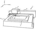
図1は、実施形態に係る印刷マスク材製造方法に用いられる加工機1を示す斜視図である。この加工機1は、市場に広く出回っている彫刻機を改良したものである。不動のステージ9の上面には、ワーク支持台2が形成されており、このワーク支持台2の上に、ワークとしてのプラスチック製のシート材100が固定されている。シート材の固定方法としては、クランプ固定、ネジ固定、吸引固定など、従来から周知のものを採用することができる。
Hereinafter, an embodiment of a printing mask material manufacturing method to which the present invention is applied will be described.
FIG. 1 is a perspective view showing a
ステージ9は、アーム3をx方向に移動可能に支持している。このアーム3は、ステージ9の長手方向であるy方向に延在しながら、ワーク支持台2の上空でワーク支持台2と所定の距離をおいて対向するように、ステージ9の長手方向一端部、及び他端部に支持されている。そして、ヘッド保持ステージ4をy方向に移動可能に支持している。また、ヘッド保持ステージ4は、エンドミル固定ヘッド5を回転させつつ、シート材100の厚み方向に沿ったZ方向に移動可能に保持している。更には、エアー吹き付けヘッド6を保持している。
The stage 9 supports the
エンドミル固定ヘッド5の先端には、後述するダイヤモンドエンドミル7が固定されている。また、エアー吹き付けヘッド6の先端には、吹き付けノズル8が固定されている。
A
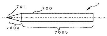
図2は、ダイヤモンドエンドミル7を示す側面図である。ダイヤモンドエンドミル7は、図示のように、全体としてペン状の形状をしている。その大部分は、支持金具としてのシャンク700が占めている。超硬からなるシャンク700は、円柱状の本体部700bと、その先端に形成された円錐状の先端部700aとを具備しており、本体部700bの後端部(図の右側の端部)が、エンドミル固定ヘッド7に把持固定される。ダイヤモンドエンドミル7の長さは、例えば40[mm]程度である。
FIG. 2 is a side view showing the
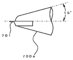
円錐状の先端部700aは、図3や図4に示されるように、根本側(図中右側)から先端側に向けて徐々に細くなる円錐状のテーパーを具備しており、その先端には、ダイヤモンド製の刃部701が固定されている。この刃部701は、図4に示されるように、シャンク700の回転中心軸線の位置に対して偏心した位置に固定される。
As shown in FIGS. 3 and 4, the conical tip 700a has a conical taper that gradually narrows from the root side (right side in the figure) toward the tip side. A
図5は、刃部701をその先端側から示す正面図である。ダイヤモンド製の刃部701は、シャンク700の先端部700aに固定される固定部701bと、ワークに摺擦してワークを切削加工するための刃先701aとを具備している。図中の点線の円は、刃先701aの回転軌道を示している。この円の直径方向において、刃先701aが全く存在しない領域であるクリアランスCは、例えば0.025[mm]程度である。また、直径方向において刃先701aが存在している領域の長さは例えば0.16[mm]程度である。
FIG. 5 is a front view showing the
図3に示されるように、シャンク700の先端部700aのテーパーは、先端側のテーパーと、これよりも傾斜(回転軸線に対する傾斜)の緩やかな後端側のテーパーとの2段になっている。後端側のテーパーの角度は、回転軸線に対して例えば15[°]程度である。
As shown in FIG. 3, the taper of the tip 700a of the
図1において、エンドミル固定ヘッド7の先端に固定されたエアー吹き付けヘッド8からは、流体としての圧縮エアーが吹き出される。吹き出された圧縮エアーは、エンドミル固定ヘッド7に固定されたダイヤモンドエンドミル7の刃部(701)やその周囲に吹き付けられる。
In FIG. 1, compressed air as a fluid is blown out from an
加工機1は、図示しないパーソナルコンピュータから送られてくるNCデータに基づいて、ダイヤモンドエンドミル7を回転させながら、x方向、y方向、z方向に移動させることで、シート材100をNCデータに従った順序で切削加工する。ダイヤモンドエンドミル7のx方向の動きについては、ステージ9上におけるアーム3のx方向の移動によって実現する。また、ダイヤモンドエンドミル7のy方向の動きについては、アーム3上におけるヘッド保持ステージ4のy方向の移動によって実現する。また、ダイヤモンドエンドミル7のz方向の動きについては、ヘッド保持ステージ4上におけるエンドミル固定ヘッド5のz方向の移動によって実現する。
Based on NC data sent from a personal computer (not shown), the
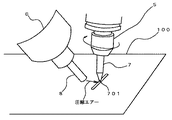
実施形態に係る印刷マスク材製造方法においては、次のようにして、プラスチック製(例えばPET製)のシート材に対して、真円状ではない複雑な形状の貫通開口を形成する。例えば、長穴状の貫通開口を形成する例について説明すると、まず、回転駆動するダイヤモンドエンドミル7により、回転長穴状の浅い凹部を形成する。具体的には、回転駆動するダイヤモンドエンドミル7の刃部701により、シート材100の表面を浅く切削しながら、ダイヤモンドエンドミル7をシート材100の表面方向に沿って移動させて、長穴状の凹部を浅く掘り込む。この際、図6に示されるように、吹き付けノズル8から吹き出した圧縮エアーを、切削加工中の刃部701やその周囲に吹き付ける。これにより、切削加工中の浅い凹部内から加工屑を吹き飛ばして、刃部701に加工屑を巻き付けてしまうことを防止する。切削によって発生した直後の加工屑を吹き飛ばすことにより、吹き飛ばされた加工屑の大きさは、0.06[mm]程度になる。これに対し、加工屑を吹き飛ばさないと、加工屑の大きさは0.2[mm]程度になり、それらの塊が刃部701に巻き付き易くなってしまう。
In the printing mask material manufacturing method according to the embodiment, a through-hole having a complicated shape that is not a perfect circle is formed on a plastic (for example, PET) sheet material as follows. For example, a description will be given of an example in which a long hole-shaped through opening is formed. First, a shallow concave portion having a rotating long hole shape is formed by a
長穴状の浅い凹部を形成したら、ダイヤモンドエンドミル7のz方向への移動により、刃部701をシート材100に対してより押し込んむ。そして、刃部701の周囲にエアーを吹き付けながらダイヤモンドエンドミル7を長穴に沿ってシート表面方向に移動させて凹部の深さをより大きくする。この際、図7に示されるように、凹部内で回転する刃部701の周囲にエアーを吹き付けることで、凹部内で発生する加工屑を凹部外に吹き飛ばして刃部701に対する加工屑の巻き付きを抑える。これにより、ダイヤモンドエンドミル7によって複雑な形状の貫通開口を良好に形成することが可能になる。図8に示されるように、バリの殆どない綺麗な長穴形状の貫通開口100aを形成することが可能である。
When the long hole-shaped shallow concave portion is formed, the
このように、実施形態に係る印刷マスク材製造方法では、機械加工だけで複雑な形状の貫通開口100aを形成することで、少量多品種のオンデマンド生産を実現することができる。しかも、設備投資としては、市場に出回っている安価な彫刻機など、エキシマレーザー装置に比べて遙かに安価なもので済むことから、エキシマレーザー装置を用いる場合に比べて、低コスト化を実現することができる。更には、耐久性に優れたダイヤモンド製の刃部701を具備するダイヤモンドエンドミル7を用いるので、すぐに摩耗してしまう合金製のエンドミルを用いる場合に比べて手コスト化を実現することができる。以上の結果、プラスチック製のシート材100に対して機械加工だけで複雑な形状の貫通開口100aを形成して、複雑な印刷パターンの印刷マスク材を安価にオンデマンド生産することができる。
As described above, in the printing mask material manufacturing method according to the embodiment, a small number of various types of on-demand production can be realized by forming the through-
なお、凹部をより深く掘り込んでいく際に、刃部701の周囲にエアーを吹き付けないと、図9に示されるように、凹部内に多量の加工屑を残してしまう。そして、凹部内に溜まった加工屑を刃部701に巻き付けて、巻き付いた加工屑によって切削加工を著しく阻害してしまうことから、図10に示されるように、商品にはならないほどの著しいバリを発生させてしまう。更に、加工屑が刃部701に無理な力をかけることから、刃部701の折れを頻繁に発生させてしまう。
In addition, when digging a recessed part deeper, if air is not sprayed around the
図3や図4に示されるように、シャンク700の先端部700aには、先端側から根本側に向けて太くなるテーパーを設けている。このテーパーにより、切削加工中の凹部内から出た加工屑をテーパーに沿って移動させることで、シート表面方向において加工屑を凹部の周囲に良好に散らす。これにより、凹部から排出された加工屑を凹部内に逆戻りさせてしまうことがなくなることから、刃部701への加工屑の巻き付きをより確実に抑えることができる。
As shown in FIGS. 3 and 4, the tip 700 a of the
また、実施形態に係る印刷マスク材製造方法では、上述したように、浅く形成した凹部をより深く掘り込んでいく際だけでなく、浅い凹部を掘り込む際にも、刃部701やその周囲にエアーを吹き付けている。かかる構成では、浅い凹部を得た時点における凹部内での加工屑の量を減らすことで、浅い凹部を掘り込む操作から凹部をより深く掘り込む操作に切り替える際の切り替え初期におけるバリの発生をより抑えることができる。
Moreover, in the printing mask material manufacturing method according to the embodiment, as described above, not only when the recessed portion formed shallowly is dug deeper, but also when the shallow recessed portion is dug, the
加工機1には、ダイヤモンドエンドミル7によってシート材100を切削する際の切削負荷を測定する図示しない切削負荷測定手段を設けている。かかる切削負荷測定手段としては、例えば周知の3成分フォースリンクを例示することができる。3成分フォースリンクを、エンドミル固定ヘッド5における、回転するエンドミル把持部よりもヘッド根本側に設け、この3成分フォースリンクによってエンドミル固定ヘッド5を支えるようにする。これにより、例えば、図11に示されるように、ダイヤモンドエンドミル7にかかるx方向、y方向、z方向の切削負荷をそれぞれ測定することが可能になる。
The
また、切削負荷測定手段として、エンドミル把持部の回転駆動力を発揮するための駆動モータの消費電流を測定する電流計を用いてもよい。切削負荷が大きくなるほど、消費電流が大きくなることから、消費電流を切削負荷の代替特性として検出することが可能だからである。 Moreover, you may use the ammeter which measures the consumption current of the drive motor for exhibiting the rotational drive force of an end mill holding part as a cutting load measurement means. This is because the current consumption increases as the cutting load increases, so that the current consumption can be detected as an alternative characteristic of the cutting load.
刃部701が摩耗によって劣化してくると、切削負荷が大きくなっていくとともに、切削能力の低下によってバリを発生させ易くなっていく。そこで、切削負荷がある程度大きくなった時点を刃部701の寿命到達タイミングとみなして、ダイヤモンドエンドミル7を新しいものに交換する。これにより、ダイヤモンドエンドミル7を適切なタイミングで交換することで、ダイヤモンドエンドミル7を不適切に長期使用することによるバリの発生(歩留まりの低下)を抑えることができる。
When the
また、実施形態に係る印刷マスク材製造方法においては、シート材100として、図12に示されるように、プラスチック(例えばPET)からなる基材シート101の表面に、基材シート101よりも高い硬度の材料(例えばカーボン)からなる表面層102を被覆したものを用いる。このようなシート材100では、高硬度に起因して表面層102がバリを発生させ難いことに加えて、表面層102が基材シート101の加工屑のシート本体からの切断を促す。これにより、バリの発生をより抑えることができる。
Moreover, in the printing mask material manufacturing method which concerns on embodiment, as the sheet |
また、実施形態に係る印刷マスク材製造方法においては、ダイヤモンドエンドミル7のシャンク700として、超硬からなるものを用いていることから、一般的な金属からなるものを用いる場合に比べて、シャンク700の長寿命化を図ることができる。
Further, in the printing mask material manufacturing method according to the embodiment, the
次に、実施形態に係る印刷マスク材製造方法に、より特徴的な構成を付加した実施例の印刷マスク材製造方法について説明する。なお、以下に特筆しない限り、実施例に係る印刷マスク材製造方法の構成は、実施形態と同様である。
図13は、実施例に係る印刷マスク材製造方法で用いられるエンドミル固定ヘッド5と、その周囲構成とを鉛直方向下側から眺めた状態を平面図である。図示のようにエンドミル固定ヘッド5の周囲には、複数(8つ)のエアー吹き付けヘッド6が配設されている。それらエアー吹き付けヘッド6の吹き付けノズル8は、エンドミル固定ヘッド5に固定されたダイヤモンドエンドミル7の周囲に位置している。
Next, the printing mask material manufacturing method of the Example which added the more characteristic structure to the printing mask material manufacturing method which concerns on embodiment is demonstrated. Unless otherwise specified below, the configuration of the printing mask material manufacturing method according to the example is the same as that of the embodiment.
FIG. 13 is a plan view of the end mill fixed
加工機1の制御部は、ダイヤモンドエンドミル7を横方向に移動させている際に、8つの吹き付けノズル8のうち、ダイヤモンドエンドミル7の進行方向に対し、概ね反対方向になる吹き付けノズル8から圧縮エアーを選択的に吹き出させる制御を実施する。この制御のために、加工機1は、8つの吹き付けノズル8からの圧縮エアーの吹き出しをそれぞれ個別に入切するための8つの電磁弁を備えている。
When the
かかる構成では、貫通開口の加工中に横方向に移動している刃部701に対し、その進行方向にかかわらず、概ね反対方向から圧縮エアーを吹き付けることで、刃部701の進行方向にかかわらず、加工屑を良好に凹部から排出させることができる。なお、ダイヤモンドエンドミル7の刃部(701)やその周囲に吹き付ける流体として、圧縮エアーに代えて、酸化防止剤、窒素ガス(N2)、純水などを用いてもよい。
In such a configuration, regardless of the traveling direction, the compressed air is blown from the opposite direction to the
以上に説明したものは一例であり、本発明は、次の態様毎に特有の効果を奏する。
[態様A]
態様Aは、シート材(例えばシート材100)に印刷パターン用の複数の貫通開口(例えば貫通開口100a)を形成して印刷マスク材を製造する印刷マスク材製造方法において、前記貫通開口を形成するための工具として、ダイヤモンド製の刃部を支持金具(例えばシャンク700)の先端に固定したダイヤモンドエンドミルを用い、回転駆動している前記ダイヤモンドエンドミルの前記刃部(例えば刃部701)の周囲に流体を吹き付けながら、前記ダイヤモンドエンドミルを前記シート材の表面方向に移動させて所望の形状の凹部を浅く掘り込んだ後、前記刃部を前記シート材に対してより押し込んでから、前記刃部の周囲に流体を吹き付けながら前記ダイヤモンドエンドミルを前記表面方向に移動させて前記凹部の深さをより大きくする操作を実施して前記貫通開口を形成することを特徴とするものである。
What has been described above is merely an example, and the present invention has a specific effect for each of the following modes.
[Aspect A]
Aspect A is a printing mask material manufacturing method for manufacturing a printing mask material by forming a plurality of through openings (for example, through
[態様B]
態様Bは、態様Aにおいて、前記支持金具として、先端部に先端側から根本側に向けて太くなるテーパーを設けたものを用いたことを特徴とするものである。
[Aspect B]
Aspect B is characterized in that, in Aspect A, the support fitting is provided with a taper that is thickened from the tip side toward the root side at the tip portion.
[態様C]
態様Cは、態様A又はBにおいて、前記シート材の表面を切削して複雑な形状の浅い凹部を掘り込む際にも、前記刃部の周囲に流体を吹き付けることを特徴とするものである。
[Aspect C]
Aspect C is characterized in that, in Aspect B or A, fluid is sprayed around the blade portion even when the surface of the sheet material is cut to dig a shallow concave portion having a complicated shape.
[態様D]
態様Dは、態様A〜Cの何れかにおいて、流体(例えばエアー)を吹き付けるためのノズル(例えば吹き付けノズル8)を前記ダイヤモンドエンドミルの周囲に複数配設し、それらノズルのうち、前記ダイヤモンドエンドミルのシート表面に沿った進行方向に対し、概ね反対方向になるノズルから前記刃部に向けて流体を選択的に吹き付けることを特徴とするものである。
[Aspect D]
Aspect D includes a plurality of nozzles (for example, spray nozzle 8) for spraying fluid (for example, air) in any one of aspects A to C around the diamond end mill. A fluid is selectively sprayed toward the blade portion from a nozzle that is substantially opposite to the traveling direction along the sheet surface.
[態様E]
態様Eは、態様A〜Dの何れかにおいて、ダイヤモンドエンドミルによって前記シート材を切削する際の切削負荷を測定した結果に基づいて、前記ダイヤモンドエンドミルの交換時期を決定することを特徴とするものである。
[Aspect E]
Aspect E is characterized in that in any one of Aspects A to D, the replacement time of the diamond end mill is determined based on the result of measuring the cutting load when the sheet material is cut by the diamond end mill. is there.
[態様F]
態様Fは、態様A〜Eの何れかにおいて、前記シート材として、プラスチックからなる基材シートの表面に、前記基材シートよりも高い硬度の材料からなる表面層を被覆したものを用いることを特徴とするものである。
[Aspect F]
Aspect F uses, in any one of aspects A to E, as the sheet material, a surface of a base material sheet made of plastic coated with a surface layer made of a material having a hardness higher than that of the base material sheet. It is a feature.
[態様G]
態様Gは、態様A乃至Fの何れかにおいて、前記支持金具として、超硬からなるものを用いることを特徴とするものである。
[Aspect G]
Aspect G is characterized in that, in any one of Aspects A to F, the support fitting is made of cemented carbide.
1:加工機
7:ダイヤモンドエンドミル
8:吹き付けノズル(ノズル)
700:シャンク
700a:先端部
701:刃部
100:シート材
100a:貫通開口
1: Processing machine 7: Diamond end mill 8: Spray nozzle (nozzle)
700: Shank 700a: Tip portion 701: Blade portion 100:
Claims (7)
前記貫通開口を形成するための工具として、ダイヤモンド製の刃部を支持金具の先端に固定したダイヤモンドエンドミルを用い、
回転駆動している前記ダイヤモンドエンドミルの前記刃部の周囲に流体を吹き付けながら、前記ダイヤモンドエンドミルを前記シート材の表面方向に移動させて所望の形状の凹部を浅く掘り込んだ後、前記刃部を前記シート材に対してより押し込んでから、前記刃部の周囲に流体を吹き付けながら前記ダイヤモンドエンドミルを前記表面方向に移動させて前記凹部の深さをより大きくする操作を実施して前記貫通開口を形成することを特徴とする印刷マスク材製造方法。 In a printing mask material manufacturing method for manufacturing a printing mask material by forming a plurality of through openings for a printing pattern in a sheet material,
As a tool for forming the through-opening, using a diamond end mill with a diamond blade fixed to the tip of a support fitting,
While spraying a fluid around the blade portion of the diamond end mill that is rotationally driven, the diamond end mill is moved toward the surface of the sheet material to dig a concave portion of a desired shape shallowly, and then the blade portion is After further pressing into the sheet material, the diamond end mill is moved in the surface direction while spraying a fluid around the blade portion, and the depth of the concave portion is increased to perform the through opening. A printing mask material manufacturing method characterized by forming.
前記支持金具として、先端部に先端側から根本側に向けて太くなるテーパーを設けたものを用いたことを特徴とする印刷マスク材製造方法。 In the printing mask material manufacturing method of Claim 1,
A method for producing a printing mask material, characterized in that a taper that becomes thicker from the tip side toward the root side is provided at the tip portion as the support fitting.
前記シート材の表面を切削して複雑な形状の浅い凹部を掘り込む際にも、前記刃部の周囲に流体を吹き付けることを特徴とする印刷マスク材製造方法。 In the printing mask material manufacturing method of Claim 1 or 2,
A method for producing a printing mask material, wherein a fluid is sprayed around the blade portion even when the surface of the sheet material is cut to dig a shallow concave portion having a complicated shape.
流体を吹き付けるためのノズルを前記ダイヤモンドエンドミルの周囲に複数配設し、それらノズルのうち、前記ダイヤモンドエンドミルのシート表面に沿った進行方向に対し、概ね反対方向になるノズルから前記刃部に向けて流体を選択的に吹き付けることを特徴とする印刷マスク材製造方法。 In the printing mask material manufacturing method in any one of Claims 1 thru | or 3,
A plurality of nozzles for spraying a fluid are arranged around the diamond end mill, and among these nozzles, the nozzle is directed in a direction generally opposite to the traveling direction along the surface of the diamond end mill from the nozzle toward the blade portion. A method for producing a printing mask material, wherein a fluid is selectively sprayed.
ダイヤモンドエンドミルによって前記シート材を切削する際の切削負荷を測定した結果に基づいて、前記ダイヤモンドエンドミルの交換時期を決定することを特徴とする印刷マスク材製造方法。 In the printing mask material manufacturing method in any one of Claims 1 thru | or 4,
A printing mask material manufacturing method, comprising: determining a replacement time of the diamond end mill based on a result of measuring a cutting load when the sheet material is cut by a diamond end mill.
前記シート材として、プラスチックからなる基材シートの表面に、前記基材シートよりも高い硬度の材料からなる表面層を被覆したものを用いることを特徴とする印刷マスク材製造方法。 In the printing mask material manufacturing method in any one of Claims 1 thru | or 5,
A method for producing a printing mask material, comprising using, as the sheet material, a surface of a base material sheet made of plastic and a surface layer made of a material having a hardness higher than that of the base material sheet.
前記支持金具として、超硬からなるものを用いることを特徴とする印刷マスク材製造方法。 In the printing mask material manufacturing method in any one of Claims 1 thru | or 6,
A method for manufacturing a printing mask material, wherein the support metal fitting is made of cemented carbide.
Priority Applications (1)
| Application Number | Priority Date | Filing Date | Title |
|---|---|---|---|
| JP2013081465A JP2014200902A (en) | 2013-04-09 | 2013-04-09 | Manufacturing method of print mask material |
Applications Claiming Priority (1)
| Application Number | Priority Date | Filing Date | Title |
|---|---|---|---|
| JP2013081465A JP2014200902A (en) | 2013-04-09 | 2013-04-09 | Manufacturing method of print mask material |
Publications (1)
| Publication Number | Publication Date |
|---|---|
| JP2014200902A true JP2014200902A (en) | 2014-10-27 |
Family
ID=52351815
Family Applications (1)
| Application Number | Title | Priority Date | Filing Date |
|---|---|---|---|
| JP2013081465A Pending JP2014200902A (en) | 2013-04-09 | 2013-04-09 | Manufacturing method of print mask material |
Country Status (1)
| Country | Link |
|---|---|
| JP (1) | JP2014200902A (en) |
Cited By (3)
| Publication number | Priority date | Publication date | Assignee | Title |
|---|---|---|---|---|
| CN104646737A (en) * | 2014-12-31 | 2015-05-27 | 东莞美维电路有限公司 | Method for processing golden finger lead burrs |
| US20200198045A1 (en) * | 2018-12-21 | 2020-06-25 | Tf Massif Technologies Ltd. | Method of keeping a scriber tip clear of material and an ablation scriber head |
| KR20230085052A (en) * | 2021-12-06 | 2023-06-13 | (주)미래컴퍼니 | Method and apparatus for processing workpiece |
Citations (6)
| Publication number | Priority date | Publication date | Assignee | Title |
|---|---|---|---|---|
| JPH09309196A (en) * | 1996-05-22 | 1997-12-02 | Dainatoron Kk | Mask for cream solder printing and method of manufacturing the same |
| JPH11156627A (en) * | 1997-09-25 | 1999-06-15 | Mitsubishi Heavy Ind Ltd | End mill processing method and end mill processing apparatus |
| JPH11320339A (en) * | 1998-05-18 | 1999-11-24 | Mitsubishi Materials Corp | Method and apparatus for detecting tool wear of machine tool |
| JPH11320233A (en) * | 1998-05-19 | 1999-11-24 | Tomutekku:Kk | Hollow machining method |
| JP2003127019A (en) * | 2001-10-23 | 2003-05-08 | Micro Diamond Kk | End mill with single crystal diamond at its tip |
| JP2005144973A (en) * | 2003-11-19 | 2005-06-09 | Process Lab Micron:Kk | Perforated printing mask |
-
2013
- 2013-04-09 JP JP2013081465A patent/JP2014200902A/en active Pending
Patent Citations (6)
| Publication number | Priority date | Publication date | Assignee | Title |
|---|---|---|---|---|
| JPH09309196A (en) * | 1996-05-22 | 1997-12-02 | Dainatoron Kk | Mask for cream solder printing and method of manufacturing the same |
| JPH11156627A (en) * | 1997-09-25 | 1999-06-15 | Mitsubishi Heavy Ind Ltd | End mill processing method and end mill processing apparatus |
| JPH11320339A (en) * | 1998-05-18 | 1999-11-24 | Mitsubishi Materials Corp | Method and apparatus for detecting tool wear of machine tool |
| JPH11320233A (en) * | 1998-05-19 | 1999-11-24 | Tomutekku:Kk | Hollow machining method |
| JP2003127019A (en) * | 2001-10-23 | 2003-05-08 | Micro Diamond Kk | End mill with single crystal diamond at its tip |
| JP2005144973A (en) * | 2003-11-19 | 2005-06-09 | Process Lab Micron:Kk | Perforated printing mask |
Cited By (4)
| Publication number | Priority date | Publication date | Assignee | Title |
|---|---|---|---|---|
| CN104646737A (en) * | 2014-12-31 | 2015-05-27 | 东莞美维电路有限公司 | Method for processing golden finger lead burrs |
| US20200198045A1 (en) * | 2018-12-21 | 2020-06-25 | Tf Massif Technologies Ltd. | Method of keeping a scriber tip clear of material and an ablation scriber head |
| KR20230085052A (en) * | 2021-12-06 | 2023-06-13 | (주)미래컴퍼니 | Method and apparatus for processing workpiece |
| KR102784571B1 (en) * | 2021-12-06 | 2025-03-26 | (주)미래컴퍼니 | Method and apparatus for processing workpiece |
Similar Documents
| Publication | Publication Date | Title |
|---|---|---|
| Yan et al. | Examination of wire electrical discharge machining of Al2O3p/6061Al composites | |
| JP3780840B2 (en) | Pre-spraying shape of the inner surface of a cylinder | |
| US20070006694A1 (en) | Cutting tool and cutting machine | |
| JP2006281416A (en) | Drilling device of printed circuit board | |
| JP2007196312A (en) | Saw wire and manufacturing method thereof | |
| Ahmed et al. | On the design and application of hybrid electrical discharge and arc machining process for enhancing drilling performance in Inconel 718 | |
| Chen | Fabrication of high-density micro holes by upward batch micro EDM | |
| JP2010076069A (en) | Machining method and apparatus therefor | |
| KR20210085132A (en) | Chip Removal Cutting Tool | |
| JP6389205B2 (en) | Machining method using drill and drill with coolant injection hole | |
| CN202155578U (en) | Multi-spray orifice gun drill | |
| JP2010253573A (en) | Drilling tool | |
| JP5360805B2 (en) | Tool positioning device | |
| JP4526325B2 (en) | Electrolyte jet processing method | |
| CN111571152A (en) | A kind of spinneret hole processing method of spinneret | |
| JP2014195863A (en) | End mill | |
| JP2014039963A (en) | Drill with coolant jet hole | |
| JP3146992U (en) | Drill spiral angle structure | |
| KR100628885B1 (en) | Carbide step drill for finishing holes in non-ferrous materials | |
| JP2010131646A (en) | Tip dresser | |
| JP2021171892A (en) | Inner surface processing method and inner surface processing device | |
| US12011766B2 (en) | Cutting part and lathe | |
| JP2014188628A (en) | Groove processing method | |
| JP2007260686A (en) | Resistance welding electrode | |
| CN108747250A (en) | A kind of carbide-tipped lathe tool processing method |
Legal Events
| Date | Code | Title | Description |
|---|---|---|---|
| A621 | Written request for application examination |
Free format text: JAPANESE INTERMEDIATE CODE: A621 Effective date: 20160316 |
|
| A977 | Report on retrieval |
Free format text: JAPANESE INTERMEDIATE CODE: A971007 Effective date: 20161222 |
|
| A131 | Notification of reasons for refusal |
Free format text: JAPANESE INTERMEDIATE CODE: A131 Effective date: 20170106 |
|
| A601 | Written request for extension of time |
Free format text: JAPANESE INTERMEDIATE CODE: A601 Effective date: 20170224 |
|
| A521 | Request for written amendment filed |
Free format text: JAPANESE INTERMEDIATE CODE: A523 Effective date: 20170427 |
|
| A02 | Decision of refusal |
Free format text: JAPANESE INTERMEDIATE CODE: A02 Effective date: 20170929 |