JP2014200904A - Internal grinder - Google Patents
Internal grinder Download PDFInfo
- Publication number
- JP2014200904A JP2014200904A JP2013081846A JP2013081846A JP2014200904A JP 2014200904 A JP2014200904 A JP 2014200904A JP 2013081846 A JP2013081846 A JP 2013081846A JP 2013081846 A JP2013081846 A JP 2013081846A JP 2014200904 A JP2014200904 A JP 2014200904A
- Authority
- JP
- Japan
- Prior art keywords
- grinding wheel
- workpiece
- grinding
- axis
- shaft
- Prior art date
- Legal status (The legal status is an assumption and is not a legal conclusion. Google has not performed a legal analysis and makes no representation as to the accuracy of the status listed.)
- Granted
Links
Images


Landscapes
- Grinding Of Cylindrical And Plane Surfaces (AREA)
Abstract
【課題】加工部の位置を測定する測定装置を用いることなく、被加工物の回転軸方向における加工部の位置精度を所望の値とできる内面研削盤を提供する。【解決手段】被加工物Wを回転させる主軸台5と、砥石車9を保持する砥石台7を備え、被加工物Wの内周面を研削する内面研削盤において、砥石台7の砥石車9が装着される側の端面に基準金14を装着し、被加工物Wの端面を基準金14に押し当てる。砥石車9を偏心して保持する砥石軸頭8を旋回させることにより、砥石車9を被加工物Wの半径方向へ移動させ被加工物Wに切込むように制御して、被加工物Wの内周面を研削する。【選択図】図2Provided is an internal grinding machine capable of setting a position accuracy of a processed part in a rotation axis direction of a workpiece to a desired value without using a measuring device for measuring the position of the processed part. In an internal grinding machine that includes a headstock 5 for rotating a workpiece W and a grinding wheel platform 7 that holds a grinding wheel 9, and grinds the inner peripheral surface of the workpiece W, the grinding wheel of the grinding wheel platform 7 is provided. The reference metal 14 is mounted on the end surface on the side where 9 is mounted, and the end surface of the workpiece W is pressed against the reference metal 14. By rotating the grinding wheel head 8 that eccentrically holds the grinding wheel 9, the grinding wheel 9 is controlled to move in the radial direction of the work W and cut into the work W. Grind the inner surface. [Selection] Figure 2
Description
本発明は、内面研削盤に関するものである。 The present invention relates to an internal grinding machine.
内面研削盤において、被加工物の回転軸方向における加工部の位置精度を高めることを目的として、加工部の位置を測定装置で測定して被加工物と砥石車の相対位置を制御することが行われている。(例えば、特許文献1参照)。 In an internal grinding machine, in order to increase the position accuracy of the processed part in the direction of the rotation axis of the work piece, the position of the processed part is measured by a measuring device to control the relative position of the work piece and the grinding wheel. Has been done. (For example, refer to Patent Document 1).
内面研削盤においては、被加工物を保持する主軸と砥石車を保持する砥石軸台はベッド上に支持されており、ベッド、主軸、砥石軸台の熱変位による位置誤差を生じる。この誤差を補正するために測定装置が用いられるが、加工部の位置を測定装置で測定して被加工物と砥石車の相対位置を制御するためには、測定をするための工程が必要であり、この工程の時間だけ加工時間が長くなる。 In an internal grinding machine, a main shaft for holding a workpiece and a grindstone head for holding a grinding wheel are supported on a bed, and a positional error is caused by thermal displacement of the bed, the main shaft, and the grindstone head. A measuring device is used to correct this error. However, in order to control the relative position between the workpiece and the grinding wheel by measuring the position of the processing part with the measuring device, a process for measuring is required. Yes, the processing time becomes longer by the time of this process.
本発明は上記事情に鑑みてなされたものであり、内面研削盤において、加工部の位置を測定する測定装置を用いることなく、被加工物の回転軸方向における加工部の位置精度を所望の値とできる内面研削盤を提供することを目的とする。 The present invention has been made in view of the above circumstances, and in the internal grinding machine, the position accuracy of the processed portion in the direction of the rotation axis of the workpiece is set to a desired value without using a measuring device that measures the position of the processed portion. It is an object of the present invention to provide an internal grinding machine that can be used.
上記の課題を解決するため、請求項1に係る発明の特徴は、主軸を回転自在に支持する主軸台と、前記主軸の回転軸線と平行な回転軸線を有し、砥石車を保持する砥石軸を備え、
前記砥石車の回転軸線を含む研削作用部の断面形状を、前記主軸により回転駆動される被加工物の内周面に転写して所望の形状に研削する内面研削盤において、
前記主軸に対して、軸方向には移動可能で回転方向には拘束され、前記被加工物を把持する把持装置と、
前記砥石軸を自らの旋回軸線に対して偏心して保持する砥石軸頭本体と、
前記砥石軸頭本体を旋回自在に支持する砥石台本体と、
前記砥石軸頭本体を旋回させることにより、前記砥石軸を前記被加工物の半径方向へ移動させる砥石車切込み手段と、
前記砥石台本体の前記砥石車が保持される側の端面に装着され、前記把持装置と対向する基準金と、
前記把持装置を前記基準金の方向へ押し当てる押付手段と、
前記押付手段により前記被加工物を前記基準金に押し当て、前記砥石車切込み手段により前記砥石車を前記被加工物に切込むように、前記主軸と前記砥石軸と前記押付手段と前記砥石車切込み手段を制御して内面研削を行う制御装置を備え、
前記所望の形状の所定部位と前記被加工物の前記基準金と接触する端面の間の前記砥石軸線方向の距離は、前記所定部位を研削する前記砥石車の部位と前記基準金の前記被加工物との接触面の間の前記砥石軸線方向の距離と等しいことである。
In order to solve the above-mentioned problem, a feature of the invention according to
In an internal grinding machine that transfers the cross-sectional shape of the grinding action portion including the rotation axis of the grinding wheel to the inner peripheral surface of the workpiece that is rotationally driven by the main shaft and grinds it to a desired shape,
A gripping device that is movable in the axial direction and restrained in the rotational direction with respect to the main shaft, and grips the workpiece;
A grindstone head body that holds the grindstone shaft eccentrically with respect to its own turning axis; and
A grinding wheel head main body that rotatably supports the grinding wheel head body;
Grinding wheel cutting means for moving the grinding wheel shaft in the radial direction of the workpiece by turning the grinding wheel head body;
A reference metal mounted on an end surface of the grinding wheel base body on the side where the grinding wheel is held, and facing the gripping device,
Pressing means for pressing the gripping device in the direction of the reference metal;
The main shaft, the grinding wheel shaft, the pressing means, and the grinding wheel so that the workpiece is pressed against the reference metal by the pressing means, and the grinding wheel is cut into the workpiece by the grinding wheel cutting means. Provided with a control device that performs internal grinding by controlling the cutting means,
The distance in the grinding wheel axis direction between the predetermined portion of the desired shape and the end surface of the workpiece that contacts the reference gold is determined by the grinding wheel portion grinding the predetermined portion and the workpiece of the reference gold. It is equal to the distance of the grindstone axis direction between the contact surfaces with a thing.
請求項2に係る発明の特徴は、請求項1に関わる発明において、前記砥石軸の軸方向の位置の基準と前記砥石軸頭本体の軸方向の位置の基準が、前記基準金の近傍に配置されることである。
The invention according to
請求項3に係る発明の特徴は、請求項1または請求項2に関わる発明において、前記基準金は、前記主軸の回転軸線と同軸の軸心回りに回転可能に支持されることである。
A feature of the invention according to
請求項1に係る発明によれば、被加工物に転写された所望の形状の所定部位と被加工物の基準金との接触する端面の前記砥石軸線方向の間の距離は、所定部位を研削する砥石車の部位と基準金の被加工物と接触する面の間の砥石軸線方向の距離のみで決定される。砥石車と基準金は、ベッドを介することなく同一の砥石台に装着されているため、砥石車と基準金の温度差が少ない。このため、砥石車と基準金の間の砥石軸線方向の距離の熱による変動が小さくなる。結果として、被加工物の軸方向寸法誤差が小さい内面研削盤を実現できる。
According to the invention of
請求項2に係る発明によれば、砥石車と偏心軸の軸方向の基準位置が基準金の近傍に配置されるので、砥石車と基準金の軸方向の距離が短いので、熱変位による誤差がさらに小さい内面研削盤を実現できる。 According to the second aspect of the present invention, since the axial reference position between the grinding wheel and the eccentric shaft is arranged in the vicinity of the reference gold, the distance between the grinding wheel and the reference gold in the axial direction is short. Can achieve an internal grinder with even smaller.
請求項3に係る発明によれば、研削加工時に基準金が被加工物と共に回転するので、基準金の磨耗が小さい内面研削盤を実現できる。
According to the invention which concerns on
以下、本発明の実施の形態を説明する。
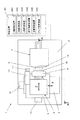
図1に示すように、内面研削盤1は、ベッド2を備え、ベッド2上にベース3を備え、ベース3上にはベース3によりX軸方向に往復可能に支持され、モータ12で往復駆動されるテーブル4を備えている。さらに、テーブル4上にはX軸に直交するZ軸方向にモータ13により往復駆動される主軸台5を備えている。主軸台5は、被加工物Wを把持する把持装置6を回転自在に支持し、Z軸と平行な軸線周りに回転駆動する。主軸台5の側面には、ドレスロール11を回転駆動するドレス10が配置されている。
また、ベッド2上には、砥石車9を回転自在に支持する砥石台7が、砥石車9の回転軸線がZ軸と平行になるように固定されている。
Embodiments of the present invention will be described below.
As shown in FIG. 1, the
On the
この内面研削盤1は、所定のプログラムを実行することで研削加工や砥石成形を実行する制御装置30を備えている。制御装置30の機能的構成として、テーブル4の送りを制御するX軸制御装置301、主軸台5の送りを制御するZ軸制御装置302、砥石軸の旋回切込みを制御するU軸制御装置303、砥石車9の回転を制御する砥石車制御装置304、主軸51の回転を制御する主軸制御装置305、ドレス10を制御するドレス制御装置306などを具備している。
The
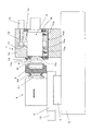
図2に基づき、砥石台7の詳細について説明する。
ベッド2上に固定された砥石台本体70に備えた静圧軸受70a、70bにより、砥石車9を回転自在に支持する砥石軸頭8(詳細は後に説明する)を、Z軸と平行な軸線周りに旋回自在に支持している。また、砥石台本体70の砥石車9の装着される側の端部には、砥石軸頭8の軸方向の基準位置となる静圧スラスト軸受70cを備えており、反対の端面にはプレート74を備えている。砥石台本体70、砥石軸頭8、プレート74により液圧室78を構成している。
静圧軸受70a、70b、静圧スラスト軸受70c、液圧室78には、流路70dを経由して、図示しない圧油供給装置から圧油が供給される。これにより、砥石軸頭8は、回転自在に支持されると共に、液圧室78の圧力により静圧スラスト軸受70cに押付けられる。
砥石軸頭8の外周の軸方向の中央部には歯車71が固定されており、歯車71は、外周に歯車を備えたピニオン72と噛合っており、ピニオン72は砥石台本体70により回転自在に支持され、モータ73で回転駆動される。
砥石台7は、以上の構成を備えており、砥石台本体70の砥石車9の装着される側の端面には、主軸の回転軸線と垂直な平面14aを備えた基準金14が装着されている。
Based on FIG. 2, the detail of the
A grinding wheel head 8 (details will be described later) that supports the grinding
The
A
The
図2に基づき、主軸台5と把持装置6の詳細について説明する。
主軸台5は主軸51を回転自在に支持している。被加工物Wを把持する把持装置6は、主軸51に対して回転は拘束され軸方向には所定の距離だけ移動可能に支持されている。把持装置6は、皿ばね52により主軸51の先端側に所定の力で押付けられている。
砥石車9と把持装置6は、被加工物Wの内径に砥石車9が挿入可能な相対位置に配置されている。また、基準金14は、被加工物Wの端面が基準金14の平面14aに接触可能な位置に配置されている。
The details of the
The
The
図3に基づき砥石軸頭8の詳細について説明する。
砥石軸頭本体80は、砥石軸81を砥石軸頭本体80の内周面に備えた静圧軸受80a、80bにより回転自在に支持する。砥石軸81は一端にフランジ部81aを備えこの端面には砥石車9を装着可能なねじを備えている、また、他端部にはスラストリング82が装着され他端の終端部にはモータ83のロータが連結されている。また、砥石軸頭本体80の砥石車9の装着される側の端部には、砥石軸81の軸方向の基準位置となる静圧スラスト軸受80cを備えている。砥石軸頭本体80、砥石軸81、スラストリング82により液圧室84を構成している。
静圧軸受80a、80b、静圧スラスト軸受80c、液圧室84には、流路80dと溝70eと流路70dを経由して、図示しない圧油供給装置から圧油が供給される。これにより、砥石軸81は、回転自在に支持されると共に、液圧室84の圧力によりモータ取り付け方向に作用する力を受け、フランジ部81aは静圧スラスト軸受80cに押付けられている。
The details of the
The grindstone shaft head
The
ここで、砥石軸頭本体80の外周面と静圧軸受80a、80bの内周面は、偏心しており偏心量はeである。このため、図3のB−B断面矢視図である図4に示すように、砥石軸頭本体80の回転軸線Pと砥石軸81の回転軸線Qも偏心しており偏心量はeである。砥石軸頭本体80には歯車71が固定されおり、その歯面がピニオン72の歯面と噛合っている。このため、ピニオン72が回転すると砥石軸頭本体80が回転し、砥石軸81の回転軸線Qは回転軸線Pの周りを半径eの円周を描き旋回する。この旋回運動をU軸と称する。主軸51の回転軸線と砥石車9の回転軸線Qが同軸になるのは、水平線に対して点Pと点Qを結ぶ線が角度Θ0をなすときであり、この位置をU軸加工原点と称する。
Here, the outer peripheral surface of the
内面研削盤1による研削方法を、図5のフローチャートに基づき説明する。
はじめに、工作物搬入出位置において被加工物Wを把持装置6に装着する。工作物搬入出位置は図6の(a)図に示す位置である(S1)。テーブル4をX軸方向へ送り、図6の(b)図に示すように、被加工物Wと砥石車9の回転軸線が同軸となるX軸加工開始位置へ主軸台5を位置決めする(S2)。主軸台5をZ軸方向へ送り、被加工物Wと基準金14が接触した後、さらに、所定の距離だけ皿ばね52を圧縮するZ軸加工開始位置へ主軸台5を位置決めする。Z軸加工開始位置は図6の(c)図に示す位置である。この時、図7に示すように、把持装置6は皿ばね52により所定の力で被加工物Wを基準金14に押し付け、その力は皿ばね52の復元力となる。この状態で、主軸台5と砥石軸台7の間で熱変位等による相対位置変動があっても、その変動は皿ばね52の伸縮で吸収される。このため、被加工物の端面からの加工部の最大径の位置の軸方向の距離mは、基準面14aと砥石車9の最大径の位置の距離nに等しくなる。(S3)。
A grinding method by the internal grinding
First, the workpiece W is mounted on the gripping device 6 at the workpiece loading / unloading position. The workpiece loading / unloading position is the position shown in FIG. 6 (a) (S1). The table 4 is fed in the X-axis direction, and the
主軸51を回転させて、被加工物Wを回転させる(S4)。砥石車9をU軸方向へ送り、被加工物Wに切込む。図4において、モータ73によりピニオン72を左回転させて、歯車71を介して砥石軸頭本体80を所定の角度Θ1まで右回りに回転させる。これにより、図8の(b)図に示すように、砥石車9はU軸方向へ旋回し、被加工物Wの内周面に切込まれ、被加工物Wの内径溝を所定の径に研削する(S5)。砥石車9をU軸加工原点へ戻す。モータ73によりピニオン72を右回転させて、歯車71を介して砥石軸頭本体80を所定の角度Θ0まで左回りに回転させる。これにより、図8の(a)図に示すように、砥石車9は被加工物Wと同軸上のU軸加工原点に位置決めされる(S6)。主軸台5をZ軸方向で砥石軸台から離れる方法へ送り、図5の(b)図の位置に位置決めする(S7)。テーブル4をX軸方向へ送り、図6の(a)図に示す工作物搬入出位置に位置決めし、工作物を取り出す(S8)。
The
以上のように、本実施事例の内面研削盤1を用いて研削を行うと、被加工物Wの端面から溝の最大径の位置までの寸法は、基準金14の平面14aから砥石車9の最大径の位置までの距離mで決まる。すなわち、ベッド2や主軸台5などの部位の熱変位などによる誤差の影響を受けないで研削ができる。
また、基準金14と、砥石軸頭本体80の軸方向の位置の基準である静圧スラスト軸受70cと、砥石軸81の軸方向の位置の基準である静圧スラスト軸受70cの砥石軸方向の距離が近いため、基準金14と砥石軸81の間の熱変位は小さくなる。
以上より、本実施事例の内面研削盤1を用いると、測定装置を用いることなく、被加工物Wの軸方向の加工位置を所望の精度に研削することができる。
As described above, when grinding is performed using the inner
In addition, the
As described above, when the internal grinding
上記実施例では、基準金14を砥石台本体70に固定したが、主軸台5の回転軸線と同軸で回転できるように支持してもよい。この場合、被加工物と基準金の間の相対すべりがなくなり、摩擦による発熱や、基準金の消耗を防止できる。
In the above embodiment, the
W:被加工物 2:ベッド 3:ベース 4:テーブル 5:主軸台 6:把持装置 7:砥石台 8:砥石軸頭 9:砥石車 14:基準金 70c:静圧スラスト軸受 71:歯車 72:ピニオン 30:制御装置 301:X軸制御装置 302:Z軸制御装置 303:U軸制御装置 304:砥石軸制御装置 305:主軸制御装置
W: Workpiece 2: Bed 3: Base 4: Table 5: Main spindle 6: Gripping device 7: Grinding wheel base 8: Grinding wheel head 9: Grinding wheel 14:
Claims (3)
前記砥石車の回転軸線を含む研削作用部の断面形状を、前記主軸により回転駆動される被加工物の内周面に転写して所望の形状に研削する内面研削盤において、
前記主軸に対して、軸方向には移動可能で回転方向には拘束され、前記被加工物を把持する把持装置と、
前記砥石軸を自らの旋回軸線に対して偏心して保持する砥石軸頭本体と、
前記砥石軸頭本体を旋回自在に支持する砥石台本体と、
前記砥石軸頭本体を旋回させることにより、前記砥石軸を前記被加工物の半径方向へ移動させる砥石車切込み手段と、
前記砥石台本体の前記砥石車が保持される側の端面に装着され、前記把持装置と対向する基準金と、
前記把持装置を前記基準金の方向へ押し当てる押付手段と、
前記押付手段により前記被加工物を前記基準金に押し当て、前記砥石車切込み手段により前記砥石車を前記被加工物に切込むように、前記主軸と前記砥石軸と前記押付手段と前記砥石車切込み手段を制御して内面研削を行う制御装置を備え、
前記所望の形状の所定部位と前記被加工物の前記基準金と接触する端面の間の前記砥石軸線方向の距離は、前記所定部位を研削する前記砥石車の部位と前記基準金の前記被加工物との接触面の間の前記砥石軸線方向の距離と等しい内面研削盤。 A spindle stock that rotatably supports the spindle, a rotation axis parallel to the rotation axis of the spindle, and a grinding wheel shaft that holds the grinding wheel,
In an internal grinding machine that transfers the cross-sectional shape of the grinding action portion including the rotation axis of the grinding wheel to the inner peripheral surface of the workpiece that is rotationally driven by the main shaft and grinds it to a desired shape,
A gripping device that is movable in the axial direction and restrained in the rotational direction with respect to the main shaft, and grips the workpiece;
A grindstone head body that holds the grindstone shaft eccentrically with respect to its own turning axis; and
A grinding wheel head main body that rotatably supports the grinding wheel head body;
Grinding wheel cutting means for moving the grinding wheel shaft in the radial direction of the workpiece by turning the grinding wheel head body;
A reference metal mounted on an end surface of the grinding wheel base body on the side where the grinding wheel is held, and facing the gripping device,
Pressing means for pressing the gripping device in the direction of the reference metal;
The main shaft, the grinding wheel shaft, the pressing means, and the grinding wheel so that the workpiece is pressed against the reference metal by the pressing means, and the grinding wheel is cut into the workpiece by the grinding wheel cutting means. Provided with a control device that performs internal grinding by controlling the cutting means,
The distance in the grinding wheel axis direction between the predetermined portion of the desired shape and the end surface of the workpiece that contacts the reference gold is determined by the grinding wheel portion grinding the predetermined portion and the workpiece of the reference gold. An internal grinder equal to the distance in the grinding wheel axis direction between the contact surfaces with the object.
Priority Applications (1)
| Application Number | Priority Date | Filing Date | Title |
|---|---|---|---|
| JP2013081846A JP6107348B2 (en) | 2013-04-10 | 2013-04-10 | Internal grinding machine |
Applications Claiming Priority (1)
| Application Number | Priority Date | Filing Date | Title |
|---|---|---|---|
| JP2013081846A JP6107348B2 (en) | 2013-04-10 | 2013-04-10 | Internal grinding machine |
Publications (2)
| Publication Number | Publication Date |
|---|---|
| JP2014200904A true JP2014200904A (en) | 2014-10-27 |
| JP6107348B2 JP6107348B2 (en) | 2017-04-05 |
Family
ID=52351817
Family Applications (1)
| Application Number | Title | Priority Date | Filing Date |
|---|---|---|---|
| JP2013081846A Expired - Fee Related JP6107348B2 (en) | 2013-04-10 | 2013-04-10 | Internal grinding machine |
Country Status (1)
| Country | Link |
|---|---|
| JP (1) | JP6107348B2 (en) |
Cited By (1)
| Publication number | Priority date | Publication date | Assignee | Title |
|---|---|---|---|---|
| CN111906600A (en) * | 2020-08-29 | 2020-11-10 | 中国航发南方工业有限公司 | Eccentric cavity inner end surface grinding method and device |
Citations (6)
| Publication number | Priority date | Publication date | Assignee | Title |
|---|---|---|---|---|
| JPH02109673A (en) * | 1988-10-18 | 1990-04-23 | Koyo Mach Ind Co Ltd | Multi-stage grinding device |
| JPH0623666A (en) * | 1992-07-09 | 1994-02-01 | Mitsui Seiki Kogyo Co Ltd | Automatic positioning method of internal grinding wheel with dressing |
| JPH0760639A (en) * | 1993-08-23 | 1995-03-07 | Toyo A Tec Kk | Work device for work having groove |
| WO1999001254A1 (en) * | 1997-07-04 | 1999-01-14 | Lidköping Machine Tools AB | Internal abrasive machine |
| JP2003136400A (en) * | 2001-11-05 | 2003-05-14 | Honda Motor Co Ltd | Machining method of half crankshaft |
| JP2008221433A (en) * | 2007-03-15 | 2008-09-25 | Jtekt Corp | Grinding equipment |
-
2013
- 2013-04-10 JP JP2013081846A patent/JP6107348B2/en not_active Expired - Fee Related
Patent Citations (6)
| Publication number | Priority date | Publication date | Assignee | Title |
|---|---|---|---|---|
| JPH02109673A (en) * | 1988-10-18 | 1990-04-23 | Koyo Mach Ind Co Ltd | Multi-stage grinding device |
| JPH0623666A (en) * | 1992-07-09 | 1994-02-01 | Mitsui Seiki Kogyo Co Ltd | Automatic positioning method of internal grinding wheel with dressing |
| JPH0760639A (en) * | 1993-08-23 | 1995-03-07 | Toyo A Tec Kk | Work device for work having groove |
| WO1999001254A1 (en) * | 1997-07-04 | 1999-01-14 | Lidköping Machine Tools AB | Internal abrasive machine |
| JP2003136400A (en) * | 2001-11-05 | 2003-05-14 | Honda Motor Co Ltd | Machining method of half crankshaft |
| JP2008221433A (en) * | 2007-03-15 | 2008-09-25 | Jtekt Corp | Grinding equipment |
Cited By (2)
| Publication number | Priority date | Publication date | Assignee | Title |
|---|---|---|---|---|
| CN111906600A (en) * | 2020-08-29 | 2020-11-10 | 中国航发南方工业有限公司 | Eccentric cavity inner end surface grinding method and device |
| CN111906600B (en) * | 2020-08-29 | 2021-09-28 | 中国航发南方工业有限公司 | Eccentric cavity inner end surface grinding method and device |
Also Published As
| Publication number | Publication date |
|---|---|
| JP6107348B2 (en) | 2017-04-05 |
Similar Documents
| Publication | Publication Date | Title |
|---|---|---|
| RU2676540C1 (en) | Steady rest for additional support of central workpiece regions during machining, in particular bearing points on crankshafts, and grinding machine having such steady rest | |
| JP2012529378A (en) | Grinding support device | |
| JP6252270B2 (en) | Truing method for grinding wheel of grinding machine and grinding machine | |
| WO2014002624A1 (en) | Grinding processing device and method for controlling same | |
| US10537971B2 (en) | Measuring steady rest for supporting and measuring central workpiece regions grinding machine with such a measuring steady rest, and method for supporting and measuring central workpiece regions | |
| JP6303568B2 (en) | Tapered roller grinding apparatus and tapered roller grinding method | |
| JP5125391B2 (en) | Swivel device and cylindrical grinder provided with the same | |
| JP6005529B2 (en) | Centerless grinding method and centerless grinding apparatus for edge portion of tapered surface | |
| JP6006546B2 (en) | Shaft-shaped workpiece processing equipment | |
| JP6107348B2 (en) | Internal grinding machine | |
| JP2005254333A (en) | Cylindrical grinding machine and grinding method | |
| CN111843622B (en) | Grinding method and grinding machine | |
| JP5402546B2 (en) | Cylindrical workpiece grinding method | |
| JP5206194B2 (en) | Truing method and truing device for grinding wheel | |
| JP2008307633A (en) | Workpiece grinding method | |
| JP2005246499A (en) | Truing method and device | |
| JP5425570B2 (en) | Processing method and apparatus for trunnion of tripod type constant velocity joint | |
| JP5970964B2 (en) | Grinding resistance measuring method and grinding machine | |
| JP7021455B2 (en) | Processing equipment | |
| JP2005169530A (en) | Grinding machine and grinding method | |
| JP2013154462A (en) | Truing device of grinding machine | |
| JP5916121B2 (en) | Shaft-shaped workpiece processing equipment | |
| JP5085941B2 (en) | Cylindrical grinding machine and external grinding method using cylindrical grinding machine | |
| JP5262437B2 (en) | Truing method and grinding method for grinding wheel | |
| JP6135287B2 (en) | Grinder |
Legal Events
| Date | Code | Title | Description |
|---|---|---|---|
| A621 | Written request for application examination |
Free format text: JAPANESE INTERMEDIATE CODE: A621 Effective date: 20160315 |
|
| A977 | Report on retrieval |
Free format text: JAPANESE INTERMEDIATE CODE: A971007 Effective date: 20161222 |
|
| TRDD | Decision of grant or rejection written | ||
| A01 | Written decision to grant a patent or to grant a registration (utility model) |
Free format text: JAPANESE INTERMEDIATE CODE: A01 Effective date: 20170207 |
|
| A61 | First payment of annual fees (during grant procedure) |
Free format text: JAPANESE INTERMEDIATE CODE: A61 Effective date: 20170220 |
|
| R150 | Certificate of patent or registration of utility model |
Ref document number: 6107348 Country of ref document: JP Free format text: JAPANESE INTERMEDIATE CODE: R150 |
|
| LAPS | Cancellation because of no payment of annual fees |