JP2014201344A - Beverage packing bottle - Google Patents

Beverage packing bottle Download PDF

Info

Publication number
JP2014201344A
JP2014201344A JP2013079849A JP2013079849A JP2014201344A JP 2014201344 A JP2014201344 A JP 2014201344A JP 2013079849 A JP2013079849 A JP 2013079849A JP 2013079849 A JP2013079849 A JP 2013079849A JP 2014201344 A JP2014201344 A JP 2014201344A
Authority
JP
Japan
Prior art keywords
bottle
wheel
block
rib
water supply
Prior art date
Legal status (The legal status is an assumption and is not a legal conclusion. Google has not performed a legal analysis and makes no representation as to the accuracy of the status listed.)
Pending
Application number
JP2013079849A
Other languages
Japanese (ja)
Inventor
弘晃 種本
Hiroaki Tanemoto
弘晃 種本
Current Assignee (The listed assignees may be inaccurate. Google has not performed a legal analysis and makes no representation or warranty as to the accuracy of the list.)
NIHON PURE WATER Inc
Original Assignee
NIHON PURE WATER Inc
Priority date (The priority date is an assumption and is not a legal conclusion. Google has not performed a legal analysis and makes no representation as to the accuracy of the date listed.)
Filing date
Publication date
Application filed by NIHON PURE WATER Inc filed Critical NIHON PURE WATER Inc
Priority to JP2013079849A priority Critical patent/JP2014201344A/en
Publication of JP2014201344A publication Critical patent/JP2014201344A/en
Pending legal-status Critical Current

Links

Images

Landscapes

  • Containers Having Bodies Formed In One Piece (AREA)
  • Filling Of Jars Or Cans And Processes For Cleaning And Sealing Jars (AREA)

Abstract

PROBLEM TO BE SOLVED: To provide a beverage packing bottle formed so as to be deformed by compression and be used stably in a beverage packing system having complicated processes.SOLUTION: A beverage packing bottle 1 comprises: a volume part 1a for storing beverage; and a cylindrical inlet/outlet part 1b that is connected to the volume part 1a at one end, has a smaller cross-sectional area than that of the volume part 1a, and has an opening 1c at the other end. The beverage packing bottle 1 can be transported with the volume part 1a deformed by compression in the axial direction of the inlet-outlet part 1b. There are ribs formed at 3 or more parts of the side of the inlet/outlet part 1b in the axial direction of the bottle 1, which are vertical to the axis and can be the positional reference in the axial direction.

Description

本発明は、飲料を充填するためのボトルであって、特に、圧縮変形させ容積を減縮した状態で飲料充填システムに投入し、飲料充填システム内で容積を拡張した上で飲料を充填するものに関する。   BACKGROUND OF THE INVENTION 1. Field of the Invention The present invention relates to a bottle for filling a beverage, and more particularly to a bottle filled with a beverage after being compressed and deformed and charged into the beverage filling system in a reduced volume and expanded in the beverage filling system. .

飲料充填システムは、新たに製造した飲料充填ボトル(以下、単にボトルともいう。)あるいは一旦流通後に回収したボトルを洗浄して飲用水などの飲料を充填し、キャップを装着して密封するシステムである。このようなシステムにおいて使用されるボトルの中には、輸送コストを低減するために、ボトルを一旦圧縮変形させて体積を減縮させた状態で運搬し、圧縮変形した状態で飲料充填システムに投入し、システム内で拡張するようにしたものがある。   The beverage filling system is a system for cleaning newly filled beverage filling bottles (hereinafter also simply referred to as “bottles”) or bottles collected after distribution, filling them with beverages such as drinking water, and attaching caps to seal them. is there. Among the bottles used in such a system, in order to reduce the transportation cost, the bottle is once compressed and deformed and transported in a reduced volume, and the compressed and deformed state is put into the beverage filling system. , There is something that was extended in the system.

このような飲料充填ボトルは、飲料を保持する容積部と、注ぎ口が開口する筒状の給排水部からなり、容積部は上下(給排水部の軸方向)に圧縮変形可能とするために肉厚が薄く形成されているのが一般的である。そうすると、飲料充填システム内で容積部を保持してボトルを移動させたり位置決めをしたりすることは困難となる。従って、このような飲料充填システム内では、ボトルを保持し位置決めの基準とするために、給排水部の肉厚は厚く形成するとともに給排水部の軸に垂直なリブを設ける場合がある。   Such a beverage filling bottle is composed of a volume portion for holding a beverage and a cylindrical water supply / drainage portion with an opening of a spout, and the volume portion is thick in order to be compressible and deformable vertically (in the axial direction of the water supply / drainage portion). Is generally formed thinly. If it does so, it will become difficult to hold | maintain a volume part within a drink filling system, and to move and position a bottle. Therefore, in such a beverage filling system, in order to hold the bottle and use it as a reference for positioning, the thickness of the water supply / drainage portion may be formed thick and a rib perpendicular to the axis of the water supply / drainage portion may be provided.

すなわち、飲料充填システム内では、上記のリブをガイドすることで位置決めの基準とするとともに、リブを保持部材で保持することでボトルを移動させるのである。しかしながら、飲料充填システムにおける工程が複雑になり、一の工程から他の工程に移行する際に装置から装置へとボトルを引き渡す必要がある場合には、給排水部に単一のリブが存在しても、これを複数の保持部材で保持し続けることや、位置決めの基準とし続けることが困難になる場合があった。   That is, in the beverage filling system, the rib is guided to be a reference for positioning, and the bottle is moved by holding the rib with the holding member. However, when the process in the beverage filling system becomes complicated and it is necessary to hand over the bottle from device to device when moving from one process to another, there is a single rib in the water supply / drainage section. However, there are cases where it is difficult to continue to hold this with a plurality of holding members and to keep it as a positioning reference.

また、このようなボトルでは、上述のように容積部の肉厚が薄く形成されているので、流通過程や飲料充填システム内においてボトル同士または、ボトルを収納する容器とボトルとが衝突し或いは摩擦することでボトルが損傷し、飲料の漏れなどの原因になる場合があった。   Moreover, in such a bottle, since the thickness of the volume part is formed thinly as described above, the bottles collide with each other or in the distribution process or in the beverage filling system, or the bottle and the bottle collide or friction. Doing so could damage the bottle and cause beverage leakage.

特開2006−137455号公報JP 2006-137455 A 特開2006−001575号公報JP 2006-001575 A 特開2006−008133号公報JP 2006008133 A 特開2006−051718号公報JP 2006-051718 A

本発明は、上記の現状に鑑みて案出されたものであり、その目的は、圧縮変形可能に形成されるとともに、複雑な工程からなる飲料充填システムにおいても安定的に使用可能な飲料充填ボトルを提供することである。また、飲料充填システム内や流通過程において耐久性に優れ安定して使用可能な飲料充填ボトルを提供することである。   The present invention has been devised in view of the above-described present situation, and an object of the present invention is to provide a beverage filling bottle that is formed so as to be compressible and can be stably used even in a beverage filling system comprising complicated processes. Is to provide. Another object of the present invention is to provide a beverage filling bottle that has excellent durability and can be used stably in the beverage filling system and in the distribution process.

上記課題を解決するための本発明は、飲料を保持する容積部と、該容積部に一端が接続され該容積部より小さい断面積を有するとともに他端に開口部が設けられた筒状の給排水部とからなり該給排水部の軸方向に前記容積部を圧縮変形させて運搬可能な飲料充填ボトルであって、
前記給排水部の側面には、前記軸に垂直に設けられ、該ボトルの該軸方向の位置基準となり得るリブが該軸方向の3箇所以上に設けられたことを特徴とする。
The present invention for solving the above problems is a cylindrical water supply / drainage having a volume part for holding a beverage, one end connected to the volume part and having a smaller cross-sectional area than the volume part, and an opening at the other end. A beverage filling bottle that can be transported by compressing and deforming the volume part in the axial direction of the water supply / drainage part,
On the side surface of the water supply / drainage unit, ribs that are provided perpendicular to the shaft and can serve as a reference for the position of the bottle in the axial direction are provided at three or more locations in the axial direction.

上述のように、給排水部の軸方向に圧縮変形可能な飲料充填ボトルを、飲料充填システム内で移動させ或いは位置決めするには、安定性の観点から、圧縮変形させない給排水部を比較的肉厚に形成しておき、筒状の給排水部の側面にリブを設けて軸方向の位置基準にするとともに、移動させる際には、保持部材を前記リブに当接させて飲料充填ボトルを保持部材にぶら下げるような形で保持することが行われている。   As described above, in order to move or position the beverage filling bottle that can be compressed and deformed in the axial direction of the water supply / drainage unit in the beverage filling system, from the viewpoint of stability, the water supply / drainage unit that is not compressed and deformed is relatively thick. A rib is provided on the side surface of the cylindrical water supply / drainage unit to provide an axial position reference, and when moving, the holding member is brought into contact with the rib to hang the beverage filling bottle from the holding member. It is carried out in such a form.

しかしながら、飲料充填システムの工程が複雑化・大型化した場合には、システムの途中で装置から装置へボトルを引き渡す場合が数多く生じる。その際には、リブが一箇所しかない場合には、リブに当接した状態でボトルを保持している保持部材から、次の工程を実施する装置の保持部材に引き渡す際の引き渡し方法及び保持部材構造が複雑になる虞がある。また、飲料充填システムにおいては、ボトルの内部を洗浄する必要があるが、その際にはボトルを上下反転させて保持する必要がある。この場合、リブが一つしかない場合には、保持部材がリブを上下から挟み込む構成にする必要があるなど、装置が複雑化してしまう虞がある。   However, when the process of the beverage filling system becomes complicated and large, there are many cases where bottles are handed over from device to device in the middle of the system. In that case, when there is only one rib, the delivery method and holding when delivering from the holding member holding the bottle in contact with the rib to the holding member of the apparatus performing the next step The member structure may be complicated. In the beverage filling system, it is necessary to clean the inside of the bottle, and in that case, it is necessary to hold the bottle upside down. In this case, when there is only one rib, there is a possibility that the apparatus becomes complicated, for example, the holding member needs to be configured to sandwich the rib from above and below.

それに対し、本発明ではリブを給排水部の軸方向の3箇所以上に設けることにしたので、飲料充填システム内でボトルを装置から装置へ引き渡す場合にも、引き渡す側と引き渡される側の装置の保持部材が異なるリブに当接して飲料充填ボトルを保持することが可能になる。これにより、引き渡す側と引き渡される側の装置の保持部材が重複してボトルを保持することを可能にし、飲料充填システムにおけるボトルの移動をより安定化することができる。また、保持部材でリブとリブの間の空間を保持することにより、飲料充填ボトルの上下を反転させた場合にも、保持部材の上下のいずれかのリブにボトルの自重で保持部材を当接させることができ、安定してボトルを保持することが可能となる。   In contrast, in the present invention, since ribs are provided at three or more locations in the axial direction of the water supply / drainage unit, even when the bottle is delivered from the device to the device in the beverage filling system, the delivery side and the delivery side device are held. It becomes possible to hold | maintain a drink filling bottle in contact with a rib from which a member differs. Thereby, the holding member of the apparatus of the handing over side and the handing over side can hold | maintain a bottle redundantly, and the movement of the bottle in a drink filling system can be stabilized more. In addition, by holding the space between the ribs with the holding member, even when the beverage filling bottle is turned upside down, the holding member is brought into contact with either the upper or lower rib of the holding member by its own weight. It is possible to hold the bottle stably.

また、本発明においては、各々の前記リブは前記給排水部の側面の全周に亘り設けられているようにしてもよい。そうすれば、飲料充填システム内におけるボトルの姿勢(給排水部の軸回りの角度位置)によらず、保持部材を確実にリブに当接させることができる。その結果、リブを利用してボトルを安定して保持することが可能である。   In the present invention, each rib may be provided over the entire circumference of the side surface of the water supply / drainage unit. If it does so, a holding member can be made to contact | abut to a rib reliably irrespective of the attitude | position (angular position around the axis | shaft of a water supply / drainage part) in the drink filling system. As a result, the bottle can be stably held using the rib.

また、本発明においては、前記容積部は前記軸に平行方向から見て、一部に直線部分を含む外形を有するようにしてもよい。   In the present invention, the volume portion may have an outer shape partially including a straight portion when viewed from a direction parallel to the axis.

ここで、上述のように、圧縮変形可能に形成されたボトルの容積部は肉厚が薄く形成される場合が多い。そうすると、流通過程や飲料充填システム内でボトル同士または、ボトルを収納する容器とボトルとが衝突し或いは摩擦することで、ボトルが損傷する場合があった。また、この場合、衝突或いは摩擦する場所が曲面で小さな面積に負荷が集中すると損傷が生じ易くなる。   Here, as described above, the volume portion of the bottle formed so as to be compressible and deformable is often formed to be thin. In this case, the bottles may be damaged by collision or friction between the bottles or the container storing the bottles and the bottles in the distribution process or the beverage filling system. Further, in this case, the place where the collision or friction occurs is a curved surface, and if the load is concentrated on a small area, damage is likely to occur.

それに対し、本発明においては、給排水部の軸に平行方向から見て、容積部の外形に直線部分が含まれているようにしたので、ボトル同士またはボトルを収納する容器(例えば、段ボール箱)とボトルとを面接触させることが可能になる。これにより、ボトル同士またはボトルを収納する容器とボトルとが線接触または点接触することを抑制し、容積部における面積が小さい部分に負荷が集中することを抑制できる。結果として、容積部の損傷
を抑制することが可能となる。
On the other hand, in the present invention, since the linear portion is included in the outer shape of the volume portion when viewed from the direction parallel to the axis of the water supply / drainage unit, the containers for storing the bottles or the bottles (for example, cardboard boxes) And the bottle can be brought into surface contact. Thereby, it can suppress that the container which accommodates bottles or a bottle and a bottle carry out a line contact or a point contact, and can suppress that a load concentrates on a part with a small area in a volume part. As a result, damage to the volume portion can be suppressed.

また、その際、前記容積部は前記軸に平行方向から見て、多角形の外形を有するようにしてもよい。そうすれば、より確実に、容積部の外形の平面部分に負荷が生じるようにすることができる。結果として、小さい面積の部分に負荷が集中することを抑制できる。   In this case, the volume portion may have a polygonal shape as viewed from a direction parallel to the axis. If it does so, a load can be made to generate | occur | produce more reliably in the plane part of the external shape of a volume part. As a result, it is possible to suppress the load from being concentrated on a small area.

また、前記容積部は前記軸に平行方向から見て、六角形の外形を有するようにしてもよい。これにより、容積部を所謂ハニカム形状とすることができ、容積部の圧縮方向以外の方向に対する強度を向上させることが可能となる。また、飲料充填ボトルを集合させた場合にボトルを蜂の巣状に並べることが可能となり、集合体全体の強度を向上させることが可能となる。   The volume portion may have a hexagonal outer shape when viewed from a direction parallel to the axis. Thereby, the volume part can be formed into a so-called honeycomb shape, and the strength of the volume part in a direction other than the compression direction can be improved. Further, when the beverage filling bottles are assembled, the bottles can be arranged in a honeycomb shape, and the strength of the entire assembly can be improved.

なお、上記の手段は、可能な限り互いに組み合わせて使用することができる。   In addition, said means can be used in combination with each other as much as possible.

本発明によれば、圧縮変形させ容積を減縮した状態でボトルを飲料充填システムに投入し、飲料充填システム内でボトルの容積を拡張した上で飲料を充填する飲料充填システムであって、複雑な工程を有するものにおいても、飲料充填ボトルを安定的に使用することができる。また、飲料充填システム内や流通過程におけるボトルの耐久性を向上させることができる。   According to the present invention, there is provided a beverage filling system in which a bottle is charged into a beverage filling system in a state of being compressed and deformed and the volume is reduced, and the beverage is filled after expanding the volume of the bottle in the beverage filling system. Also in what has a process, a drink filling bottle can be used stably. Moreover, the durability of the bottle in the beverage filling system or in the distribution process can be improved.

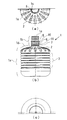
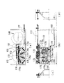
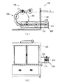
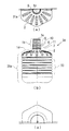
本発明の実施例1におけるボトルの概略構成を示す図である。It is a figure which shows schematic structure of the bottle in Example 1 of this invention. 本発明の前提となる飲料充填システム全体の概略構成を示す図である。It is a figure which shows schematic structure of the whole drink filling system used as the premise of this invention. 本発明の前提となる搬入ブロック及び拡張ブロックの概略構成を示す図である。It is a figure which shows schematic structure of the carrying-in block and expansion block used as the premise of this invention. 本発明の前提となる拡張ブロックのうち、リブ押圧コンベヤ付近の図である。It is a figure of a rib press conveyor vicinity among the expansion blocks used as the premise of this invention. 本発明の前提となる洗浄ブロックにおけるノズルの概略構成を示す図である。It is a figure which shows schematic structure of the nozzle in the washing | cleaning block used as the premise of this invention. 本発明の前提となる洗浄ブロックにおける実際の洗浄工程を示す図である。It is a figure which shows the actual washing | cleaning process in the washing | cleaning block used as the premise of this invention. 本発明の前提となる充填ブロックの概略構成を示す図である。It is a figure which shows schematic structure of the filling block used as the premise of this invention. 本発明の前提となる打栓ブロックの概略構成を示す図である。It is a figure which shows schematic structure of the stoppering block used as the premise of this invention. 本発明の前提となる搬出ブロックの概略構成を示す図である。It is a figure which shows schematic structure of the carrying-out block used as the premise of this invention. 本発明の本実施例2におけるボトルの概略構成を示す図である。It is a figure which shows schematic structure of the bottle in the present Example 2 of this invention. 容積部が円形の外形を有するボトルと、容積部の外形の一部に直線部を有するボトルとが容器に収納された場合について説明するための図である。It is a figure for demonstrating the case where the bottle in which a volume part has a circular external shape, and the bottle which has a linear part in a part of external shape of a volume part are accommodated in the container. 本発明の本実施例3におけるボトルの概略構成を示す図である。It is a figure which shows schematic structure of the bottle in this Example 3 of this invention. 本発明の本実施例3におけるボトルを並べた場合の概略構成を示す図である。It is a figure which shows schematic structure at the time of arranging the bottle in this Example 3 of this invention.

以下、本発明の実施の形態について、図面を参照して詳細に説明する。
〔実施例1〕
図1には、本実施例に係る飲用水充填システム100によって飲用水を充填するボトル1を示す。図1(a)は平面図、図1(b)は側面図、図1(c)は底面図を示す。なお、本明細書のボトル1に関し、図1(a)における紙面手前側が上側、紙面奥側を下側と表現する。また、図1(a)及び図1(c)は、少なくとも中心線に対して対象な図となるので、主に中心線の片側についてのみ描かれている。
Hereinafter, embodiments of the present invention will be described in detail with reference to the drawings.
[Example 1]
FIG. 1 shows a bottle 1 that is filled with drinking water by a drinking water filling system 100 according to the present embodiment. 1A is a plan view, FIG. 1B is a side view, and FIG. 1C is a bottom view. In addition, regarding the bottle 1 of the present specification, the front side of the paper surface in FIG. 1A is expressed as the upper side, and the back side of the paper surface is expressed as the lower side. In addition, FIGS. 1A and 1C are drawings that are targeted at least with respect to the center line, and are therefore mainly drawn only on one side of the center line.

図1(a)及び図1(c)に示すように、ボトル1は、上下方向から見て円形の断面を有する。また。図1(b)に示すように、ボトル1は、中空円柱状で飲用水を受容する容積部1aと、容積部1aの上面に設けられ容積部1aより小径の円筒形状を有し、容積部1aに連結されることで外部との間で飲用水を授受するための給排水部1bとからなる。給排水部1bの上端には飲用水授受のための開口部1cが設けられている。   As shown in FIGS. 1 (a) and 1 (c), the bottle 1 has a circular cross section when viewed in the vertical direction. Also. As shown in FIG. 1 (b), the bottle 1 has a hollow cylindrical shape with a volume part 1a for receiving drinking water, and a cylindrical shape with a smaller diameter than the volume part 1a provided on the upper surface of the volume part 1a. It consists of the water supply / drainage part 1b for giving / receiving drinking water between the exterior by connecting with 1a. An opening 1c for giving and receiving drinking water is provided at the upper end of the water supply / drainage unit 1b.

容積部1aの上面における給排水部1bの周囲の領域である肩部1dには、ボトル1全体としての強度を確保するために放射状に形成された縦リブ2が16箇所設けられている。また、容積部1aの側面にはボトル1自体を上下方向に変形させるための蛇腹形状の蛇腹部3が設けられている。この蛇腹部3が設けられているので、ボトル1を成形後に上下方向から押圧しまたは引張ることで、蛇腹部3を選択的に変形させることができ、ボトル1を上下方向に容易に圧縮または復元させることが可能となっている。   The shoulder 1d, which is a region around the water supply / drainage portion 1b on the upper surface of the volume portion 1a, is provided with 16 vertical ribs 2 that are radially formed to ensure the strength of the bottle 1 as a whole. A bellows-shaped bellows portion 3 for deforming the bottle 1 itself in the vertical direction is provided on the side surface of the volume portion 1a. Since the bellows portion 3 is provided, the bellows portion 3 can be selectively deformed by pressing or pulling the bottle 1 from the vertical direction after molding, and the bottle 1 can be easily compressed or restored in the vertical direction. It is possible to make it.

なお、給排水部1bの側面には、基準リブとしての上側リブ5、中間リブ6、下側リブ7の3つのリブが設けられている。図1(a)には、上側リブ5のみが現れているが、上側リブ5は上から見ると円形の外形に90度毎に4箇所のDカットを施した形状となっている。また、上側リブ5、中間リブ6及び下側リブ7は同じ形状を有している。さらに、上側リブ5、中間リブ6及び下側リブ7は、図1(b)に示すように、上下方向には等間隔で設けられている。以下、上側リブ5と中間リブ6と、その間の給排水部1bの側面とで形成される部分を上側リブ空間10と呼ぶ。また、中間リブ6と下側リブ7と、その間の給排水部1bの側面とで形成される領域を下側リブ空間11と呼ぶ。   In addition, three ribs, that is, an upper rib 5, an intermediate rib 6, and a lower rib 7 as reference ribs are provided on the side surface of the water supply / drainage portion 1b. In FIG. 1A, only the upper rib 5 appears, but the upper rib 5 has a circular outer shape with four D-cuts every 90 degrees when viewed from above. The upper rib 5, the intermediate rib 6 and the lower rib 7 have the same shape. Further, the upper rib 5, the intermediate rib 6 and the lower rib 7 are provided at equal intervals in the vertical direction as shown in FIG. Hereinafter, a portion formed by the upper rib 5 and the intermediate rib 6 and the side surface of the water supply / drainage portion 1b therebetween is referred to as an upper rib space 10. A region formed by the intermediate rib 6 and the lower rib 7 and the side surface of the water supply / drainage portion 1b therebetween is called a lower rib space 11.

次に、図2を用いて、本実施例の飲用水充填システム100の概略構成及び作用について説明する。図2(a)はシステム全体の平面図、図2(b)は正面図、図2(c)は左側面図を示す。飲用水充填システム100においては、ボトル成型工場で成形された後に、上下方向に圧縮された状態のボトル1を搬入口101から投入すると、搬入用コンベヤ102によってハウジング105内に自動的に導入される。ここで、搬入口101及び搬入用コンベヤ102を含めて搬入ブロック103と呼ぶ。また、その過程においてボトル1は本来のサイズまで拡張される。その後、ハウジング105内において、ボトル1の内部が洗浄され、飲用水が充填され、キャップが打栓される。そして、それらの工程が終了した後に、ボトル1は搬出用コンベヤ212によって搬出口211まで運搬される。ここでは、搬出用コンベヤ212と搬出口211を含めて搬出ブロック220と呼ぶ。   Next, the schematic configuration and operation of the drinking water filling system 100 of the present embodiment will be described with reference to FIG. 2A is a plan view of the entire system, FIG. 2B is a front view, and FIG. 2C is a left side view. In the potable water filling system 100, when the bottle 1 in a state of being vertically compressed after being formed at a bottle molding factory is introduced from the carry-in entrance 101, it is automatically introduced into the housing 105 by the carry-in conveyor 102. . Here, the carry-in entrance 101 and the carry-in conveyor 102 are collectively referred to as a carry-in block 103. In the process, the bottle 1 is expanded to the original size. Thereafter, the inside of the bottle 1 is washed in the housing 105, filled with drinking water, and the cap is stoppered. And after those processes are complete | finished, the bottle 1 is conveyed by the carrying-out conveyor 212 to the carrying-out port 211. FIG. Here, the carry-out conveyor 212 and the carry-out port 211 are collectively referred to as a carry-out block 220.

飲用水充填システム100には、搬入ブロック103及び搬出ブロック220の他に、機能別に考えると四つのブロックが形成されている。第一のブロックは、ボトル1内に空気を所定の圧力で流入させることで圧縮されたボトル1を使用状態にまで拡張する拡張ブロック110である。第二のブロックは、拡張ブロック110において拡張されたボトル1の内部を洗浄する洗浄ブロック140である。第三のブロックは、洗浄ブロック140において内部を洗浄され、且つ水切りがされたボトル1に飲用水を充填する充填ブロック170である。第四のブロックは、充填ブロック170において飲用水が充填された後のボトル1にキャップを打栓して密封する打栓ブロック200である。   In addition to the carry-in block 103 and the carry-out block 220, the potable water filling system 100 is formed with four blocks when considered by function. The first block is an expansion block 110 that expands the compressed bottle 1 to a use state by allowing air to flow into the bottle 1 at a predetermined pressure. The second block is a cleaning block 140 that cleans the inside of the bottle 1 expanded in the expansion block 110. The third block is a filling block 170 that fills drinking water into the bottle 1 whose interior has been cleaned and drained in the cleaning block 140. The fourth block is a stoppering block 200 that seals the bottle 1 with a cap after the potable water is filled in the filling block 170.

本実施例においては、拡張ブロック110は、搬入用コンベヤ102の延長上でボトル1が直線移動している間に空気がボトル1に流入され拡張するように構成されている。また、洗浄ブロック140は、ボトル1が洗浄ホイール141の外周部に保持されて洗浄ホイール141の円周上を周回移動している間にボトル1の内部が洗浄されるように構成されている。また、充填ブロック170は、ボトル1が充填ホイール172の外周部に保持されて充填ホイール172の円周上を周回移動している間にボトル1に飲用水が充填されるように構成されている。さらに、打栓ブロック200は、ボトル1が打栓ホイール201の外周部に保持されて打栓ホイール201の円周上を周回移動している間にボトル1に
キャップが装着されるように構成されている。
In this embodiment, the expansion block 110 is configured such that air flows into the bottle 1 and expands while the bottle 1 moves linearly on the extension of the carry-in conveyor 102. The cleaning block 140 is configured such that the inside of the bottle 1 is cleaned while the bottle 1 is held on the outer peripheral portion of the cleaning wheel 141 and moves around the circumference of the cleaning wheel 141. Further, the filling block 170 is configured such that the bottle 1 is filled with drinking water while the bottle 1 is held on the outer peripheral portion of the filling wheel 172 and moves around the circumference of the filling wheel 172. . Further, the stopper block 200 is configured such that the cap is attached to the bottle 1 while the bottle 1 is held on the outer peripheral portion of the stopper wheel 201 and moves around the circumference of the stopper wheel 201. ing.

また、本実施例においては、拡張ブロック110から洗浄ブロック140にボトル1が移行する際には、第一方向転換ブロック125においてボトル1の進行方向が変更される。具体的には、第一方向転換ホイール127の外周に保持され、第一方向転換ホイール127の円周上をボトル1が所定の角度だけ周回移動することにより方向転換される。同様に、洗浄ブロック140から充填ブロック170にボトル1が移行する際には、第二方向転換ブロック155においてボトル1の進行方向が変更される。具体的には、第二方向転換ホイール157の外周部にボトル1が保持され、第二方向転換ホイール157の円周上を所定の角度だけ周回移動することによりボトル1が方向転換される。   In this embodiment, when the bottle 1 moves from the expansion block 110 to the cleaning block 140, the traveling direction of the bottle 1 is changed in the first direction changing block 125. Specifically, it is held on the outer periphery of the first direction changing wheel 127, and the direction is changed when the bottle 1 moves around the circumference of the first direction changing wheel 127 by a predetermined angle. Similarly, when the bottle 1 moves from the cleaning block 140 to the filling block 170, the traveling direction of the bottle 1 is changed in the second direction changing block 155. Specifically, the bottle 1 is held on the outer peripheral portion of the second direction changing wheel 157, and the bottle 1 is changed in direction by moving around the circumference of the second direction changing wheel 157 by a predetermined angle.

すなわち、搬入口101から搬入され搬入用コンベヤ102に載置されたボトル1は、直線上を進行しながら拡張ブロック110において拡張される。次に、ボトル1は第一方向転換ブロック125に移行しハウジング105内における進行方向が変更される。第一方向転換ブロック125で進行方向が変更されたボトル1は、洗浄ブロック140に移行する。洗浄ブロック140においてボトル1が周回移動し、その間にボトル1の内部が洗浄される。   That is, the bottle 1 carried in from the carry-in port 101 and placed on the carry-in conveyor 102 is expanded in the expansion block 110 while proceeding on a straight line. Next, the bottle 1 moves to the first direction changing block 125 and the traveling direction in the housing 105 is changed. The bottle 1 whose traveling direction has been changed in the first direction changing block 125 moves to the cleaning block 140. In the washing block 140, the bottle 1 moves around, and the inside of the bottle 1 is washed during that time.

洗浄ブロック140において洗浄されたボトル1は第二方向転換ブロック155に移行し、進行方向が変更された上で、充填ブロック170に渡される。充填ブロック170においてはボトル1が周回移動し、その間に飲用水が充填される。充填ブロック170において飲用水が充填されたボトル1は打栓ブロック200に渡される。打栓ブロック200において周回移動し、その間に給排水部1bの開口部1cに打栓されたボトル1は、搬出用コンベヤ211に渡され、搬出用コンベヤ211上を直線移動し、搬出口212から搬出される。   The bottle 1 cleaned in the cleaning block 140 is transferred to the second direction changing block 155, and the traveling direction is changed, and then transferred to the filling block 170. In the filling block 170, the bottle 1 moves around, and drinking water is filled in the meantime. The bottle 1 filled with drinking water in the filling block 170 is delivered to the stoppering block 200. The bottle 1 circulated around the plugging block 200 and plugged into the opening 1c of the water supply / drainage unit 1b in the meantime is transferred to the carry-out conveyor 211, moved linearly on the carry-out conveyor 211, and carried out from the carry-out port 212. Is done.

次に、図3及び図4を用いて本実施例の搬入ブロック103及び拡張ブロック110について詳細に説明する。図3(a)は、搬入ブロック103、拡張ブロック110と、第一方向転換ブロック125の一部を示す平面図である。図3(b)は、拡張ブロック110のうち、搬入用コンベヤ102付近の正面図である。ここで搬入用コンベヤ102は、前述のように搬入ブロック103を構成するとともに、拡張ブロック110の一部を構成することになる。   Next, the carry-in block 103 and the expansion block 110 of this embodiment will be described in detail with reference to FIGS. 3 and 4. FIG. 3A is a plan view showing a part of the carry-in block 103, the expansion block 110, and the first direction change block 125. FIG. 3B is a front view of the vicinity of the carry-in conveyor 102 in the expansion block 110. Here, the carry-in conveyor 102 constitutes the carry-in block 103 and a part of the expansion block 110 as described above.

また、図4(a)は、拡張ブロック110のうち、後述するリブ押圧コンベヤ116付近の平面図である。図4(b)は、拡張ブロック110のうち、後述するリブ押圧コンベヤ116付近の正面図である。図4(c)は同右側面図である。上述のように、ボトル1は、上下に圧縮され変形した状態で搬入口101に搬入され、作業者によって搬入用コンベヤ102まで運ばれる。この搬入口101は、搬入用コンベヤ102にボトル1を導入するための待機スペースである。搬入用コンベヤ102まで運ばれたボトル1は、搬入用コンベヤ102の作動によってハウジング105の方向に移動する。   FIG. 4A is a plan view of the vicinity of the rib pressing conveyor 116 described later in the expansion block 110. FIG. 4B is a front view of the vicinity of the rib pressing conveyor 116 described later in the expansion block 110. FIG. 4C is a right side view of the same. As described above, the bottle 1 is carried into the carry-in port 101 in a state of being compressed and deformed up and down, and is carried to the carry-in conveyor 102 by the operator. The carry-in port 101 is a standby space for introducing the bottle 1 into the carry-in conveyor 102. The bottle 1 carried to the carry-in conveyor 102 moves toward the housing 105 by the operation of the carry-in conveyor 102.

搬入用コンベヤ102によって、ボトル1が移動した先には、ボトル1の給排水部1bの進行方向に対して左右方向の位置を規制する左右ガイド112が設けられている。この左右ガイド112には、始端に左右横方向にテ―パ状に広がった導入部112aが設けられており、ボトル1が移動して給排水部1bが導入部112aに侵入し、左右ガイド112の幅が徐々に狭まることで、ボトル1の左右方向(図3(a)における上下方向)の位置が搬入用コンベヤ102の中央部に揃うようになっている。また、導入部112aの下流側における左右ガイド112の左右両側には、ボトル1の進行方向下流側に延びた長板状の部材でありローラ113aを複数備えた圧縮ガイド113が設けられている。   A left and right guide 112 that regulates the position in the left and right direction with respect to the traveling direction of the water supply / drainage portion 1 b of the bottle 1 is provided at the tip of the bottle 1 moved by the carry-in conveyor 102. The left and right guide 112 is provided with an introduction portion 112a that spreads in the form of a taper in the left and right lateral direction at the starting end, and the bottle 1 moves and the water supply / drainage portion 1b enters the introduction portion 112a. By gradually narrowing the width, the positions of the bottles 1 in the left-right direction (vertical direction in FIG. 3A) are aligned with the central portion of the carry-in conveyor 102. Further, on both the left and right sides of the left and right guides 112 on the downstream side of the introduction part 112a, there are provided compression guides 113 each having a plurality of rollers 113a which are long plate-like members extending downstream in the traveling direction of the bottle 1.

この圧縮ガイド113は、下流側の端部113bで回動可能に支持されており、バネ力により反時計回りに付勢されている。そして、ローラ113aによってボトル1の肩部1dを下方向に押圧可能に配置されている。また、圧縮ガイド113の下流側の端部113bには、端部113bと同軸に回転可能で径がより大きい下流側ローラ113dが設けられている。また、圧縮ガイド113における複数のローラ113aの上流側には回転可能で、下流側ローラ113dと略同じ径を有する上流側ローラ113cが設けられている。そして、上流側ローラ113cと、下流側ローラ113dと、その間に配置された複数個のローラ113aには、丸ベルト113eが掛けられている。さらに、下流側ローラ113dには、図示しないモータが接続されており、丸ベルト113eの移動速度が搬入コンベヤ102と同じ速度になるように、下流側ローラ113dを回転させる。   The compression guide 113 is rotatably supported by the downstream end 113b, and is biased counterclockwise by a spring force. And it arrange | positions so that the shoulder part 1d of the bottle 1 can be pressed below with the roller 113a. Further, the downstream end 113b of the compression guide 113 is provided with a downstream roller 113d that can rotate coaxially with the end 113b and has a larger diameter. Further, an upstream roller 113c that is rotatable and has the same diameter as the downstream roller 113d is provided on the upstream side of the plurality of rollers 113a in the compression guide 113. A round belt 113e is hung on the upstream roller 113c, the downstream roller 113d, and the plurality of rollers 113a disposed therebetween. Further, a motor (not shown) is connected to the downstream roller 113d, and the downstream roller 113d is rotated so that the moving speed of the round belt 113e is the same as that of the carry-in conveyor 102.

ボトル1は、この圧縮ガイド113の下を通過する際に、下方向にさらに圧縮変形する。より具体的には、圧縮ガイド113のローラ113aが回転しながら、そして丸ベルト113eが移動しながらボトル1の左右両側の肩部1dを下側に押圧することで、進行方向の抵抗を増加させることなく、ボトル1は上下方向にさらに圧縮される。圧縮ガイド113は、前述のように下流側の端部113bの回転軸の周りに回動可能に設けられている。よって、搬入用コンベヤ102によってボトル1が図3(a)の下流側に移動すると、ボトル1の肩部1dは、回転軸113bの高さで規定される一定高さまで押さえつけられ、ボトル1は予め定められたサイズまで圧縮される。   When the bottle 1 passes under the compression guide 113, it is further compressed and deformed downward. More specifically, while the roller 113a of the compression guide 113 is rotating and the round belt 113e is moving, the shoulder 1d on both the left and right sides of the bottle 1 is pressed downward to increase the resistance in the traveling direction. Instead, the bottle 1 is further compressed in the vertical direction. As described above, the compression guide 113 is provided so as to be rotatable around the rotation axis of the downstream end 113b. Therefore, when the bottle 1 is moved to the downstream side of FIG. 3A by the carry-in conveyor 102, the shoulder 1d of the bottle 1 is pressed down to a certain height defined by the height of the rotating shaft 113b, and the bottle 1 is Compressed to a specified size.

拡張ブロック110における左右ガイド112及び圧縮ガイド113の下流側には、ボトル1の進行方向に水平に延びた長板状の部材であって、ボトル1の給排水部1bを左右から挟むように設けられたリブガイド115が設けられている。このリブガイド115は、左右ガイド112から連続してボトル1の給排水部1bの左右方向の位置を規制するとともに、その上下方向の位置も規制するものである。このリブガイド115は、ボトル1がその始端115aに到達した際に、左右両側の長板状の部材が上側リブ5と中間リブ6の間、すなわち上側リブ空間10に侵入するように構成されている。   On the downstream side of the left and right guide 112 and the compression guide 113 in the expansion block 110, a long plate-like member extending horizontally in the direction of travel of the bottle 1 is provided so as to sandwich the water supply / drainage portion 1b of the bottle 1 from the left and right. A rib guide 115 is provided. The rib guide 115 regulates the horizontal position of the water supply / drainage portion 1b of the bottle 1 continuously from the left and right guide 112, and also regulates the vertical position thereof. The rib guide 115 is configured such that when the bottle 1 reaches the starting end 115a, the long plate-like members on the left and right sides enter between the upper rib 5 and the intermediate rib 6, that is, the upper rib space 10. .

リブガイド115における左右両側の長板状の部材の厚みは、上側リブ空間10の上下幅より若干小さい厚みに設定されており、また、左右両側の長板状の部材の間隔は、上側リブ空間10における給排水部1bの円筒側面の外径より若干大きい寸法に設定されている。従って、リブガイド115により、ボトル1の給排水口1aの左右方向及び上下方向の位置が精密に規制される。ボトル1は、このリブガイド115にガイドされた状態で搬入用コンベヤ102の下流側の終端まで移動する。   The thickness of the long plate-like members on the left and right sides of the rib guide 115 is set to be slightly smaller than the vertical width of the upper rib space 10, and the interval between the long plate-like members on the left and right sides is set to the upper rib space 10. Is set to be slightly larger than the outer diameter of the cylindrical side surface of the water supply / drainage section 1b. Accordingly, the rib guide 115 precisely regulates the horizontal and vertical positions of the water supply / drain port 1a of the bottle 1. The bottle 1 moves to the downstream end of the carry-in conveyor 102 while being guided by the rib guide 115.

拡張ブロック110には、搬入用コンベヤ102に続いてボトル1を移動させるためのリブ押圧コンベヤ116が設けられている。このリブ押圧コンベヤ116は、両端を回転可能な始端スプロケット116a及び終端スプロケット116bによって支持されたチェーン116cと、このチェーン116cに等間隔で設けられた押圧部材116dによって構成されている。そして、始端スプロケット116aは、搬入用コンベヤ102の終端よりも若干上流側に配置され、搬入用コンベヤ102とリブ押圧コンベヤ116の作動範囲が重なるようになっている。また、押圧部材116dは、ボトル1が上側リブ空間10をリブガイド115によってガイドされた状態で、給排水部1bにおける上側リブ5の直上の部分を、リブ押圧コンベヤ116の終端側に向けて押圧する。   The expansion block 110 is provided with a rib pressing conveyor 116 for moving the bottle 1 following the carry-in conveyor 102. The rib pressing conveyor 116 includes a chain 116c supported by a start sprocket 116a and a terminal sprocket 116b that can rotate at both ends, and a pressing member 116d provided at equal intervals on the chain 116c. The start sprocket 116a is arranged slightly upstream from the end of the carry-in conveyor 102 so that the operating ranges of the carry-in conveyor 102 and the rib pressing conveyor 116 overlap. Further, the pressing member 116 d presses the portion immediately above the upper rib 5 in the water supply / drainage portion 1 b toward the terminal end side of the rib pressing conveyor 116 in a state where the bottle 1 is guided through the upper rib space 10 by the rib guide 115.

これにより、搬入用コンベヤ102の終端まで移動したボトル1は、リブガイド115に上側リブ空間10がガイドされた状態で、リブ押圧コンベヤ116の作動によってさらに下流側に移動する。なお、搬入用コンベヤ102による移動からリブ押圧コンベヤ116による移動にボトル1が移行した後は、図4(b)及び図4(c)に示すように、ボトル1の底面は搬入用コンベヤ102から離脱し、ボトル1がリブガイド115にぶら下が
った状態となっている。
Thereby, the bottle 1 which has moved to the end of the carry-in conveyor 102 moves further downstream by the operation of the rib pressing conveyor 116 in a state where the upper rib space 10 is guided by the rib guide 115. After the bottle 1 is moved from the movement by the carry-in conveyor 102 to the movement by the rib pressing conveyor 116, the bottom surface of the bottle 1 is removed from the carry-in conveyor 102 as shown in FIGS. 4 (b) and 4 (c). The bottle 1 is detached and is hung on the rib guide 115.

リブ押圧コンベヤ116の終端スプロケット116bには、図4(b)に示すように同軸の回転軸を有するシャフト116eが連結されており、シャフト116eにおける終端スプロケット116bと反対側(下側)の端部には、駆動スプロケット116fが連結されている。この駆動スプロケット116fは、図示しない駆動チェーンによってモータと連結されており、モータの駆動によって駆動スプロケット116fが回転駆動することにより、終端スプロケット116bが回転し、チェーン116c及び、押圧部材116dが長円軌道上を移動するようになっている。   As shown in FIG. 4B, a shaft 116e having a coaxial rotating shaft is connected to the terminal sprocket 116b of the rib pressing conveyor 116, and the end of the shaft 116e opposite to the terminal sprocket 116b (lower side). A drive sprocket 116f is connected to the motor. The drive sprocket 116f is connected to a motor by a drive chain (not shown). When the drive sprocket 116f is driven to rotate by driving the motor, the terminal sprocket 116b is rotated, and the chain 116c and the pressing member 116d are elliptical orbits. It is designed to move up.

図4(b)及び図4(c)に示すように、搬入・拡張ブロック110のリブ押圧コンベヤ116の上側には、空気注入装置117が二組設けられている。この空気注入装置117は、上下動が可能でボトル1の給排水部1bの開口部1cに密接しボトル1の内部に空気を送り込む空気ノズル117aと、この空気ノズル117aに所定の圧力で空気を圧送するためのレギュレーション部117bとを有する。そして、二つの空気ノズル117aの間隔は、リブ押圧コンベヤ116における押圧部材116dの間隔と同じになるように設定されている。ここでは、ボトル1がリブガイド115にぶら下がっている状態で、空気注入装置117によってボトル1に空気が注入されることで、圧縮変形されたボトル1を拡張する。   As shown in FIGS. 4B and 4C, two sets of air injection devices 117 are provided on the upper side of the rib pressing conveyor 116 of the carry-in / expansion block 110. The air injecting device 117 is capable of moving up and down, is in close contact with the opening 1c of the water supply / drainage portion 1b of the bottle 1, and feeds air into the bottle 1, and pumps air to the air nozzle 117a at a predetermined pressure. And a regulation part 117b. The interval between the two air nozzles 117a is set to be the same as the interval between the pressing members 116d in the rib pressing conveyor 116. Here, the bottle 1 that has been compressed and deformed is expanded by injecting air into the bottle 1 by the air injecting device 117 while the bottle 1 is hanging from the rib guide 115.

具体的には、隣り合った押圧部材116dによって押圧され移動している二つのボトル1が二つの空気ノズル117aの真下に到達した際に、リブ押圧コンベヤ116が一時停止する。そして、空気ノズル117aが下降し、給排水部1bの開口1cに密着しボトル1内が密封される。そして、空気が所定圧力でボトル1内部に流入される。これにより、上下に圧縮されていたボトル1は、上下方向に拡張され、成形直後の本来の形状に復元される。   Specifically, when the two bottles 1 that are pressed and moved by the adjacent pressing members 116d reach just below the two air nozzles 117a, the rib pressing conveyor 116 is temporarily stopped. And the air nozzle 117a descend | falls, closely_contact | adheres to the opening 1c of the water supply / drainage part 1b, and the inside of the bottle 1 is sealed. Then, air flows into the bottle 1 at a predetermined pressure. Thereby, the bottle 1 compressed up and down is expanded in the up-and-down direction and restored to the original shape immediately after molding.

二つのボトル1の拡張が完了すると、空気のボトル1への流入が停止し、空気ノズル117aが上昇し初期位置に戻る。そうすると、リブ押圧コンベヤ116の作動が再開される。そして、次の二つのボトル1が二つの空気ノズル117aの下に到達した際に、再びリブ押圧コンベヤ116が一時停止し、ボトル1の拡張動作が繰り返される。なお、空気注入装置117による空気注入時の注入圧力及び注入時間は、ボトル1のサイズ、材質、厚みなどに応じて、ボトル1が大きな過不足なく成形直後の形状に復元されるよう設定されている。   When the expansion of the two bottles 1 is completed, the inflow of air into the bottle 1 is stopped, and the air nozzle 117a rises and returns to the initial position. Then, the operation of the rib pressing conveyor 116 is resumed. Then, when the next two bottles 1 reach below the two air nozzles 117a, the rib pressing conveyor 116 temporarily stops again, and the expansion operation of the bottles 1 is repeated. In addition, the injection pressure and the injection time at the time of air injection by the air injection device 117 are set so that the bottle 1 can be restored to the shape immediately after the molding without large excess or shortage according to the size, material, thickness, etc. of the bottle 1. Yes.

ボトル1が拡張された後、リブガイド115の終端までボトル1が移動すると、ボトル1は、第一方向転換ブロック125に受け渡される。この第一方向転換ブロック125には、概略円板状の形状を有し、円板の中心回りに回転する第一方向転換ホイール127が設けられている。この第一方向転換ホイール127の外周部には90度間隔で、ボトル1の下側リブ空間11に挿入されてボトル1を支持する概略U字型の支持部材128が設けられている。   When the bottle 1 is moved to the end of the rib guide 115 after the bottle 1 is expanded, the bottle 1 is delivered to the first turning block 125. The first direction change block 125 is provided with a first direction change wheel 127 having a substantially disk shape and rotating around the center of the disk. A substantially U-shaped support member 128 that is inserted into the lower rib space 11 of the bottle 1 and supports the bottle 1 is provided at an outer peripheral portion of the first direction changing wheel 127 at intervals of 90 degrees.

また、第一方向転換ホイール127の回転数は、支持部材128とリブ押圧コンベヤ116の押圧部材116dとが同期するように設定されている。従って、ボトル1が拡張した後に押圧部材116dによってボトル1が押され、リブガイド115の終端に近づいた際に、第一方向転換ホイール127の支持部材128がボトル1の下側リブ空間11に挿入され、リブガイド115の終端からボトル1が離脱した時点で支持部材128が代わりに下側リブ空間11においてボトル1を保持し、第一方向転換ブロック125にボトル1を受け入れる。   Moreover, the rotation speed of the 1st direction change wheel 127 is set so that the support member 128 and the press member 116d of the rib press conveyor 116 may synchronize. Therefore, when the bottle 1 is pushed by the pressing member 116 d after the bottle 1 is expanded and approaches the end of the rib guide 115, the support member 128 of the first turning wheel 127 is inserted into the lower rib space 11 of the bottle 1. When the bottle 1 is detached from the end of the rib guide 115, the support member 128 holds the bottle 1 in the lower rib space 11 instead, and receives the bottle 1 in the first turning block 125.

ここで、図2の説明に戻る。第一方向転換ブロック125に受け入れられたボトル1は、第一方向転換ホイール127の回転に伴って第一方向転換ホイール127の円周上を周回移動する。そして、180度以上回転した時点で、今度は洗浄ブロック140に受け渡される。洗浄ブロック140においては、概略円板状の形状を有し、円板の中心回りに回転する洗浄ホイール141が設けられている。この洗浄ホイール141の外周部には、ボトル1の上側リブ空間10に挿入されてボトル1を保持する概略U字型の支持部材(不図示:支持部材128と同様のもの)が設けられている。   Returning to the description of FIG. The bottle 1 received in the first direction change block 125 moves around the circumference of the first direction change wheel 127 as the first direction change wheel 127 rotates. Then, at the point of rotation of 180 degrees or more, this time it is delivered to the cleaning block 140. The cleaning block 140 is provided with a cleaning wheel 141 having a substantially disk shape and rotating around the center of the disk. A substantially U-shaped support member (not shown: the same as the support member 128) that is inserted into the upper rib space 10 of the bottle 1 and holds the bottle 1 is provided on the outer peripheral portion of the cleaning wheel 141. .

第一方向転換ブロック125から洗浄ブロック140にボトル1が受け渡される際には、第一方向転換ホイール127に設けられた支持部材128と、洗浄ホイール141に設けられた支持部材とが、一時的に両方でボトル1を支持することとなり、その後、第一方向転換ホイール127に設けられた支持部材128が下側リブ空間11から離脱し、洗浄ホイール141に設けられた支持部材のみが上側リブ空間10において上側リブ5に当接してボトル1を支持する。また、支持部材洗浄ホイール141の支持部材は、その内周側(洗浄ホイール141の中心に近い側)に洗浄ホイール141の接線方向に設けられた後述の折り畳み軸144の回りに反転し、折り畳み可能に構成されている。   When the bottle 1 is delivered from the first direction changing block 125 to the cleaning block 140, the support member 128 provided on the first direction changing wheel 127 and the support member provided on the cleaning wheel 141 are temporarily The bottle 1 is supported by both of them, and then the support member 128 provided on the first direction changing wheel 127 is detached from the lower rib space 11, and only the support member provided on the cleaning wheel 141 is the upper rib space. 10, the bottle 1 is supported by contacting the upper rib 5. Further, the support member of the support member cleaning wheel 141 can be folded by being inverted around a folding shaft 144 (described later) provided in the tangential direction of the cleaning wheel 141 on the inner peripheral side (side closer to the center of the cleaning wheel 141). It is configured.

すなわち、第一方向転換ホイール127からボトル1が受け渡された後に、洗浄ホイール141の支持部材(不図示)が、後述の折り畳み軸144の回りに反転し折り畳まれることで、ボトル1の上下方向が逆転するように構成されている。その結果、給排水部1bが下側、容積部1aが上側に位置し、開口部1cが下側に向かって開口するような状態でボトル1が洗浄ホイール141に保持される。同時に、支持部材の折り畳みによって洗浄ホイール141の半径が見かけ上小さくなる。洗浄ブロック140においては、洗浄ホイール141の回転に伴って、ボトル1は上下方向が逆転した状態で洗浄ホイール141の円周上を周回移動する。なお、この状態では、支持部材は上側リブ空間10に挿入され、ボトル1の自重により中間リブ6に当接することでボトル1を支持している。   That is, after the bottle 1 is delivered from the first direction changing wheel 127, the support member (not shown) of the cleaning wheel 141 is inverted and folded around a folding shaft 144 described later, whereby the bottle 1 is moved in the vertical direction. Is configured to reverse. As a result, the bottle 1 is held by the washing wheel 141 in such a state that the water supply / drainage part 1b is located on the lower side, the volume part 1a is located on the upper side, and the opening part 1c opens toward the lower side. At the same time, the radius of the cleaning wheel 141 is apparently reduced by folding the support member. In the cleaning block 140, as the cleaning wheel 141 rotates, the bottle 1 moves around the circumference of the cleaning wheel 141 in a state where the vertical direction is reversed. In this state, the support member is inserted into the upper rib space 10 and supports the bottle 1 by coming into contact with the intermediate rib 6 by its own weight.

この洗浄ブロック140には、図5に示すような洗浄ノズル300が設けられており、ボトル1が周回移動し洗浄ノズル300の真上に来た時点で洗浄ホイール141は一旦停止する。この一旦停止のタイミングは、拡張ブロック110で、隣り合った二つのボトル1が二つの空気ノズル117aの下に到達して停止するタイミングと同期している。洗浄ブロック140では、この状態で洗浄ノズル300から洗浄水が噴出することによってボトル1の内部が洗浄される。図5において洗浄ノズル300は、床に対して動かないように設けられたベース142に固定された略円筒状の固定部302と、この固定部302に上下方向に摺動可能に設けられた移動部301とからなる。   A cleaning nozzle 300 as shown in FIG. 5 is provided in the cleaning block 140, and the cleaning wheel 141 is temporarily stopped when the bottle 1 moves around and comes directly above the cleaning nozzle 300. The timing of this temporary stop is synchronized with the timing at which the two adjacent bottles 1 reach below the two air nozzles 117a and stop in the expansion block 110. In the washing block 140, the inside of the bottle 1 is washed by the washing water being ejected from the washing nozzle 300 in this state. In FIG. 5, the cleaning nozzle 300 has a substantially cylindrical fixing portion 302 fixed to a base 142 provided so as not to move with respect to the floor, and a movement provided on the fixing portion 302 so as to be slidable in the vertical direction. Part 301.

また、移動部301の先端には噴出部303が設けられている。この噴出部303には、その外周面に噴出孔303aが多数設けられており、噴射時には、噴出部303の中心軸に対して放射状に、さらに上下方向に分散するように洗浄液を噴射可能になっている。また、その際、噴出孔303aからの洗浄液の噴出圧により、噴出部303が軸回りに回転し、回転しながら洗浄液を噴出可能になっている。また、移動部301には、ボトル1から落下する洗浄水が移動部301と固定部302の隙間に大量に入らないように傘部304が設けられている。   In addition, a jet part 303 is provided at the tip of the moving part 301. The ejection portion 303 has a large number of ejection holes 303a on the outer peripheral surface thereof, and at the time of ejection, the cleaning liquid can be ejected so as to be radially dispersed with respect to the central axis of the ejection portion 303. ing. Further, at that time, due to the ejection pressure of the cleaning liquid from the ejection hole 303a, the ejection portion 303 rotates around the axis, and the cleaning liquid can be ejected while rotating. In addition, the moving unit 301 is provided with an umbrella unit 304 so that a large amount of washing water falling from the bottle 1 does not enter the gap between the moving unit 301 and the fixed unit 302.

図6は、洗浄ブロック140における実際の洗浄工程を示す図である。図6から分かるように、固定部302には、ボトル1から落下した洗浄水を受容し図示しない排水管へ導くための排水パン305が設けられている。この排水パン305は、上端の半径が下端の半径より大きい円錐台形状をしており、上端が開口している。また、移動部301は、固定部302を貫通する形で固定部302及びベース142の下側まで延びており、移動部301の下端には、連結部材306を介してエアシリンダ307が連結されている。この
エアシリンダ307の作動によって移動部301が上下に往復運動可能となっている。
FIG. 6 is a diagram showing an actual cleaning process in the cleaning block 140. As can be seen from FIG. 6, the fixing portion 302 is provided with a drain pan 305 for receiving the wash water dropped from the bottle 1 and guiding it to a drain pipe (not shown). The drain pan 305 has a truncated cone shape with an upper end radius larger than a lower end radius, and the upper end is open. The moving unit 301 extends to the lower side of the fixed unit 302 and the base 142 so as to penetrate the fixed unit 302, and an air cylinder 307 is connected to the lower end of the moving unit 301 via a connecting member 306. Yes. By the operation of the air cylinder 307, the moving part 301 can reciprocate up and down.

洗浄ブロック140においてボトル1が洗浄ノズル300の上で停止すると、エアシリンダ307が作動して移動部301が破線で示す状態となるまで上昇する。そして、移動部301の下端部に接続された図示しないホースから洗浄液が供給される。そうすると、噴出部303の噴出孔303aから洗浄水が噴出し、噴出部303aが回転し始める。これにより、噴出部303が回転しつつ回転軸の周りに放射状に洗浄液が噴出され、ボトル1の内部がより均一にムラなく洗浄される。   When the bottle 1 is stopped on the cleaning nozzle 300 in the cleaning block 140, the air cylinder 307 is activated and the moving unit 301 is moved up to a state indicated by a broken line. Then, the cleaning liquid is supplied from a hose (not shown) connected to the lower end of the moving unit 301. Then, the washing water is ejected from the ejection hole 303a of the ejection part 303, and the ejection part 303a starts to rotate. As a result, the cleaning liquid is ejected radially around the rotation axis while the ejection portion 303 rotates, and the interior of the bottle 1 is more evenly and evenly cleaned.

ボトル1の内部が充分に洗浄された後に、噴出部303からの洗浄水の噴出が停止され、エアシリンダ307の作動により洗浄ノズル300が初期位置まで下降する。これによって、洗浄ノズル300の噴出部303はボトル1の給排水部1bの開口部1cから抜き去られる。その後、洗浄ホイール141は回転を再開し、ボトル1は洗浄ホイール141に上下方向逆の姿勢で保持されたまま周回移動しつつ水切りがなされる。そして、図6においてボトル1の給排水部1bを支持する支持部材(不図示)が設けられたホイール補助部143が折り畳み軸144を中心に図6中反時計回りに180度回転する。このことでボトル1の上下方向が元に戻される。この状態で、ボトル1は第二方向転換ブロック155に受け渡される。   After the inside of the bottle 1 is sufficiently cleaned, the ejection of the washing water from the ejection part 303 is stopped, and the operation of the air cylinder 307 causes the washing nozzle 300 to descend to the initial position. As a result, the ejection portion 303 of the cleaning nozzle 300 is removed from the opening 1 c of the water supply / drainage portion 1 b of the bottle 1. Thereafter, the cleaning wheel 141 resumes rotation, and the bottle 1 is drained while moving around while holding the cleaning wheel 141 in an upside down posture. 6, the wheel auxiliary portion 143 provided with a support member (not shown) for supporting the water supply / drainage portion 1b of the bottle 1 rotates 180 degrees counterclockwise in FIG. 6 about the folding shaft 144. As a result, the vertical direction of the bottle 1 is restored. In this state, the bottle 1 is delivered to the second turning block 155.

その際、第二方向転換ホイール157の支持部材(不図示:支持部材128と同等のもの)がボトル1の下側リブ空間11に挿入される。そして、洗浄ホイール141に設けられた支持部材と、第二方向転換ホイール157に設けられた支持部材とが、一時的に両方でボトル1を支持することとなり、その後、洗浄ホイール141に設けられた支持部材が上側リブ空間10から離脱し、第二方向転換ホイール157に設けられた支持部材のみが下側リブ空間11において中間リブ6に当接してボトル1を支持する。この第二方向転換ブロック155における動作は、第一方向転換ブロック125と概略同等であるので、説明は省略する。第二方向転換ブロック155に受け渡されたボトル1は、第二方向転換ホイール157の回転に伴って第二方向転換ホイール157の円周部を周回移動する。そして、180度以上回転した時点で、今度は充填ブロック170に受け渡される。   At that time, a support member (not shown: equivalent to the support member 128) of the second direction changing wheel 157 is inserted into the lower rib space 11 of the bottle 1. And the support member provided in the washing | cleaning wheel 141 and the support member provided in the 2nd direction change wheel 157 will support the bottle 1 temporarily both, and were provided in the washing | cleaning wheel 141 after that. The support member leaves the upper rib space 10, and only the support member provided on the second direction change wheel 157 contacts the intermediate rib 6 in the lower rib space 11 to support the bottle 1. Since the operation in the second turning block 155 is substantially the same as that of the first turning block 125, description thereof is omitted. The bottle 1 delivered to the second direction change block 155 moves around the circumference of the second direction change wheel 157 as the second direction change wheel 157 rotates. And when it rotates 180 degrees or more, it is delivered to the filling block 170 this time.

その際、充填ホイール172の支持部材(不図示:支持部材128と同等のもの)がボトル1の上側リブ空間11に挿入される。そして、第二方向転換ホイール157に設けられた支持部材と、充填ホイール172の支持部材とが、一時的に両方でボトル1を支持することとなり、その後、第二方向転換ホイール157に設けられた支持部材が下側リブ空間11から離脱し、充填ホイール172に設けられた支持部材のみが上側リブ空間10において上側リブ5に当接してボトル1を支持する。   At that time, a support member (not shown: equivalent to the support member 128) of the filling wheel 172 is inserted into the upper rib space 11 of the bottle 1. And the support member provided in the 2nd direction change wheel 157 and the support member of the filling wheel 172 will support the bottle 1 temporarily temporarily, and were provided in the 2nd direction change wheel 157 after that. The support member leaves the lower rib space 11, and only the support member provided on the filling wheel 172 contacts the upper rib 5 in the upper rib space 10 to support the bottle 1.

図7には充填ブロック170についての詳細な図面を示す。図7(a)は平面図、図7(b)は正面図、図7(c)及び図7(d)は側面図である。図7(a)は、図2(a)を鉛直方向の軸の回りに180度回転させた図となっている。充填ブロック170においては、第二方向転換ホイール157からボトル1が受け渡された後に、ボトル1は充填ホイール172の回転に伴って充填ホイール172の円周上を周回移動する。   FIG. 7 shows a detailed drawing of the filling block 170. 7A is a plan view, FIG. 7B is a front view, and FIGS. 7C and 7D are side views. FIG. 7A is a diagram obtained by rotating FIG. 2A by 180 degrees around the vertical axis. In the filling block 170, after the bottle 1 is delivered from the second direction changing wheel 157, the bottle 1 moves around the circumference of the filling wheel 172 as the filling wheel 172 rotates.

充填ブロック170においては、四つの飲用水充填装置173−176が等しい角度間隔で備えられている。四つの飲用水充填装置173−176には、各々給水ノズル173a−176aが設けられている。また、隣同士の給水ノズルの間隔は、充填ホイール172上におけるボトル1の間隔(すなわち、図示しない支持部材の間隔)に合致するように定められている。充填ホイール172の円周上を周回移動している連続する二つのボトル1が、給水ノズル173a−174aの真下に到達すると充填ホイール172は一旦停止する。飲用水充填装置173−174には給水管177から供給された飲用水が所定の圧
力で分給されており、ボトル1が給水ノズル173a−174aの下で停止すると、各給水ノズル173a−174aが開弁することで、ボトル1に飲用水が充填される。
In the filling block 170, four potable water filling devices 173-176 are provided at equal angular intervals. The four drinking water filling devices 173 to 176 are provided with water supply nozzles 173a to 176a, respectively. Further, the interval between adjacent water supply nozzles is determined to match the interval between bottles 1 on the filling wheel 172 (that is, the interval between support members not shown). When two consecutive bottles 1 that are moving around the circumference of the filling wheel 172 reach just below the water supply nozzles 173a-174a, the filling wheel 172 stops temporarily. Drinking water supplied from the water supply pipe 177 is supplied to the drinking water filling devices 173-174 at a predetermined pressure. When the bottle 1 stops under the water supply nozzles 173a-174a, the water supply nozzles 173a-174a are By opening the valve, the bottle 1 is filled with drinking water.

この時点では、飲用水充填装置173−174によって、給水ノズル173a−174aの下のボトル1には、容量の半分の量の飲用水が充填される。そして、容量の半分の量の飲用水の充填が終了すると、充填ホイール172の回転が再開する。半分の量だけ飲用水が充填された二つのボトル1が、給水ノズル175a−176aの真下に到達すると充填ホイール172は再度停止する。そして、今度は、飲用水充填装置175−176によって、給水ノズル175a−176aの下のボトル1には、飲用水が容量一杯まで充填される。なお、この時点で給水ノズル173a−174aの下に停止しているボトル1、すなわち、給水ノズル175a−176aの下のボトル1の次の二つのボトル1には、飲用水充填装置173−174によって、容量の半分の量の飲用水が充填されている。このように、本実施例の充填ブロック170では、ボトル1には2回に分けて飲用水が充填される。   At this time, the potable water filling device 173-174 fills the bottle 1 below the water supply nozzles 173a-174a with half the amount of potable water. Then, when filling of half of the volume of potable water is completed, the rotation of the filling wheel 172 resumes. When the two bottles 1 filled with half the amount of drinking water reach just below the water supply nozzles 175a-176a, the filling wheel 172 stops again. And this time, the potable water filling device 175-176 fills the bottle 1 below the water supply nozzles 175a-176a with potable water to the full capacity. In addition, the bottle 1 stopped under the water supply nozzles 173a-174a at this time, that is, the two bottles 1 after the bottle 1 under the water supply nozzles 175a-176a are supplied by the drinking water filling device 173-174. , Half of its capacity is filled with potable water. Thus, in the filling block 170 of the present embodiment, the bottle 1 is filled with drinking water in two portions.

また、各々の給水ノズル173a−176aには、排水ホース178−181が接続されており、余剰の飲用水を排水管182に導入するようになっている。また、本実施例の充填ブロック170では、ボトル1は充填ホイール172に設けられた支持部材(不図示)によって、上側リブ空間10が支持されているとともに、支持ベース183によってボトル1の底面が支持されるようになっている。すなわち、例えば給水ノズル173aまたは174aからの1回目の飲用水の充填があった時点で、ボトル1は飲用水の重量で下側に変形するが、ボトル1の底面が支持ベース183で支持されることで、ボトル1の形状は原形を留めることができる。   Further, drain hoses 178-181 are connected to the respective water supply nozzles 173a-176a so as to introduce excess drinking water into the drain pipe 182. In the filling block 170 of this embodiment, the upper rib space 10 is supported by the support member (not shown) provided on the filling wheel 172 and the bottom surface of the bottle 1 is supported by the support base 183. It has come to be. That is, for example, when the first drinking water is filled from the water supply nozzle 173a or 174a, the bottle 1 is deformed downward by the weight of the drinking water, but the bottom surface of the bottle 1 is supported by the support base 183. Thus, the shape of the bottle 1 can be kept in its original shape.

そして、ボトル1は、飲用水が充填された後に更に移動する際には、充填ホイール172によって、給排水部1bの上側リブ空間10が支持されつつボトル1の底部は支持ベース183上を滑りながら移動することとなる。   When the bottle 1 further moves after being filled with drinking water, the filling rib 172 supports the upper rib space 10 of the water supply / drainage portion 1b while the bottom portion of the bottle 1 slides on the support base 183. Will be.

この充填ブロック170における飲用水の充填工程が終了すると、次にボトル1は充填ブロック170から打栓ブロック200に受け渡される。図8には、打栓ブロック200の概略構成を示す。図8(a)は平面図、図8(b)は正面図を示す。図8(b)に示すように、打栓ブロック200においては、ボトル1の給排水部1bが打栓ホイール201に保持されており、打栓ホイール201が回転することで、飲用水が充填されたボトル1が打栓ホイール201の円周上を周回移動する。なお、打栓ホイール201には図示しない支持部材が設けられており、ボトル1の給排水部1bの下側リブ空間11が支持されている。また、打栓ブロック200でも、充填ブロック170と同様に、ボトル1の底部は支持ベース213によって支持されている。   When the potable water filling process in the filling block 170 is completed, the bottle 1 is then transferred from the filling block 170 to the stopper block 200. FIG. 8 shows a schematic configuration of the stopper plug block 200. FIG. 8A is a plan view and FIG. 8B is a front view. As shown in FIG. 8 (b), in the stoppering block 200, the water supply / drainage part 1b of the bottle 1 is held by the stoppering wheel 201, and the stoppering wheel 201 is rotated so that potable water is filled. The bottle 1 moves around on the circumference of the stopper wheel 201. The stopper wheel 201 is provided with a support member (not shown), and the lower rib space 11 of the bottle 1 is supported. Also in the stopper block 200, the bottom of the bottle 1 is supported by the support base 213, as in the filling block 170.

ボトル1は充填ブロック170から打栓ブロック200に受け渡される際、打栓ホイール201の支持部材がボトル1の下側リブ空間11に挿入される。そして、充填ホイール172に設けられた支持部材と、打栓ホイール201に設けられた支持部材とが、一時的に両方でボトル1を支持することとなり、その後、充填ホイール172に設けられた支持部材が上側リブ空間10から離脱し、打栓ホイール201に設けられた支持部材のみが下側リブ空間11において中間リブ6に当接してボトル1を支持する。   When the bottle 1 is transferred from the filling block 170 to the stopper block 200, the support member of the stopper wheel 201 is inserted into the lower rib space 11 of the bottle 1. The support member provided on the filling wheel 172 and the support member provided on the stoppering wheel 201 temporarily support the bottle 1 both, and then the support member provided on the filling wheel 172. Detaches from the upper rib space 10 and only the support member provided on the stoppering wheel 201 contacts the intermediate rib 6 in the lower rib space 11 to support the bottle 1.

また、打栓ホイール201には、打栓ホイール201と一体となって回転するキャップ搬送ホイール202が複数の柱201aを介して固定されている。そして、キャップ搬送ホイール202には、円弧状凹部202aが等間隔に設けられている。この円弧状凹部202aの幅は、ボトル1に装着されるキャップ4の外形より若干大きく設定されている。また、円弧状凹部202aの後端部には、キャップ4をボトル1の開口部1c上に落とす
ためのキャップ孔202bと、その際のキャップ4の位置を精密に決めるためのキャップガイド202cが設けられている。そして、キャップ孔202bは、打栓ホイール201に保持されたボトル1の開口部1cの真上に位置するようになっている。さらに、打栓ブロック200には、滑り台上をキャップ4が自重で移動し、キャップ搬送ホイール202上の円弧状凹部202aにキャップ4を一つずつ供給するキャップシュート203が設けられている。
In addition, a cap conveying wheel 202 that rotates integrally with the stoppering wheel 201 is fixed to the stoppering wheel 201 via a plurality of pillars 201a. The cap conveyance wheel 202 is provided with arc-shaped concave portions 202a at equal intervals. The width of the arcuate recess 202a is set to be slightly larger than the outer shape of the cap 4 attached to the bottle 1. In addition, a cap hole 202b for dropping the cap 4 onto the opening 1c of the bottle 1 and a cap guide 202c for precisely determining the position of the cap 4 at that time are provided at the rear end of the arc-shaped recess 202a. It has been. The cap hole 202b is positioned directly above the opening 1c of the bottle 1 held by the stoppering wheel 201. Further, the stopper block 200 is provided with a cap chute 203 that moves the cap 4 by its own weight on the slide and supplies the caps 4 one by one to the arcuate recess 202a on the cap conveying wheel 202.

また、キャップ搬送ホイール202の直下であって、上側から見て、半径方向については円弧状凹部202aの軌道の下部をカバーし、円周方向についてはキャップシュート203のキャップ供給口203aの直上流から後述する打栓用エアシリンダ209の真下の領域の直上流までをカバーする範囲には、固定された概略円弧状の円弧板204が設けられている。この円弧版204が存在する範囲では、円弧状凹部202aに収納されたキャップ4が、下に落下しないようになっている。よって、キャップシュート203によって円弧状凹部202aに供給されたキャップ4は、円弧状凹部202aの後端のキャップ孔202bに寄せられ、キャップガイド202cで位置決めされるが、円弧板204の存在する範囲では、キャップ搬送ホイール202の下に落ちることはない。   Further, it is directly under the cap conveyance wheel 202 and covers the lower part of the track of the arc-shaped recess 202a in the radial direction when viewed from the upper side, and from directly upstream of the cap supply port 203a of the cap chute 203 in the circumferential direction. A fixed, generally arcuate arc plate 204 is provided in a range that covers up to a region immediately upstream of a region directly below a plugging air cylinder 209 described later. In a range where the arcuate plate 204 exists, the cap 4 accommodated in the arcuate recess 202a is prevented from falling down. Therefore, the cap 4 supplied to the arc-shaped recess 202a by the cap chute 203 is brought close to the cap hole 202b at the rear end of the arc-shaped recess 202a and is positioned by the cap guide 202c, but in the range where the arc plate 204 exists. , It does not fall under the cap conveying wheel 202.

また、打栓ブロック200には、打栓ホイール201及びキャップ搬送ホイール202の上空を橋渡しするように“コの字”を横倒しにした形状を有するフレーム205が設けられている。このフレーム205は、打栓ホイール201及びキャップ搬送ホイール202の回転軸と垂直方向から見ると、打栓ホイール201及びキャップ搬送ホイール202の両側に垂直に立設された垂直フレーム205a、205bと、この垂直フレームキャップ205a、205bの上端を水平に橋渡す水平フレーム205cからなる。   In addition, the stopper block 200 is provided with a frame 205 having a shape in which a “U” is laid down so as to bridge over the stopper wheel 201 and the cap conveying wheel 202. The frame 205 includes vertical frames 205a and 205b that are vertically installed on both sides of the stoppering wheel 201 and the cap conveying wheel 202 when viewed from the direction perpendicular to the rotation axes of the stoppering wheel 201 and the cap conveying wheel 202. It consists of a horizontal frame 205c that bridges the upper ends of the vertical frame caps 205a and 205b horizontally.

また、搬送ホイール202を上側から見ると、水平フレーム205cは、打栓ホイール201及びキャップ搬送ホイール202の中心を通過するように配置されている。また、水平フレーム205cは、キャップシュート203の先端のキャップ供給口203aと打栓ホイール201及びキャップ搬送ホイール202の回転中心を結ぶ半径に対して、反時計方向に120度程度の角度をなすように設けられている。   Further, when the transport wheel 202 is viewed from above, the horizontal frame 205 c is disposed so as to pass through the centers of the stoppering wheel 201 and the cap transport wheel 202. Further, the horizontal frame 205c forms an angle of about 120 degrees counterclockwise with respect to a radius connecting the cap supply port 203a at the tip of the cap chute 203 and the rotation center of the stoppering wheel 201 and the cap conveying wheel 202. Is provided.

また、水平フレーム205cには、フレーム205を上側から見た場合に、水平フレーム205cに垂直に交差する直線状の交差部材208が設けられている。この交差部材208は水平に延びるように設けられている。この交差部材208の両端には下方向に作動する打栓用エアシリンダ209、210が設けられている。打栓用エアシリンダ209、210のロッドには打栓ハンマ209a、210a(図8(b)には209aのみ表示)が設けられており、打栓用エアシリンダ210の作動とともに下方向に移動する。   Further, the horizontal frame 205c is provided with a linear cross member 208 that intersects the horizontal frame 205c perpendicularly when the frame 205 is viewed from above. The cross member 208 is provided so as to extend horizontally. At both ends of the cross member 208, there are provided air cylinders 209 and 210 for stoppers that operate downward. The rods of the air stopper cylinders 209 and 210 are provided with stopper hammers 209a and 210a (only 209a is shown in FIG. 8B), and moves downward with the operation of the air stopper cylinder 210. .

また、垂直フレーム205aには、ロッドが水平方向に往復運動するキャップ支持用エアシリンダ206が設けられている。そして、キャップ支持用エアシリンダ206のロッド206aの先端には、ロッド206aが前進し切った状態で、キャップ搬送ホイール202の直下であって、上側から見て、半径方向については円弧状凹部202aの軌道の下部をカバーし、円周方向については円弧板204の直下流から両方の打栓用エアシリンダ210の下部の領域までをカバーするような移動円弧板207が備えられている。   The vertical frame 205a is provided with a cap supporting air cylinder 206 in which the rod reciprocates in the horizontal direction. Then, at the tip of the rod 206a of the cap support air cylinder 206, the rod 206a is fully advanced, and is directly below the cap transport wheel 202. A moving arc plate 207 is provided to cover the lower part of the track and cover the area from the downstream side of the arc plate 204 to the lower area of both the stoppering air cylinders 210 in the circumferential direction.

よって、キャップ支持用エアシリンダ206のロッド206aが前進し切った状態では、円弧状凹部202aに収納されキャップ孔202bに寄せられたキャップ4は、打栓用エアシリンダ209、210の打栓ハンマ209a、210aの真下に到達した場合にも、移動円弧版207の存在により、打栓ホイール202から下側には落下しない。   Therefore, when the rod 206a of the cap support air cylinder 206 is fully advanced, the cap 4 housed in the arc-shaped recess 202a and brought close to the cap hole 202b is inserted into the stopper hammers 209a of the stopper air cylinders 209 and 210. , 210a does not fall downward from the stopper wheel 202 due to the presence of the moving arc plate 207.

しかしながら、キャップ支持用エアシリンダ206のロッド206aが後退した状態で
は、移動円弧板207は、上側から見てキャップ搬送ホイール202の下部から退避するようになっており、この場合には、円弧状凹部202aのキャップ孔202bに寄せられたキャップ4は、打栓用エアシリンダ209、210の打栓ハンマ209a、210aの下に到達した場合に、打栓ホイール202から下側に落下する。
However, when the rod 206a of the cap support air cylinder 206 is retracted, the moving arc plate 207 is retracted from the lower portion of the cap conveying wheel 202 when viewed from the upper side. When the cap 4 brought close to the cap hole 202b of 202a reaches below the stopper hammers 209a and 210a of the stopper air cylinders 209 and 210, it drops from the stopper wheel 202 downward.

すなわち、打栓ブロック200では、キャップ支持用エアシリンダ206のロッド206aが前進し切った状態で、キャップシュート203から供給され円弧状凹部202aに収納されキャップ孔202bに寄せられたキャップ4は、打栓ホイール202の回転とともに、円弧状凹部202aの軌道上を周回移動する。   That is, in the stopper block 200, the cap 4 supplied from the cap chute 203 and housed in the arc-shaped recess 202a and approached to the cap hole 202b with the rod 206a of the cap supporting air cylinder 206 fully advanced is Along with the rotation of the stopper wheel 202, the stopper wheel 202 rotates on the track of the arc-shaped recess 202a.

そして、隣り合う円弧状凹部202aに収納されキャップ孔202bに夫々寄せられた二つのキャップ4が、各々打栓ハンマ209a及び210aの真下に到達した際に、キャップ搬送用ホイール202及び打栓ホイール201は一旦停止する。その後、キャップ支持用エアシリンダ206のロッド206aが後退する。これにより、打栓ハンマ209a及び210aの真下の円弧状凹部202aのキャップ孔202bをカバーしていた移動円弧板207がキャップ搬送用ホイール202の下から外周側に退避する。そうすると、打栓ハンマ209a及び210aの真下のキャップ孔202bに寄せられていたキャップ4は、打栓ホイール202から落下し、下に配置されたボトル1の開口部1cの上に載置される。   Then, when the two caps 4 accommodated in the adjacent arc-shaped recesses 202a and brought close to the cap holes 202b respectively reach directly under the stopper hammers 209a and 210a, the cap conveying wheel 202 and the stopper wheel 201 Will stop. Thereafter, the rod 206a of the cap support air cylinder 206 moves backward. As a result, the moving arc plate 207 covering the cap hole 202b of the arc-shaped recess 202a directly under the stopper hammers 209a and 210a is retracted from the bottom of the cap conveying wheel 202 to the outer peripheral side. If it does so, the cap 4 approached to the cap hole 202b just under the stopper hammers 209a and 210a will fall from the stopper wheel 202, and will be mounted on the opening part 1c of the bottle 1 arrange | positioned under.

そして、二つのキャップ4が打栓ハンマ209a及び210aの下の二つのボトル1の開口部1cの上に載置された状態で、打栓用エアシリンダ209及び210が作動し、打栓ハンマ209a及び210aが下降してキャップ4を下側に向けて叩く。これにより、ボトル1の給排水部1bの開口部1cにキャップ4が装着され、ボトル1の内部を密封する。その後、打栓ハンマ209a及び210aが上昇して各々のキャップ孔202bから退避すると、打栓ホイール201及びキャップ搬送ホイール202が回転を再開し、ボトル1はキャップ4が装着された状態で下流側に運搬される。そして、次の二つのキャップ4及び二つのボトル1がが、各々打栓ハンマ209a及び210aの下に到達した際に、キャップ搬送用ホイール202及び打栓ホイール201は再度停止し、上記の動作を繰り返す。   Then, with the two caps 4 placed on the openings 1c of the two bottles 1 under the stoppering hammers 209a and 210a, the stoppering air cylinders 209 and 210 are operated, and the stoppering hammers 209a are operated. And 210a descends and taps the cap 4 downward. Thereby, the cap 4 is attached to the opening 1c of the water supply / drainage part 1b of the bottle 1, and the inside of the bottle 1 is sealed. Thereafter, when the stopper hammers 209a and 210a are lifted and retracted from the respective cap holes 202b, the stopper wheel 201 and the cap transport wheel 202 resume rotation, and the bottle 1 is placed downstream with the cap 4 attached. Transported. Then, when the next two caps 4 and two bottles 1 reach under the hammering hammers 209a and 210a, the cap conveying wheel 202 and the stoppering wheel 201 are stopped again, and the above operation is performed. repeat.

打栓ブロック200において打栓が終わったボトル1は、図9に示すように、搬出ブロック220の搬出用コンベヤ212に受け渡される。また、その際、ボトル1の進行方向に対して左右両側から棒状の搬出リブガイド215がボトル1の給排水部1bの上側リブ空間10に挿入され、給排水部1bの上下及び左右方向の位置が搬出リブガイド215によってガイドされる。この状態で搬出コンベヤ212が駆動し、ボトル1は搬出口211まで移動する。搬出口211まで移動したボトル1は、作業者によって次の工程に供給される。   The bottle 1 that has been stoppered in the stopper block 200 is delivered to the carry-out conveyor 212 of the carry-out block 220 as shown in FIG. At that time, rod-like carry-out rib guides 215 are inserted into the upper rib space 10 of the water supply / drainage part 1b of the bottle 1 from both the left and right sides with respect to the traveling direction of the bottle 1, and the positions of the water supply / drainage part 1b in the vertical and horizontal directions are taken out. Guided by 215. In this state, the carry-out conveyor 212 is driven, and the bottle 1 moves to the carry-out port 211. The bottle 1 moved to the carry-out port 211 is supplied to the next step by the operator.

上記の実施例では飲用水をボトルに充填する飲料充填システムについて説明したが、本発明で取り扱う飲料は飲用水以外でも良いことは当然である。また、ボトル1の形状や、個々のブロックの具体的機構は、同等の機能を有するのであれば、本実施例に示したものに限られない。   In the above embodiment, the beverage filling system for filling the bottle with drinking water has been described. However, the beverage handled in the present invention may naturally be other than drinking water. Further, the shape of the bottle 1 and the specific mechanism of each block are not limited to those shown in this embodiment as long as they have equivalent functions.

なお、上記の実施例においては、ボトル1の給排水部1bに、軸方向に等間隔に3つのリブが形成された場合について説明した。リブの数は3つに限定されないし、リブ同士の間隔は等間隔でなくてよい。リブの数が4箇所以上であれば、例えば、飲料が充填された後のボトル重量が重い場合に、複数の支持部材で支持しつつ、且つ、システム内の装置から装置へ円滑にボトルを受け渡すことが可能になる。また、リブ同士の間隔を等間隔でないようにすれば、例えば飲料が充填されていない場合には、小さい支持部材で支持するな
ど、システム全体としての設計自由度を増やすことが可能になる。
In addition, in said Example, the case where three ribs were formed in the water supply / drainage part 1b of the bottle 1 at equal intervals in the axial direction was demonstrated. The number of ribs is not limited to three, and the intervals between the ribs may not be equal. If the number of ribs is four or more, for example, when the bottle weight after filling a beverage is heavy, the bottle is smoothly received from the device in the system to the device while being supported by a plurality of support members. It becomes possible to pass. Further, if the intervals between the ribs are not equal, for example, when the beverage is not filled, it is possible to increase the degree of design freedom as a whole system, for example, by supporting with a small support member.

また、上記の実施例においては、給排水部1bの軸方向から見てリブは給排水部の側面の全周に亘って形成される例について説明した。しかしながら、リブの形成の仕方はこれに限定されない。支持部材で支持される箇所またはガイドされる箇所にのみ部分的にリブが形成されていてもよい。   Moreover, in said Example, the rib was formed over the perimeter of the side surface of a water supply / drainage part seeing from the axial direction of the water supply / drainage part 1b. However, the method of forming the rib is not limited to this. The rib may be partially formed only in the place supported by the support member or the place guided.

〔実施例2〕
次に、本発明の実施例2について説明する。実施例1ではボトル1の容積部1aの外形は上下方向から見て円形である場合について説明したが、実施例2では、ボトルの容積部の外形が円形を基本とし、一部に直線部分を含んでいる場合について説明する。
[Example 2]
Next, a second embodiment of the present invention will be described. In the first embodiment, the case where the outer shape of the volume portion 1a of the bottle 1 is circular as viewed from the top and bottom has been described. However, in the second embodiment, the outer shape of the volume portion of the bottle is basically a circle, and a linear portion is partially included. The case where it contains is demonstrated.

図10には、本実施例におけるボトル21の概略図を示す。図10において図1に示したボトル1と同等の構成については図1と同じ符号で示し説明は省略する。本実施例における容積部21aの外形は、中心軸を給排水部1bの中心軸とする円形部21bを基本にし、90度毎に4箇所の直線部分(Dカット部分)21cを有している。これによれば、上下方向(給排水部1bの軸と平行方向)から見て、容積部21a外形に急峻な角度のついた箇所はない。よって、飲料が充填された際の自重による応力の集中もない。   In FIG. 10, the schematic of the bottle 21 in a present Example is shown. 10, the same components as those of the bottle 1 shown in FIG. 1 are denoted by the same reference numerals as those in FIG. The outer shape of the volume portion 21a in the present embodiment is based on a circular portion 21b whose central axis is the central axis of the water supply / drainage portion 1b, and has four straight portions (D cut portions) 21c every 90 degrees. According to this, there is no portion with a steep angle on the outer shape of the volume portion 21a when viewed from the vertical direction (direction parallel to the axis of the water supply / drainage portion 1b). Therefore, there is no stress concentration due to its own weight when the beverage is filled.

また、図11には、図1に示したボトル1と、本実施例におけるボトル21とが運搬用の容器(例えば段ボール箱)400に収納された場合の図を示す。図11(a)はボトル1が容器400に収納された場合を示す。図11(b)は本実施例におけるボトル21容器400に収納された場合を示す。図11(a)から分かるように、ボトル1の場合は、容器400と容積部1の外形とは円周面で接触する。そうすると、基本的には線接触をすることとなり、小さい面積に衝突負荷や摩擦による摩耗が集中することになる。   Further, FIG. 11 shows a view when the bottle 1 shown in FIG. 1 and the bottle 21 in the present embodiment are stored in a transport container (for example, a cardboard box) 400. FIG. 11A shows a case where the bottle 1 is stored in the container 400. FIG. 11B shows a case where the bottle is stored in the bottle 21 container 400 in this embodiment. As can be seen from FIG. 11A, in the case of the bottle 1, the container 400 and the outer shape of the volume part 1 are in contact with each other on the circumferential surface. If it does so, it will be in line contact fundamentally and the abrasion by a collision load and friction will concentrate on a small area.

その結果、容器400と容積部1aの接触部においてボトル1が損傷し、飲料の漏れなどに繋がることが考えられる。それに対し、図11(b)から分かるように、本実施例におけるボトル21の場合は、容器400と容積部1の外形とは直線部21cにおいて面接触する。そうすると、衝突負荷や摩擦による摩耗が小さい面積に集中することがなく、容器400と容積部の接触部においてボトル1が損傷することを抑制することができる。   As a result, it is conceivable that the bottle 1 is damaged at the contact portion between the container 400 and the volume portion 1a, leading to a beverage leak or the like. On the other hand, as can be seen from FIG. 11B, in the case of the bottle 21 in the present embodiment, the container 400 and the outer shape of the volume part 1 are in surface contact with each other at the straight part 21c. If it does so, the abrasion by collision load or friction does not concentrate on the small area, and it can suppress that the bottle 1 is damaged in the contact part of the container 400 and a volume part.

なお、本実施例においては、容積部の外形は円形部21bを基本にし、直線部21cを90度毎に4箇所設けた場合について説明した。しかしながら、直線部の数は4箇所に限定する必要はない。1−3箇所であっても、仮に程度の差はあったとしても同様の効果を得ることが可能である。   In addition, in the present Example, the external shape of the volume part was based on the circular part 21b, and the case where the four linear parts 21c were provided every 90 degree | times was demonstrated. However, the number of straight portions need not be limited to four. Even if there are 1-3 places, the same effect can be obtained even if there is a difference in degree.

〔実施例3〕
次に、本発明の実施例3について説明する。実施例3では、ボトルの容積部の外形が六角形である場合について説明する。
Example 3
Next, Embodiment 3 of the present invention will be described. In Example 3, the case where the outer shape of the volume portion of the bottle is a hexagon will be described.

図12には、本実施例におけるボトル31の概略構成を示す。図12に示すように、ボトル31の容積部31aは上下方向(給排水部1bの軸方向)から見て、六角形の外形を有する。これによれば、上下方向の圧縮変形を可能にするために容積部31aの肉厚を薄く形成したとしても、圧縮方向以外に対して高い強度を確保することが可能となる。   In FIG. 12, schematic structure of the bottle 31 in a present Example is shown. As shown in FIG. 12, the volume part 31a of the bottle 31 has a hexagonal outer shape when viewed from the vertical direction (the axial direction of the water supply / drainage part 1b). According to this, even if the thickness of the volume portion 31a is formed thin in order to enable compressive deformation in the vertical direction, it is possible to ensure high strength with respect to other than the compression direction.

次に、図13には、本実施例におけるボトル31を並べた場合の図を示す。本実施例によれば、流通時や飲料充填システム内においてボトル31を並べる場合に、所謂ハニカム構造を形成することができ、ボトル31の集合全体として高い強度を確保することができる。また、図13に示すように、隙間なくボトル31を並べることができるのでスペース
効率を高めることが可能である。
Next, in FIG. 13, the figure at the time of arranging the bottle 31 in a present Example is shown. According to the present embodiment, when the bottles 31 are arranged at the time of distribution or in the beverage filling system, a so-called honeycomb structure can be formed, and high strength can be ensured as a whole set of the bottles 31. Moreover, as shown in FIG. 13, since the bottles 31 can be arranged without gaps, it is possible to improve space efficiency.

なお、本実施例においては、ボトルの容積部が六角形の場合について説明したが、容積部の外形は必ずしも六角形に限定する必要はない。例えば、三角形、四角形、五角形、八角形など、他の多角形形状を採用しても構わない。   In addition, in the present Example, although the case where the volume part of the bottle was a hexagon was demonstrated, the external shape of a volume part does not necessarily need to be limited to a hexagon. For example, other polygonal shapes such as a triangle, a quadrangle, a pentagon, and an octagon may be employed.

1、21、31・・・ボトル
1a、21a、31a・・・容積部
1b・・・給排水部
1c・・・開口部
100・・・飲用水充填システム
110・・・搬入・拡張ブロック
125・・・第一方向転換ブロック
127・・・第一方向転換ホイール
140・・・洗浄ブロック
141・・・洗浄ホイール
155・・・第二方向転換ブロック
157・・・第二方向転換ホイール
170・・・充填ブロック
172・・・充填ホイール
200・・・打栓ブロック
201・・・打栓ホイール
220・・・搬出ブロック
1, 21, 31 ... Bottles 1a, 21a, 31a ... Volume 1b ... Water supply / drainage 1c ... Opening 100 ... Drinking water filling system 110 ... Loading / expanding block 125 ... -1st direction change block 127 ... 1st direction change wheel 140 ... washing block 141 ... washing wheel 155 ... 2nd direction change block 157 ... 2nd direction change wheel 170 ... filling Block 172 ... Filling wheel 200 ... Blowing block 201 ... Blowing wheel 220 ... Unloading block

Claims (5)

飲料を保持する容積部と、該容積部に一端が接続され該容積部より小さい断面積を有するとともに他端に開口部が設けられた筒状の給排水部とからなり該給排水部の軸方向に前記容積部を圧縮変形させて運搬可能な飲料充填ボトルであって、
前記給排水部の側面には、前記軸に垂直に設けられ、該ボトルの該軸方向の位置基準となり得るリブが該軸方向の3箇所以上に設けられたことを特徴とする飲料充填ボトル。
A volume part for holding a beverage, and a cylindrical water supply / drainage part having one end connected to the volume part and having a smaller cross-sectional area than the volume part and having an opening at the other end in the axial direction of the water supply / drainage part A beverage filling bottle that can be transported by compressing and deforming the volume part,
A beverage filling bottle characterized in that ribs that are provided perpendicularly to the shaft and can serve as a reference for the position of the bottle in the axial direction are provided on the side surface of the water supply / drainage unit at three or more locations in the axial direction.
各々の前記リブは前記給排水部の側面の全周に亘り設けられていることを特徴とする請求項1に記載の飲料充填ボトル。   Each said rib is provided over the perimeter of the side surface of the said water supply / drainage part, The drink filling bottle of Claim 1 characterized by the above-mentioned. 前記容積部は前記軸に平行方向から見て、一部に直線部分を含む外形を有することを特徴とする請求項1または2に記載の飲料充填ボトル。   The beverage filling bottle according to claim 1, wherein the volume portion has an outer shape partially including a straight portion when viewed from a direction parallel to the axis. 前記容積部は前記軸に平行方向から見て、多角形の外形を有することを特徴とする請求項3に記載の飲料充填ボトル。   The beverage filling bottle according to claim 3, wherein the volume portion has a polygonal outer shape when viewed from a direction parallel to the axis. 前記容積部は前記軸に平行方向から見て、六角形の外形を有することを特徴とする請求項4に記載の飲料充填ボトル。   The beverage filling bottle according to claim 4, wherein the volume portion has a hexagonal outer shape when viewed from a direction parallel to the axis.
JP2013079849A 2013-04-05 2013-04-05 Beverage packing bottle Pending JP2014201344A (en)

Priority Applications (1)

Application Number Priority Date Filing Date Title
JP2013079849A JP2014201344A (en) 2013-04-05 2013-04-05 Beverage packing bottle

Applications Claiming Priority (1)

Application Number Priority Date Filing Date Title
JP2013079849A JP2014201344A (en) 2013-04-05 2013-04-05 Beverage packing bottle

Publications (1)

Publication Number Publication Date
JP2014201344A true JP2014201344A (en) 2014-10-27

Family

ID=52352147

Family Applications (1)

Application Number Title Priority Date Filing Date
JP2013079849A Pending JP2014201344A (en) 2013-04-05 2013-04-05 Beverage packing bottle

Country Status (1)

Country Link
JP (1) JP2014201344A (en)

Cited By (1)

* Cited by examiner, † Cited by third party
Publication number Priority date Publication date Assignee Title
JP2022544279A (en) * 2019-08-13 2022-10-17 エフ エム シー コーポレーション Substance delivery system and method

Cited By (1)

* Cited by examiner, † Cited by third party
Publication number Priority date Publication date Assignee Title
JP2022544279A (en) * 2019-08-13 2022-10-17 エフ エム シー コーポレーション Substance delivery system and method

Similar Documents

Publication Publication Date Title
CN105050924B (en) Orientation equipment and method
US7870882B2 (en) Process and apparatus for forming tubular labels of heat shrinkable film and inserting containers therein
US8668071B2 (en) Turning wheel
JP2014201343A (en) Beverage charging system
JP5358812B2 (en) PET bottle leak inspection device
CN101691141A (en) Aluminum box packing machine
CN106029337A (en) Preform alignment device
CN102700771B (en) Stower
US8297434B2 (en) Product conveyor unit
KR20040108306A (en) Apparatus for fitting a wrapping tube on a vessel
US10609950B1 (en) Tamp-and-stir apparatus process therefor
JP2014201344A (en) Beverage packing bottle
CN104445025A (en) System for correcting, pushing, rinsing, conveying, filling, impact extrusion, cover screwing and labeling of filling bottles
CN106660652A (en) Labeling machine
US9139410B2 (en) Processing machine for bottles or similar containers
CN120467678A (en) A nozzle detection device
KR20110035248A (en) Bottle
KR20170103664A (en) Spout holding device, spout supply mechanism and spout seal machine
CN110198912B (en) Dispensing Pumps and Liquid Dispensers
JP5485072B2 (en) Upper and lower two-stage filling device
US20150175290A1 (en) Labelling unit for applying a label onto an article
KR101636355B1 (en) Cap sorter without power
CN102583207A (en) Bottle conveyor
JP2006343241A (en) Leak inspection device of plastic bottle
KR102170552B1 (en) Double rotary type spout pouch packing apparatus, spout pouch supply unit comprised in the double rotary type spout pouch packing apparatus, and spout pouch capping unit comprised in the double rotary type spout pouch packing apparatus