JP2014223473A - Game machine - Google Patents
Game machine Download PDFInfo
- Publication number
- JP2014223473A JP2014223473A JP2014146967A JP2014146967A JP2014223473A JP 2014223473 A JP2014223473 A JP 2014223473A JP 2014146967 A JP2014146967 A JP 2014146967A JP 2014146967 A JP2014146967 A JP 2014146967A JP 2014223473 A JP2014223473 A JP 2014223473A
- Authority
- JP
- Japan
- Prior art keywords
- control board
- connector
- main control
- case
- board
- Prior art date
- Legal status (The legal status is an assumption and is not a legal conclusion. Google has not performed a legal analysis and makes no representation as to the accuracy of the status listed.)
- Pending
Links
- 230000000903 blocking effect Effects 0.000 claims description 14
- 239000000758 substrate Substances 0.000 claims description 5
- 238000003780 insertion Methods 0.000 abstract description 14
- 230000037431 insertion Effects 0.000 abstract description 14
- 239000000463 material Substances 0.000 description 20
- 230000006378 damage Effects 0.000 description 18
- 238000005538 encapsulation Methods 0.000 description 16
- 230000002093 peripheral effect Effects 0.000 description 16
- 238000001514 detection method Methods 0.000 description 15
- 238000000034 method Methods 0.000 description 12
- 239000011347 resin Substances 0.000 description 12
- 229920005989 resin Polymers 0.000 description 12
- 238000012545 processing Methods 0.000 description 10
- 238000010304 firing Methods 0.000 description 9
- 238000005286 illumination Methods 0.000 description 7
- 230000000694 effects Effects 0.000 description 6
- 230000006870 function Effects 0.000 description 6
- 239000004973 liquid crystal related substance Substances 0.000 description 6
- 238000012423 maintenance Methods 0.000 description 6
- 230000008569 process Effects 0.000 description 6
- 238000004519 manufacturing process Methods 0.000 description 5
- 230000007246 mechanism Effects 0.000 description 5
- 238000012544 monitoring process Methods 0.000 description 5
- 230000009471 action Effects 0.000 description 4
- 238000010586 diagram Methods 0.000 description 4
- 229910052751 metal Inorganic materials 0.000 description 3
- 239000002184 metal Substances 0.000 description 3
- 230000001174 ascending effect Effects 0.000 description 2
- 230000006399 behavior Effects 0.000 description 2
- 238000011084 recovery Methods 0.000 description 2
- 230000009467 reduction Effects 0.000 description 2
- 230000000717 retained effect Effects 0.000 description 2
- 230000000630 rising effect Effects 0.000 description 2
- 238000007789 sealing Methods 0.000 description 2
- 241000287127 Passeridae Species 0.000 description 1
- 229910052782 aluminium Inorganic materials 0.000 description 1
- XAGFODPZIPBFFR-UHFFFAOYSA-N aluminium Chemical compound [Al] XAGFODPZIPBFFR-UHFFFAOYSA-N 0.000 description 1
- 230000005540 biological transmission Effects 0.000 description 1
- 230000004397 blinking Effects 0.000 description 1
- 230000008859 change Effects 0.000 description 1
- 238000007796 conventional method Methods 0.000 description 1
- 238000005520 cutting process Methods 0.000 description 1
- 230000003247 decreasing effect Effects 0.000 description 1
- 238000013461 design Methods 0.000 description 1
- 238000009826 distribution Methods 0.000 description 1
- 238000009429 electrical wiring Methods 0.000 description 1
- 230000002708 enhancing effect Effects 0.000 description 1
- 239000011521 glass Substances 0.000 description 1
- 238000009434 installation Methods 0.000 description 1
- 238000003754 machining Methods 0.000 description 1
- 238000012986 modification Methods 0.000 description 1
- 230000004048 modification Effects 0.000 description 1
- 239000011120 plywood Substances 0.000 description 1
- 238000003825 pressing Methods 0.000 description 1
- 230000002265 prevention Effects 0.000 description 1
- 229910000679 solder Inorganic materials 0.000 description 1
- 230000000087 stabilizing effect Effects 0.000 description 1
- 229910001220 stainless steel Inorganic materials 0.000 description 1
- 239000010935 stainless steel Substances 0.000 description 1
- 238000012546 transfer Methods 0.000 description 1
- 239000002023 wood Substances 0.000 description 1
Images


Landscapes
- Pinball Game Machines (AREA)
Abstract
Description
この発明は、パチンコ機やスロットマシン等の遊技機に関する。 The present invention relates to gaming machines such as pachinko machines and slot machines.
従来、遊技機の代表例として例えばパチンコ機がある。このパチンコ機は、例えば、当該パチンコ機を制御する制御基板を基板ケースの中に収納することで、制御基板に対する不正行為の防止を図ろうとしているものがある。また、このパチンコ機は遊技球が打ち込まれる遊技領域を備えており、遊技盤には遊技球が入賞可能な各種の入賞装置が配設されている。遊技球が入賞装置に入賞すると、この入賞装置に設けられた入賞検出センサで当該入賞を検出し、この検出信号が制御基板に出力され、制御基板はこの検出信号に基づいて所定の処理(例えば、表示装置に図柄を変動表示させることに関する処理や、賞球払出しに関する処理など)を行うようになっている。(例えば、特許文献1参照)。 Conventionally, there is a pachinko machine, for example, as a representative example of a gaming machine. In some pachinko machines, for example, a control board that controls the pachinko machine is accommodated in a board case to prevent unauthorized actions on the control board. In addition, this pachinko machine has a game area where game balls are driven, and the game board is provided with various winning devices that can win game balls. When the game ball wins the winning device, the winning detection sensor provided in the winning device detects the winning, the detection signal is output to the control board, and the control board performs predetermined processing (for example, based on the detection signal) , Processing related to variably displaying symbols on the display device, processing related to prize ball payout, and the like). (For example, refer to Patent Document 1).
しかしながら、このような構成を有する従来例の場合には、次のような問題がある。
すなわち、従来のパチンコ機では、例えば、制御基板(制御手段)には、入賞装置の入賞検出センサと接続するためのコネクタが実装されており、制御基板が基板ケース中に収納された状態でこの制御基板と入賞検出センサとが接続可能となるように、基板ケースの対応する箇所には、少なくとも入賞検出センサ側のコネクタが挿入可能な大きさの開口部が形成されている。この基板ケースの開口部と入賞検出センサ側のコネクタとの間はそれらのクリアランスの関係上どうしても隙間が生じてしまい、この隙間を完全に無くすことは無理である。基板ケース中に収納された制御基板と入賞検出センサとが接続された状態で、基板ケースの開口部を硬化材料で固めて封止することで、基板ケースの開口部の僅かな隙間を無くし、基板ケースの開口部の僅かな隙間から当該ケース内の制御基板に不正にアクセスすることによる不正行為を防止することが考えられるが、そのようにすると、正当使用者が何らかの事情で基板ケースを開けて制御基板を取り出そうとしても、制御基板のコネクタ部分を破壊したり、基板ケースの開口部を破壊したりしなければそうすることができず、非常に不便となるという問題がある。
However, the conventional example having such a configuration has the following problems.
That is, in a conventional pachinko machine, for example, a connector for connecting to a winning detection sensor of a winning device is mounted on a control board (control means), and this control board is stored in a board case. An opening having a size capable of inserting at least a connector on the winning detection sensor side is formed in a corresponding portion of the substrate case so that the control board and the winning detection sensor can be connected. A gap is inevitably generated between the opening of the board case and the connector on the winning detection sensor side due to the clearance, and it is impossible to completely eliminate the gap. With the control board housed in the board case and the winning detection sensor being connected, the opening of the board case is sealed with a hardened material to eliminate a slight gap in the opening of the board case, Although it is conceivable to prevent unauthorized acts caused by unauthorized access to the control board in the case through a slight gap in the opening of the board case, the authorized user can open the board case for some reason. Even if the control board is taken out, there is a problem that it cannot be done unless the connector part of the control board is broken or the opening part of the board case is broken, which is very inconvenient.
本発明は、このような事情に鑑みてなされたものであって、制御手段に対する不正対策に優れ、かつ、制御手段の取り出しの利便性を確保できる遊技機を提供することを目的とする。 The present invention has been made in view of such circumstances, and an object of the present invention is to provide a gaming machine that is excellent in countermeasures against fraud against the control means and can ensure the convenience of taking out the control means.
この発明は、このような目的を達成するために、次のような構成をとる。
すなわち、請求項1に記載の発明は、
遊技に関する制御を行う制御装置を備えた遊技機において、
前記制御装置は、
接続ケーブルの接続部が接続されるコネクタと、所定の電気部品とが前面に搭載された制御基板と、
該制御基板を収容する部材であって、前記コネクタを外部に露出させるコネクタ露出部が形成されており前記制御基板の前面側に位置する前側部材と、前記制御基板の後面側に位置する後側部材とを有する基板ボックスと、
該基板ボックスの前記前側部材と前記制御基板との間に配置される部材であって、前記制御基板の前面のうち前記前側部材のコネクタ露出部に臨む領域を覆う覆い部と、該覆い部に対し前記コネクタの外形に倣う形状に形成され前記コネクタが挿入される開口部と、第1係合部とを有する取付部材と、
該取付部材の第1係合部に係合する第2係合部を有する部材であって、前記後側部材に形成された空間に収納される阻止部材とを備え、
前記第1及び第2係合部を係合させることにより前記制御装置が封印状態とされる
ことを特徴とするものである。
In order to achieve such an object, the present invention has the following configuration.
That is, the invention described in
In a gaming machine equipped with a control device for controlling games,
The controller is
A control board on which a connector to which a connection portion of a connection cable is connected and a predetermined electrical component are mounted on the front surface;
A member that accommodates the control board, wherein a connector exposed portion that exposes the connector to the outside is formed, and a front member that is located on the front side of the control board and a rear side that is located on the rear side of the control board A substrate box having a member;
A cover member that is disposed between the front member of the board box and the control board, and that covers a region of the front surface of the control board that faces the connector exposed portion of the front member; and On the other hand, an attachment member that is formed in a shape that follows the outer shape of the connector and that has an opening into which the connector is inserted, and a first engagement portion;
A member having a second engaging portion that engages with the first engaging portion of the mounting member, and a blocking member housed in a space formed in the rear member,
The control device is sealed by engaging the first and second engaging portions.
[作用・効果]請求項1に記載の発明によれば、遊技に関する制御を行う制御装置は、接続ケーブルの接続部が接続されるコネクタと、所定の電気部品とが前面に搭載された制御基板と、制御基板を収容する部材であって、コネクタを外部に露出させるコネクタ露出部が形成されており制御基板の前面側に位置する前側部材と、制御基板の後面側に位置する後側部材とを有する基板ボックスと、基板ボックスの前側部材と制御基板との間に配置される部材であって、制御基板の前面のうち前側部材のコネクタ露出部に臨む領域を覆う覆い部と、該覆い部に対し前記コネクタの外形に倣う形状に形成され前記コネクタが挿入される開口部と、第1係合部とを有する取付部材と、該取付部材の第1係合部に係合する第2係合部を有する部材であって、後側部材に形成された空間に収納される阻止部材とを備え、第1及び第2係合部を係合させることにより制御装置が封印状態とされる。したがって、制御手段に対する不正対策に優れ、かつ、制御手段の取り出しの利便性を確保できる遊技機を提供できる。
[Operation / Effect] According to the invention described in
この発明に係る遊技機によれば、遊技に関する制御を行う制御装置は、接続ケーブルの接続部が接続されるコネクタと、所定の電気部品とが前面に搭載された制御基板と、制御基板を収容する部材であって、コネクタを外部に露出させるコネクタ露出部が形成されており制御基板の前面側に位置する前側部材と、制御基板の後面側に位置する後側部材とを有する基板ボックスと、基板ボックスの前側部材と制御基板との間に配置される部材であって、制御基板の前面のうち前側部材のコネクタ露出部に臨む領域を覆う覆い部と、該覆い部に対し前記コネクタの外形に倣う形状に形成され前記コネクタが挿入される開口部と、第1係合部とを有する取付部材と、該取付部材の第1係合部に係合する第2係合部を有する部材であって、後側部材に形成された空間に収納される阻止部材とを備え、第1及び第2係合部を係合させることにより制御装置が封印状態とされる。したがって、制御手段に対する不正対策に優れ、かつ、制御手段の取り出しの利便性を確保できる遊技機を提供できる。 According to the gaming machine according to the present invention, the control device that controls the game includes a control board on which a connector to which the connection portion of the connection cable is connected, a predetermined electrical component is mounted on the front surface, and the control board is accommodated. A board box having a front member positioned on the front side of the control board and a rear member located on the rear side of the control board, wherein a connector exposed portion that exposes the connector to the outside is formed. A member disposed between the front side member of the board box and the control board, a cover part covering a region of the front face of the control board facing the connector exposed part of the front side member, and an outer shape of the connector with respect to the cover part And a member having a second engagement portion that engages with the first engagement portion of the attachment member, and an attachment member having an opening into which the connector is inserted and a first engagement portion. And on the rear member And a blocking member accommodated in the made space, the control device is a sealed state by engaging the first and second engagement portions. Therefore, it is possible to provide a gaming machine that is excellent in fraud countermeasures against the control means and can ensure the convenience of taking out the control means.
本明細書は、次のような遊技機に係る発明も開示している。 This specification also discloses an invention relating to the following gaming machines.
(1) 請求項1に記載の遊技機において、
前記制御手段の前記接続部の外周には所定の周回凹部が形成され、
前記当接部は、前記取付部材から立設された、前記制御手段の前記接続部の外周を囲うような壁部と、前記壁部の内周側に形成された、前記接続部の外周の前記周回凹部に嵌合する周回凸部とを備えている
ことを特徴とする遊技機。
(1) In the gaming machine according to
A predetermined circumferential recess is formed on the outer periphery of the connection portion of the control means,
The abutting portion is a wall portion that is erected from the mounting member and surrounds the outer periphery of the connection portion of the control means, and an outer periphery of the connection portion that is formed on the inner peripheral side of the wall portion. A gaming machine comprising a circumferential convex portion that fits into the circumferential concave portion.
前記(1)に記載の発明によれば、制御手段の接続部の外周には所定の周回凹部が形成されている。当接部は、取付部材から立設された、制御手段の接続部の外周を囲うような壁部と、この壁部の内周側に形成された、接続部の外周の周回凹部に嵌合する周回凸部とを備えている。したがって、制御手段に取り付けられた取付部材は、その当接部が制御手段の接続部の外周に当接させた状態とすることができる。つまり、当接部たる壁部の内周側でその内周側を一周する周回凸部が、制御手段の接続部の外周でその外周回りを一周する周回凹部に嵌合された状態となるので、制御手段の接続部の外周を取付部材の当接部で隙間無く覆うことができ、被包手段内に収納された制御手段に不正にアクセスすることが困難となり、制御手段に対する不正行為を防止することができる。しかも、被包手段の挿入開口部や制御手段の接続部などを硬化材料で固めて封止するようなことはしないので、被包手段からの制御手段の取り出しも簡単に行うことができるし、何らかの部品を破壊するようなこともない。その結果、制御手段に対する不正対策に優れ、かつ、制御手段の取り出しの利便性を確保できる遊技機を提供できる。 According to the invention described in (1), the predetermined circumferential recess is formed on the outer periphery of the connecting portion of the control means. The abutment portion is fitted to a wall portion that is erected from the mounting member and surrounds the outer periphery of the connection portion of the control means, and a circular recess on the outer periphery of the connection portion that is formed on the inner peripheral side of the wall portion. And a circumferential convex portion. Therefore, the attachment member attached to the control means can be in a state in which the contact portion is in contact with the outer periphery of the connection portion of the control means. That is, the circumferential convex portion that goes around the inner peripheral side on the inner peripheral side of the wall portion that is the contact portion is in a state of being fitted to the circular concave portion that goes around the outer periphery around the outer periphery of the connecting portion of the control means. The outer periphery of the connecting part of the control means can be covered with the abutment part of the mounting member without a gap, making it difficult to illegally access the control means housed in the enclosing means and preventing illegal acts on the control means can do. Moreover, since the insertion opening of the encapsulating means and the connecting portion of the control means are not hardened and sealed with a curable material, the control means can be easily taken out of the encapsulating means, There is no such thing as destroying any part. As a result, it is possible to provide a gaming machine that is excellent in fraud countermeasures against the control means and can ensure the convenience of taking out the control means.
(2) 請求項1に記載の遊技機において、
前記制御手段の前記接続部の外周には所定の周回凸部が形成され、
前記当接部は、前記取付部材から立設された、前記制御手段の前記接続部の外周を囲うような壁部と、前記壁部の内周側に形成された、前記接続部の外周の前記周回凸部に嵌合する周回凹部とを備えている
ことを特徴とする遊技機。
(2) In the gaming machine according to
A predetermined circumferential protrusion is formed on the outer periphery of the connection portion of the control means,
The abutting portion is a wall portion that is erected from the mounting member and surrounds the outer periphery of the connection portion of the control means, and an outer periphery of the connection portion that is formed on the inner peripheral side of the wall portion. A gaming machine comprising: a circumferential concave portion that fits into the circumferential convex portion.
前記(2)に記載の発明によれば、制御手段の接続部の外周には所定の周回凸部が形成されている。当接部は、取付部材から立設された、制御手段の接続部の外周を囲うような壁部と、この壁部の内周側に形成された、接続部の外周の周回凸部に嵌合する周回凹部とを備えている。したがって、制御手段に取り付けられた取付部材は、その当接部が制御手段の接続部の外周に当接させた状態とすることができる。つまり、当接部たる壁部の内周側でその内周側を一周する周回凹部が、制御手段の接続部の外周でその外周回りを一周する周回凸部に嵌合された状態となるので、制御手段の接続部の外周を取付部材の当接部で隙間無く覆うことができ、被包手段内に収納された制御手段に不正にアクセスすることが困難となり、制御手段に対する不正行為を防止することができる。しかも、被包手段の挿入開口部や制御手段の接続部などを硬化材料で固めて封止するようなことはしないので、被包手段からの制御手段の取り出しも簡単に行うことができるし、何らかの部品を破壊するようなこともない。その結果、制御手段に対する不正対策に優れ、かつ、制御手段の取り出しの利便性を確保できる遊技機を提供できる。 According to the invention described in (2) above, the predetermined circumferential convex portion is formed on the outer periphery of the connecting portion of the control means. The abutting part is fitted to a wall part standing from the mounting member so as to surround the outer periphery of the connecting part of the control means, and a circumferential convex part formed on the inner peripheral side of the wall part. And a circumferential recess to be joined. Therefore, the attachment member attached to the control means can be in a state in which the contact portion is in contact with the outer periphery of the connection portion of the control means. In other words, the circular recess that goes around the inner peripheral side on the inner peripheral side of the wall portion that is the abutting portion is in a state of being fitted to the peripheral convex portion that goes around the outer periphery around the outer periphery of the connecting portion of the control means. The outer periphery of the connecting part of the control means can be covered with the abutment part of the mounting member without a gap, making it difficult to illegally access the control means housed in the enclosing means and preventing illegal acts on the control means can do. Moreover, since the insertion opening of the encapsulating means and the connecting portion of the control means are not hardened and sealed with a curable material, the control means can be easily taken out of the encapsulating means, There is no such thing as destroying any part. As a result, it is possible to provide a gaming machine that is excellent in fraud countermeasures against the control means and can ensure the convenience of taking out the control means.
(3) 請求項1に記載の遊技機において、
前記当接部は、前記取付部材から先細りとなるように立設された、前記制御手段の前記接続部の外周を囲うような壁部を備えている
ことを特徴とする遊技機。
(3) In the gaming machine according to
The game machine according to
前記(3)に記載の発明によれば、当接部は、取付部材から先細りとなるように立設された、制御手段の接続部の外周を囲うような壁部を備えている。したがって、制御手段に取り付けられた取付部材は、その当接部が制御手段の接続部の外周に当接させた状態とすることができる。つまり、当接部たる先細りの壁部の内周側が、制御手段の接続部の外周に当接した状態となるので、制御手段の接続部の外周を取付部材の当接部で隙間無く覆うことができ、被包手段内に収納された制御手段に不正にアクセスすることが困難となり、制御手段に対する不正行為を防止することができる。しかも、被包手段の挿入開口部や制御手段の接続部などを硬化材料で固めて封止するようなことはしないので、被包手段からの制御手段の取り出しも簡単に行うことができるし、何らかの部品を破壊するようなこともない。その結果、制御手段に対する不正対策に優れ、かつ、制御手段の取り出しの利便性を確保できる遊技機を提供できる。 According to the invention as described in said (3), the contact part is equipped with the wall part standing upright so that it may taper off from the attachment member so that the outer periphery of the connection part of a control means may be enclosed. Therefore, the attachment member attached to the control means can be in a state in which the contact portion is in contact with the outer periphery of the connection portion of the control means. In other words, since the inner peripheral side of the tapered wall portion as the contact portion is in contact with the outer periphery of the connection portion of the control means, the outer periphery of the connection portion of the control means is covered with the contact portion of the mounting member without a gap. Thus, it becomes difficult to illegally access the control means stored in the enclosing means, and illegal acts on the control means can be prevented. Moreover, since the insertion opening of the encapsulating means and the connecting portion of the control means are not hardened and sealed with a curable material, the control means can be easily taken out of the encapsulating means, There is no such thing as destroying any part. As a result, it is possible to provide a gaming machine that is excellent in fraud countermeasures against the control means and can ensure the convenience of taking out the control means.
(4) 遊技用媒体を用いて遊技を行う遊技機において、
当該遊技機についての少なくとも一部の機能を制御する制御手段と、
前記制御手段を被包する被包手段と、
前記制御手段とは別体で、当該制御手段に接続ケーブルを介して電気的に接続される被対象品と、
を備え、
前記制御手段は、前記接続ケーブルの前記制御手段側のコネクタが接続可能な接続部を備え、
前記被包手段は、当該被包手段の内部に収納された状態における前記制御手段の前記接続部に対応する箇所に、前記接続ケーブルの前記制御手段側のコネクタが挿入可能な挿入開口部を備え、
前記制御手段における前記接続部を含む所定領域に取り付けられる部材であって、前記制御手段の前記接続部が挿入可能な開口部を有する取付部材を備え、
前記取付部材の前記開口部と前記制御手段の前記接続部との間に硬化材料を充填して硬化させている
ことを特徴とするものである。
(4) In a gaming machine that uses a gaming medium to play a game,
Control means for controlling at least some of the functions of the gaming machine;
Encapsulation means for encapsulating the control means;
A target object that is separate from the control means and is electrically connected to the control means via a connection cable;
With
The control means includes a connection portion to which a connector on the control means side of the connection cable is connectable,
The encapsulating means includes an insertion opening through which a connector on the control means side of the connection cable can be inserted at a position corresponding to the connecting portion of the control means in a state of being housed in the encapsulating means. ,
A member attached to a predetermined region including the connection portion in the control means, the attachment means having an opening into which the connection portion of the control means can be inserted;
A curable material is filled between the opening of the attachment member and the connecting portion of the control means to be cured.
前記(4)に記載の発明によれば、制御手段は、遊技機についての少なくとも一部の機能を制御するものであり、被包手段は制御手段を被包するものであり、被対象品は、制御手段とは別体で、当該制御手段に接続ケーブルを介して電気的に接続されるものである。制御手段は、接続ケーブルの制御手段側のコネクタが接続可能な接続部を備えている。被包手段は、当該被包手段の内部に収納された状態における制御手段の接続部に対応する箇所に、接続ケーブルの制御手段側のコネクタが挿入可能な挿入開口部を備えている。取付部材は、制御手段における接続部を含む所定領域に取り付けられる部材であって、制御手段の接続部が挿入可能な開口部を有している。取付部材の開口部と制御手段の接続部との間には、硬化材料が充填されて硬化されている、したがって、制御手段に取り付けられた取付部材の開口部と制御手段の接続部の外周との間には、硬化材料が充填硬化されているので、制御手段の接続部の外周を硬化材料で隙間無く覆うことができ、被包手段内に収納された制御手段に不正にアクセスすることが困難となり、制御手段に対する不正行為を防止することができる。しかも、被包手段の挿入開口部などを硬化材料で固めて封止するようなことはしないので、被包手段からの制御手段の取り出しも簡単に行うことができるし、何らかの部品を破壊するようなこともない。その結果、制御手段に対する不正対策に優れ、かつ、制御手段の取り出しの利便性を確保できる遊技機を提供できる。 According to the invention described in (4) above, the control means controls at least a part of the functions of the gaming machine, the encapsulation means encapsulates the control means, and the article to be covered is The control unit is separate from the control unit and is electrically connected to the control unit via a connection cable. The control means includes a connection portion to which a connector on the control means side of the connection cable can be connected. The encapsulation means includes an insertion opening into which the connector on the control means side of the connection cable can be inserted at a location corresponding to the connection portion of the control means in the state of being housed inside the encapsulation means. The attachment member is a member attached to a predetermined region including the connection portion in the control means, and has an opening into which the connection portion of the control means can be inserted. Between the opening of the attachment member and the connection portion of the control means, a hardening material is filled and hardened. Therefore, the opening of the attachment member attached to the control means and the outer periphery of the connection portion of the control means In the meantime, since the curable material is filled and cured, the outer periphery of the connecting portion of the control means can be covered with the curable material without any gap, and the control means accommodated in the enveloping means can be illegally accessed. This makes it difficult to prevent illegal acts against the control means. Moreover, since the insertion opening of the encapsulating means is not hardened and sealed with a curable material, the control means can be easily taken out from the encapsulating means, and any part may be destroyed. There is nothing wrong. As a result, it is possible to provide a gaming machine that is excellent in fraud countermeasures against the control means and can ensure the convenience of taking out the control means.
(5) 請求項1に記載の遊技機、または、前記(1)から(4)のいずれか一つに記載の遊技機において、
さらに、前記取付部材は、当該取付部材が取り付けられた前記制御手段が何れの遊技機の種類のものかを識別するための認識情報を視認可能に形成した認識手段を備えている
ことを特徴とする遊技機。
(5) In the gaming machine according to
Furthermore, the attachment member includes a recognition unit formed so that recognition information for identifying which type of gaming machine the control unit to which the attachment member is attached can be visually recognized. To play.
前記(5)に記載の発明によれば、認識手段は、取付部材に設けられており、当該取付部材が取り付けられた制御手段が何れの遊技機の種類のものかを識別するための認識情報を視認可能に形成されたものである。したがって、取付部材の認識手段を見ることで、制御手段が何れの遊技機の種類のものであるかを知ることができ、種類の異なる遊技機に誤って制御手段が取り付けられることを低減できる。 According to the invention described in (5) above, the recognition means is provided on the attachment member, and the recognition information for identifying which type of gaming machine the control means to which the attachment member is attached is. Is formed so as to be visible. Therefore, by looking at the means for recognizing the attachment member, it is possible to know which game machine type the control means is for, and it is possible to reduce erroneous attachment of the control means to different types of gaming machines.
(6) 前記(5)に記載の遊技機において、
前記認識手段は、前記取付部材に一体的に形成されたものであることを特徴とする遊技機。
(6) In the gaming machine according to (5),
The gaming machine, wherein the recognition means is formed integrally with the mounting member.
前記(6)に記載の発明によれば、認識手段は、取付部材に一体的に形成されたものである。したがって、取付部材に対して認識手段を取り替えることを困難にでき、取付部材に対して認識手段を入れ替えるという不正行為を低減できる。 According to the invention described in (6) above, the recognition means is formed integrally with the mounting member. Therefore, it is difficult to replace the recognizing means with respect to the mounting member, and an illegal act of replacing the recognizing means with respect to the mounting member can be reduced.
(7) 前記(5)または(6)に記載の遊技機において、
前記認識手段は透明部材としていることを特徴とする遊技機。
(7) In the gaming machine according to (5) or (6),
A gaming machine, wherein the recognition means is a transparent member.
前記(7)に記載の発明によれば、認識手段は透明部材としているので、この認識手段の裏面側に位置する制御手段の所定領域も見ることができる。つまり、透明な認識手段としているので、その背後に位置する制御手段の所定部分も見ることができ、認識手段の背後側に不正行為を行うことが困難となり、不正行為を低減できる。 According to the invention described in (7) above, since the recognition means is a transparent member, a predetermined area of the control means located on the back side of the recognition means can also be seen. That is, since the transparent recognition means is used, it is possible to see a predetermined portion of the control means located behind the transparent recognition means, making it difficult to perform an illegal act on the back side of the recognition means and reducing the illegal act.
(8) 請求項1に記載の遊技機、または、前記(1)から(7)のいずれか一つに記載の遊技機において、
前記被包手段は、その内部に前記制御手段を封入した状態を維持する封入維持手段を備え、
前記封入維持手段は、その所定箇所が破壊されることで前記被包手段の開封が可能となり、かつ、当該破壊の痕跡が残るものである
ことを特徴とする遊技機。
(8) In the gaming machine according to
The encapsulating means includes encapsulation maintaining means for maintaining a state in which the control means is encapsulated therein,
The enclosure maintenance means is capable of opening the encapsulating means by breaking a predetermined portion thereof, and remains a trace of the destruction.
前記(8)に記載の発明によれば、被包手段に備えられた封入維持手段によって、被包手段の内部に制御手段を封入した状態が維持される。封入維持手段は、その所定箇所が破壊されることで被包手段の開封が可能となり、かつ、当該破壊の痕跡が残るものである。したがって、封入維持手段の所定箇所を破壊しなければ被包手段を開封することができないので、制御手段に対する不正行為を低減できる。また、封入維持手段の所定箇所を破壊して被包手段を開封し、この被包手段内に収納されていた制御手段に不正行為を行ったとしても、当該破壊の痕跡に基づいて不正行為があったことやそのおそれを知ることができ、制御手段に対する不正行為を低減できる。 According to invention of said (8), the state which enclosed the control means inside the encapsulation means is maintained by the enclosure maintenance means with which the encapsulation means was equipped. The enclosure maintaining means is capable of opening the encapsulating means when the predetermined portion is destroyed, and the trace of the destruction remains. Therefore, since the enclosing means cannot be opened unless the predetermined portion of the enclosing and maintaining means is destroyed, fraudulent acts on the control means can be reduced. Even if the encapsulating means is destroyed and the enclosing means is opened, and the control means stored in the enclosing means is fraudulent, the fraudulent action It is possible to know what has happened and its fear, and to reduce fraudulent acts on the control means.
(9) 前記(8)に記載の遊技機において、
前記被包手段は、第1ケースと第2ケースとを備え、前記第1ケースと前記第2ケースとを取り付けた状態でそれらによって形成される内部空間に前記制御手段を収納可能とするものであり、
前記取付部材は、返り部が所定箇所に形成された突出棒を備え、
前記取付部材が取り付けられた前記制御手段は、前記第1ケースと前記第2ケースとのうちの一方に取り付けられ、
前記第1ケースと前記第2ケースとのうちのその他方には、前記突出棒が嵌入され、かつ、前記返り部の戻りを阻止する阻止部を有する嵌入部が備えられ、
前記第1ケースまたは前記第2ケースの一方、あるいは前記第1ケースおよび前記第2ケースの両方によって、前記嵌入部を覆う外囲部を構成し、
前記封入維持手段は、前記突出棒と前記嵌入部と前記外囲部とで構成されている
ことを特徴とする遊技機。
(9) In the gaming machine according to (8),
The encapsulation means includes a first case and a second case, and the control means can be stored in an internal space formed by the first case and the second case in a state where the first case and the second case are attached. Yes,
The mounting member includes a protruding bar having a return portion formed at a predetermined location,
The control means to which the attachment member is attached is attached to one of the first case and the second case,
The other of the first case and the second case is provided with a fitting portion into which the protruding bar is fitted and having a blocking portion that prevents the return portion from returning.
One of the first case and the second case, or both the first case and the second case constitutes an enclosure that covers the fitting portion,
The enclosure maintenance means includes the protruding rod, the fitting portion, and the outer portion.
前記(9)に記載の発明によれば、被包手段は、第1ケースと第2ケースとを備え、第1ケースと第2ケースとを取り付けた状態でそれらによって形成される内部空間に制御手段が収納される。取付部材は、返り部が所定箇所に形成された突出棒を備え、取付部材が取り付けられた制御手段は、第1ケースと第2ケースとのうちの一方に取り付けられている。第1ケースと第2ケースとのうちのその他方には、突出棒が嵌入され、かつ、返り部の戻りを阻止する阻止部を有する嵌入部を備えている。第1ケースまたは第2ケースの一方、あるいは第1ケースおよび第2ケースの両方によって、嵌入部を覆う外囲部を構成している。封入維持手段は、突出棒と嵌入部と外囲部とで構成されている。したがって、封入維持手段の外囲部を破壊しなければ被包手段を開封することができないので、制御手段に対する不正行為を低減できる。また、封入維持手段の外囲部を破壊して被包手段を開封し、この被包手段内に収納されていた制御手段に不正行為を行ったとしても、当該破壊の痕跡に基づいて不正行為があったことやそのおそれを知ることができ、制御手段に対する不正行為を低減できる。 According to the invention described in (9) above, the encapsulating means includes the first case and the second case, and is controlled to an internal space formed by the first case and the second case attached to each other. Means are stored. The attachment member includes a protruding bar having a return portion formed at a predetermined location, and the control means to which the attachment member is attached is attached to one of the first case and the second case. The other of the first case and the second case is provided with a fitting portion into which a protruding rod is fitted and which has a blocking portion that prevents the return portion from returning. One of the first case and the second case, or both the first case and the second case constitute an outer covering portion that covers the fitting portion. The enclosure maintaining means includes a protruding rod, a fitting portion, and an outer surrounding portion. Therefore, since the enclosing means cannot be opened unless the outer enclosure portion of the enclosing and maintaining means is destroyed, fraudulent acts on the control means can be reduced. Even if the enclosing means is destroyed and the enclosing means is opened, and the control means stored in the enclosing means is fraudulent, the fraudulent act is performed based on the trace of the destruction. It is possible to know that there has been a risk and the possibility of such a situation, and to reduce fraud against the control means.
(10) 請求項1に記載の遊技機、または、前記(1)から(9)のいずれか一つに記載の遊技機において、
前記遊技機はパチンコ機であることを特徴とする遊技機。
(10) In the gaming machine according to
The gaming machine is a pachinko machine.
前記(10)に記載の遊技機によれば、遊技盤自体を拡大することなく遊技領域を拡大したパチンコ機を提供できる。なお、パチンコ機の基本構成としては操作ハンドルを備え、その操作ハンドルの操作に応じて遊技用媒体としての球を所定の遊技領域に発射し、球が遊技領域内の所定の位置に配設された作動口に入賞(または作動ゲートを通過)することを必要条件として、表示装置において動的表示されている識別情報(図柄等)が所定時間後に確定停止されるものが挙げられる。また、特別遊技状態の発生時には、遊技領域内の所定の位置に配設された可変入賞手段(特定入賞口)が所定の態様で開放されて球を入賞可能とし、その入賞個数に応じた有価価値(景品球のみならず、磁気カードへ書き込まれるデータ等も含む)が付与されるものが挙げられる。 According to the gaming machine described in (10) above, it is possible to provide a pachinko machine with an expanded gaming area without enlarging the gaming board itself. The basic configuration of the pachinko machine is provided with an operation handle, and a ball as a game medium is launched into a predetermined game area in accordance with the operation of the operation handle, and the ball is disposed at a predetermined position in the game area. In other words, the identification information (such as symbols) that is dynamically displayed on the display device is determined and stopped after a predetermined time on the condition that a winning (or passing through the operation gate) is required for the operation port. In addition, when a special gaming state occurs, variable winning means (specific winning opening) disposed at a predetermined position in the gaming area is opened in a predetermined manner so that a ball can be won, and a value corresponding to the number of winnings is obtained. Examples include those to which values (including data written on magnetic cards as well as premium balls) are given.
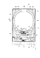
以下、パチンコ遊技機(以下、単に「パチンコ機」という)の一実施の形態を、図面に基づいて詳細に説明する。図1はパチンコ機10の正面図であり、図2は、外枠11に対して内枠12と前面枠セット14とを開放した状態を示す斜視図である。但し、図2では便宜上、下皿ユニット13が内枠12から取り外された状態を示している。
Hereinafter, an embodiment of a pachinko gaming machine (hereinafter simply referred to as “pachinko machine”) will be described in detail with reference to the drawings. FIG. 1 is a front view of the
図1,2に示すように、パチンコ機10は、当該パチンコ機10の外殻を形成する外枠11と、この外枠11の一側部に開閉可能に支持された内枠12とを備えている。
As shown in FIGS. 1 and 2, the
内枠12の開閉軸線はパチンコ機10の正面からみてハンドル(後述する遊技球発射ハンドル18)設置箇所の反対側(図1のパチンコ機10の左側)で上下に延びるように設定されており、この開閉軸線を軸心にして内枠12が前方側に十分に開放できるようになっている。
The opening / closing axis of the
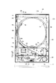
内枠12の構成を図3も用いて詳細に説明する。図3は、パチンコ機10から前面枠セット14を取り外した状態を示す正面図である(但し、図3では便宜上、遊技盤30面上の遊技領域内の構成を空白で示している)。
The configuration of the
内枠12は、大別すると、その最下部に取り付けられた下皿ユニット13と、この下皿ユニット13よりも上側の範囲で内枠12の左側の上下方向の開閉軸線を軸心にして開閉自在に取り付けられた前面枠セット14と、後述する樹脂ベース20と、この樹脂ベース20の後側に取り付けられる遊技盤30とを備えている。
The
下皿ユニット13は、内枠12に対してネジ等の締結具により固定されている。この下皿ユニット13の前面側には、下皿15と球抜きレバー17と遊技球発射ハンドル18と音出力口24が設けられている。球受皿としての下皿15は、下皿ユニット13のほぼ中央部に設けられており、排出口16より排出された遊技球が下皿15内に貯留可能になっている。球抜きレバー17は、下皿15内の遊技球を抜くためのものであり、この球抜きレバー17を図1で左側に移動させることにより、下皿15の底面の所定箇所が開口され、下皿15内に貯留された遊技球を下皿15の底面の開口部分を通して下方向外部に抜くことができる。遊技球発射ハンドル18は、下皿15よりも右方で手前側に突出して配設されている。遊技者による遊技球発射ハンドル18の操作に応じて、遊技球発射装置38によって遊技球が後述する遊技盤30の方へ打ち込まれるようになっている。遊技球発射装置38は、遊技球発射ハンドル18とセットハンドルと発射モータなどで構成されている。音出力口24は、下皿ユニット13内あるいは背面に設けられたスピーカからの音を出力するための出力口である。
The
また、前面枠セット14は、図2に示すように、内枠12に対して開閉可能に取り付けられており、内枠12と同様、パチンコ機10の正面からみて左側に上下に延びる開閉軸線を軸心にして前方側に開放できるようになっている。しかも前面枠セット14は内枠12の外側壁(リブ)12b(図3参照)内に嵌まり込むようにして取り付けられている。つまり、この前面枠セット14の側面の少なくとも一部が内枠12の外側壁(リブ)12b内に嵌まり込むようにして取り付けられているので、内枠12と前面枠セット14との隙間から異物(針状あるいは薄板状等のもの)を差し入れるなどの不正行為を防止できるようになっている。
As shown in FIG. 2, the front frame set 14 is attached to the
一方、前面枠セット14の下部(上述の下皿15の上方位置)には、遊技球の受皿としての上皿19が一体的に設けられている。ここで、上皿19は、遊技球を一旦貯留し、一列に整列させながら遊技球発射装置38の方へ導出するための球受皿である。従来のパチンコ機では前面枠セットの下方に内枠に対し開閉可能な前飾り枠が設けられ、該前飾り枠に上皿が設けられていたのであるが、本実施の形態では前飾り枠が省略され、前面枠セット14に対し直接的に上皿19が設けられている。
On the other hand, an
図3に示すように、内枠12は、外形が矩形状の樹脂ベース20を主体に構成されており、樹脂ベース20の中央部には略円形状の窓孔21が形成されている。樹脂ベース20の後側には遊技盤30が着脱可能に装着されている。遊技盤30は四角形状の合板よりなり、その周縁部が樹脂ベース20(内枠12)の裏側に当接した状態で取着されている。従って、遊技盤30の前面部の略中央部分が樹脂ベース20の窓孔21を通じて内枠12の前面側に露出した状態となっている。また、窓穴21には、2枚のガラス137(図2参照)が前後に所定間隔を隔てて取着されている。
As shown in FIG. 3, the
次に、図4を用いて遊技盤30の構成を説明する。図4は遊技盤30の構成を示す正面図である。遊技盤30は、一般入賞口31、可変入賞装置32、第1の始動口33(例えば作動チャッカ)、第2の始動口34(例えばスルーゲート)、可変表示装置ユニット35等を備えている。これらの一般入賞口31、可変入賞装置32、第1の始動口33(例えば作動チャッカ)、第2の始動口34(例えばスルーゲート)、可変表示装置ユニット35等は、遊技盤30における、ルータ加工によって形成された各貫通孔にそれぞれに配設され、遊技盤30前面側から木ネジ等により取り付けられている。前述の一般入賞口31、可変入賞装置32および第1の始動口33に遊技球が入球し、当該入球が後述する検出スイッチ(入賞口スイッチ(図示省略)、カウントスイッチ(図示省略)、作動口スイッチ224(図5参照)等)で検出され、この検出スイッチの出力に基づいて、上皿19(または下皿15)へ所定数の賞品球が払い出される。その他に、遊技盤30にはアウト口36が設けられており、各種入賞装置等に入球しなかった遊技球はこのアウト口36を通って図示しない球排出路の方へと案内されるようになっている。遊技盤30には、遊技球の落下方向を適宜分散、調整等するために多数の釘が植設されているとともに、風車37等の各種部材(役物)が配設されている。
Next, the configuration of the
可変表示装置ユニット35は、第1の始動口33への入賞をトリガとして、識別情報としての第1図柄(例えば特別図柄)を変動表示する第1図柄表示装置42と、第2の始動口34の通過をトリガとして、第2図柄(例えば普通図柄)を変動表示する第2図柄表示装置41とを備えている。
The
第2図柄表示装置41は、第2図柄用の表示部43と保留ランプ44とを有し、遊技球が第2の始動口34を通過する毎に例えば表示部43による表示図柄(普通図柄)が変動し、その変動表示が所定図柄で停止した場合に第1の始動口33が所定時間だけ作動状態となる(開放される)よう構成されている。遊技球が第2の始動口34を通過した回数は最大4回まで保留され、その保留回数が保留ランプ44にて点灯表示されるようになっている。なお、表示部43は、複数のランプの点灯を切り換えることにより変動表示される構成の他、第1図柄表示装置42(液晶表示装置)の一部で変動表示される構成等であっても良い。保留ランプ44も同様に、第1図柄表示装置42の一部で変動表示される構成等であっても良い。なお、上述した第2図柄表示装置41が本発明における普通識別情報変動表示手段に相当する。
The second
第1図柄表示装置42は液晶表示装置として構成されており、後述する表示制御装置45により表示内容が制御される。第1図柄表示装置42には、例えば左、中及び右の3つの図柄列が表示される。各図柄列は複数の図柄によって構成されており、これら図柄が図柄列毎にスクロールされるようにして第1図柄表示装置42に可変表示されるようになっている。なお本実施の形態では、第1図柄表示装置42(液晶表示装置)は例えば9.5インチサイズの大型の液晶ディスプレイを備える。可変表示装置ユニット35には、第1図柄表示装置42を囲むようにしてセンターフレーム47が配設されている。なお、上述した第1図柄表示装置42が本発明における識別情報変動表示手段に相当し、上述した表示制御装置45が本発明における表示制御手段に相当する。
The first
可変入賞装置32は、通常は遊技球が入賞できない又は入賞し難い閉状態になっており、大当たりの際に遊技球が入賞しやすい開状態と通常の閉状態とに繰り返し作動されるようになっている。より詳しくは、第1の始動口33に対し遊技球が入賞すると第1図柄表示装置42で図柄が変動表示され、その停止後の確定図柄が予め設定した特定の図柄の組合せとなったことを必要条件に特別遊技状態が発生する。そして、可変入賞装置32の大入賞口が所定の開放状態となり、遊技球が入賞しやすい状態(大当たり状態)になるよう構成されている。具体的には、所定時間の経過又は所定個数の入賞を1ラウンドとして、可変入賞装置32の大入賞口が所定回数繰り返し開放される。遊技球が第1の始動口33を通過した回数は最大4回まで保留され、その保留回数が保留ランプ46にて点灯表示されるようになっている。なお、保留ランプ46は、第1図柄表示装置42の一部で変動表示される構成等であっても良い。
The
また、遊技盤30には、遊技球発射装置38から発射された遊技球を遊技盤30上部へ案内するためのレールユニット50が取り付けられており、遊技球発射ハンドル18の回動操作に伴い発射された遊技球はレールユニット50を通じて所定の遊技領域に案内されるようになっている。レールユニット50はリング状をなす樹脂成型品(例えば、フッ素樹脂が添加されて成形されたもの)にて構成されており、内外二重に一体形成された内レール51と外レール52とを有する。
Further, the
内レール51の先端部分(図4の左上部)には戻り球防止部材53が取着されている。これにより、一旦、内レール51及び外レール52間の球案内通路から遊技盤30の上部へと案内された遊技球が再度球案内通路内に戻ってしまうといった事態が防止されるようになっている。また、外レール52には、遊技球の最大飛翔部分に対応する位置(図4の右上部:外レール52の先端部に相当する部位)に返しゴム54が取着されている。従って、所定以上の勢いで発射された遊技球は、返しゴム54に当たって跳ね返されるようになっている。外レール52の内側面には、遊技球の飛翔をより滑らかなものとするべく、つまり遊技球の摩擦抵抗を少なくするべく、長尺状をなすステンレス製の金属帯としての摺動プレート55が取着されている。
A return
内レール51及び外レール52間の球案内通路の入口には、同球案内通路の一部を閉鎖するようにして凸部57が形成されている。この凸部57は、内レール51からレールユニット50下端部にかけて略鉛直方向に設けられ、遊技領域まで至らず球案内通路内を逆流してくるファール球をファール球通路63(図3参照)に導くための役目をなす。なお、遊技盤30の右下隅部及び左下隅部は、証紙(例えば製造番号が記載されている)等のシール(図4のS1,S2)やプレートを貼着するためのスペースとなっており、この貼着スペースを確保するために、フランジ56に切欠58,59が形成されている。遊技盤30の右下隅部や左下隅部に、証紙等のシール(図4のS1,S2)を貼着することで、遊技盤30と証紙との一義性を持たせることができる。
A
次に、遊技領域について説明する。遊技領域は、レールユニット50の内周部(内外レール)により略円形状に区画形成されており、特に本実施の形態では、遊技盤30の盤面上に区画される遊技領域が従来よりもはるかに大きく構成されている。本実施の形態では、外レール52の最上部地点から遊技盤30下部までの間の距離は445mm(従来品よりも58mm長い)、外レール52の極左位置から内レール51の極右位置までの間の距離は435mm(従来品よりも50mm長い)となっている。また、内レール51の極左位置から内レール51の極右位置までの間の距離は418mmとなっている。
Next, the game area will be described. The game area is partitioned and formed in a substantially circular shape by the inner peripheral portion (inner and outer rails) of the
なお、可変表示装置ユニット35の両側に位置する第2の始動口34は、該第2の始動口34を通過した遊技球が中央の方へ寄せられるような案内機構を有している。これにより、遊技領域が左右方向に拡張されている場合であっても、遊技球を中央の第1の始動口33や可変入賞装置32の方へと案内することができ、ひいては、遊技領域が拡張されることにより遊技球が入賞しにくくなることによる興趣の低下が抑制されるようになっている。さらには、遊技領域が左右方向に拡張されていることによって、風車37、第2の始動口34、複数の釘(遊技球を中央に誘導するための誘導釘)、他の役物を種々配設することができ、可変表示装置ユニット35の左右両側の遊技領域での遊技球の挙動を一層面白くすることができるようになっている。また、遊技領域が上下方向にも拡張されていることから、さらに風車37、第2の始動口34、複数の釘、他の役物を種々配設することができ、遊技領域での上下方向の遊技球の挙動をより一層面白くすることができるようになっている。
In addition, the 2nd starting
図3の説明に戻り、前記樹脂ベース20において、窓孔21(遊技盤30)の下方には、遊技球発射装置38より発射された直後に遊技球を案内するための発射レール61が取り付けられている。発射レール61は、その後方の金属板62を介して樹脂ベース20に取付固定されており、所定の発射角度(打ち出し角度)にて直線的に延びるよう構成されている。従って、遊技球発射ハンドル18の回動操作に伴い発射された遊技球は、まずは発射レール61に沿って斜め上方に打ち出され、その後前述した通りレールユニット50の球案内通路を通じて所定の遊技領域に案内されるようになっている。
Returning to the description of FIG. 3, in the
本パチンコ機10の場合、遊技領域が従来よりも大幅に拡張されており、かかる構成下では、誘導レールの曲率を小さくせざるを得ないことから、打出球を安定化させるための工夫を要する。そこで本実施の形態では、遊技球の発射位置を低くするとともに発射レール61の傾斜角度(発射角度)を既存のものよりも幾分大きくし(すなわち発射レール61を立ち上げるようにし)、さらに発射レール61の長さを既存のものよりも長くして十分な長さの球誘導距離を確保するようにしている。これにより、遊技球発射装置38から発射された遊技球をより安定した状態で誘導レールに案内できるようにしている。この場合特に、発射レール61を、遊技球発射装置38の発射位置から遊技領域の中央位置(アウト口36)を越える位置まで延びるよう形成している。
In the case of this
また、発射レール61とレールユニット50(誘導レール)との間には所定間隔の隙間があり、この隙間より下方にファール球通路63が形成されている。従って、仮に、遊技球発射装置38から発射された遊技球が戻り球防止部材53まで至らずファール球として誘導レール内を逆戻りする場合には、そのファール球がファール球通路63を介して下皿15に排出される。因みに、本実施の形態の場合、発射レール61の長さは約240mm、発射レール先端部の隙間の長さ(発射レール61の延長線上の長さ)は約40mmである。
Further, there is a gap of a predetermined interval between the firing rail 61 and the rail unit 50 (guidance rail), and a
ファール球が誘導レール内を逆流してくる際、その多くは外レール52に沿って流れ、外レール52の下端部に到達した時点で下方に落下するが、一部のファール球は誘導レール内で暴れ、内レール51側へ跳ね上がるものもある。この際、跳ね上がったファール球は、球案内通路入口の前記凸部57に当たり、ファール球通路63に誘導される。これにより、ファール球の全てがファール球通路63に確実に案内されるようになる。これにより、ファール球と次に発射される遊技球との干渉が抑制される。
When the foul spheres flow backward in the guide rail, most of them flow along the
なお、詳しい図面の開示は省略するが、遊技球発射装置38には、前面枠セット14側の球出口(上皿19の最下流部より通じる球出口)から遊技球が1つずつ供給される。この際、本実施の形態では遊技球の発射位置を低くしたため、前面枠セット14側の球出口から前記発射位置への落差が大きくなるが、発射レール61の基端部付近にはその右側と手前側にそれぞれガイド部材65,66を設置した。これにより、前面枠セット14側の球出口から供給される遊技球が常に所定の発射位置にセットされ、安定した発射動作が実現できる。また、遊技球発射装置38には打球槌が設けられ、軸部を中心とする打球槌の回動に伴い遊技球が発射されるが、打球槌に関して軽量化が望まれている。それ故、アルミニウム等の軽金属への材料変更や軸部寸法の縮小化により打球槌の軽量化を図る一方で、十分な発射力を確保すべく、打球槌のヘッド部(軸部と反対側の端部)に重り部を設けている。これにより、十分でかつ安定した遊技球の発射が実現できる。打球槌の重り部を上方に突出して設けることにより、打球槌を容易に摘んだりひっかけたりすることができ、槌先の打球強さの調整等がし易くなるという効果がある。
Although detailed disclosure of the drawings is omitted, game balls are supplied to the
なお、図3中の符号67は上皿19に通ずる排出口であり、この排出口67を介して遊技球が上皿19に排出される。排出口67には、略水平方向の回転軸を軸心として略水平状態と略垂直状態とに変位する開閉式のシャッタ68が取り付けられている。前面枠セット14を内枠12から開放した状態(図3の状態)では、バネ等の付勢力によりシャッタ68が略水平状態から略垂直状態となり、排出口67から遊技球がこぼれ落ちないようにこの排出口67を閉鎖する。また、前面枠セット14を閉鎖した状態では、当該前面枠セット14の裏面に設けられた球通路樋69(図2参照)によりシャッタ68が押し開けられて略水平状態になり、排出口67の方へ排出された遊技球はもれなく球通路樋69を通って上皿19に排出されるようになる。従って、前飾り枠が省略され前面枠セット14に対して上皿19が直接設けられる構成とした本パチンコ機10において、前面枠セット14の開放に際し払出通路内等の遊技球がパチンコ機10外にこぼれ落ちてしまうといった不都合が防止できるようになっている。
In addition, the code |
樹脂ベース20には、窓孔21の右下部に略四角形状の小窓71が設けられている。従って、遊技盤30の右下隅部に張られた証紙などのシール(図4のS1)は、この小窓71を通じて視認できるようになっている。また、この小窓71からシール等を貼り付けることも可能となっている。
The
また、図3に示すように、内枠12の左端部には、前面枠セット14の支持機構として、支持金具81,82が取り付けられている。上側の支持金具81には図の手前側に切欠を有する支持孔83が設けられ、下側の支持金具82には鉛直方向に突出した突起軸84が設けられている。
As shown in FIG. 3,
図3に示すように、内枠12の上側には、前面枠セット14が内枠12に対して開かれたことを検出する前面枠セット開検出スイッチ90が設けられている。前面枠セット14が開かれると、前面枠セット開検出スイッチ90からホール内(パチンコ店内)用コンピュータへ出力されるようになっている。
As shown in FIG. 3, a front frame set
前面枠セット14にはその周囲(例えばコーナー部分)に各種ランプ等の発光手段が設けられている。これら発光手段は、大当たり時や所定のリーチ時等における遊技状態の変化に応じて点灯、点滅のように発光態様が変更制御され遊技中の演出効果を高める役割を果たすものである。例えば、窓部101の周縁には、LED等の発光手段を内蔵した環状電飾部102が左右対称に設けられ、該環状電飾部102の中央であってパチンコ機10の最上部には、同じくLED等の発光手段を内蔵した中央電飾部103が設けられている。本パチンコ機10では、中央電飾部103が大当たりランプとして機能し、大当たり時に点灯や点滅を行うことにより、大当たり中であることを報知する。さらに、上皿19周りにも、同じくLED等の発光手段を内蔵した上皿電飾部104が設けられている。その他、中央電飾部103の左右側方には、賞球払出し中に点灯する賞球ランプ105と所定のエラー時に点灯するエラー表示ランプ106とが設けられている。また、環状電飾部102の下端部に隣接するようにして、内枠12表面や遊技盤30表面等の一部を視認できるよう透明樹脂からなる小窓107が設けられている。この小窓107の所定箇所を平面状としているので、遊技盤30の右下隅部に貼り付けられた証紙などを、小窓107の当該平面状箇所から機械で好適に読み取ることができる。
The front frame set 14 is provided with light emitting means such as various lamps around it (for example, a corner portion). These light emitting means play a role of enhancing the effect of the game during the game by changing and controlling the light emission mode such as lighting and blinking according to the change of the game state at the time of big hit or predetermined reach. For example, at the periphery of the
また、窓部101の下方には貸球操作部120が配設されており、貸球操作部120には球貸しボタン121と、返却ボタン122と、度数表示部123とが設けられている。パチンコ機10の側方に配置された図示しないカードユニット(球貸しユニット)に紙幣やカード等を投入した状態で貸球操作部120が操作されると、その操作に応じて遊技球の貸出が行われる。球貸しボタン121は、カード等(記録媒体)に記録された情報に基づいて貸出球を得るために操作されるものであり、カード等に残額が存在する限りにおいて貸出球が上皿19に供給される。返却ボタン122は、カードユニットに挿入されたカード等の返却を求める際に操作される。度数表示部123はカード等の残額情報を表示するものである。なお、カードユニットを介さずに球貸し装置等から上皿に遊技球が直接貸し出されるパチンコ機、いわゆる現金機では貸球操作部120が不要となる。故に、貸球操作部120の設置部分に、飾りシール等が付されるようになっている。これにより、カードユニットを用いたパチンコ機と現金機との貸球操作部の共通化が図れる。
In addition, a ball
また、遊技盤30の裏面には、各種入賞口などの遊技球の通過を検出するための入賞感知機構などが設けられている。具体的には、遊技盤30表側の一般入賞口31に対応する位置には入賞口スイッチ(図示省略)が設けられ、可変入賞装置32には、特定領域スイッチ(図示省略)とカウントスイッチ(図示省略)とが設けられている。特定領域スイッチ(図示省略)は、大当たり状態で可変入賞装置32に入賞した遊技球が特定領域(大当たり状態継続を判定するための領域)に入ったことを判定するスイッチであり、カウントスイッチ(図示省略)は入賞球をカウントするスイッチである。また、第1の始動口33に対応する位置には作動口スイッチ224が設けられ、第2の始動口34に対応する位置にはゲートスイッチ(図示省略)が設けられている。なお、上述した作動口スイッチ224が本発明における入賞検出手段に相当する。
In addition, on the back surface of the
入賞口スイッチ(図示省略)及びゲートスイッチ(図示省略)は、図示しない電気配線を通じて盤面中継基板(図示省略)に接続され、さらにこの盤面中継基板(図示省略)が後述する主基板(主制御装置261)に接続されている。また、特定領域スイッチ(図示省略)及びカウントスイッチ(図示省略)は大入賞口中継基板(図示省略)に接続され、さらにこの大入賞口中継基板(図示省略)がやはり主基板に接続されている。これに対し、作動口スイッチ224は中継基板を介さずに直接主基板に接続されている。
A prize opening switch (not shown) and a gate switch (not shown) are connected to a board relay board (not shown) through electrical wiring (not shown), and this board relay board (not shown) is a main board (main control device) to be described later. 261). In addition, the specific area switch (not shown) and the count switch (not shown) are connected to a big prize opening relay board (not shown), and this big prize opening relay board (not shown) is also connected to the main board. . On the other hand, the
その他図示は省略するが、可変入賞装置32には、大入賞口を開放するための大入賞口ソレノイドと、入賞球を特定領域に導くための入賞球振分板ソレノイドが設けられ、第1の始動口33には、電動役物を開放するための作動口ソレノイドが設けられている。
Although not shown in the drawings, the variable winning
上記入賞感知機構にて各々検出された検出結果は、後述する主基板に取り込まれ、該主基板よりその都度の入賞状況に応じた払出指令(遊技球の払出個数)が払出制御基板に送信される。そして、該払出制御基板の出力により所定数の遊技球の払出が実施される。かかる場合、各種入賞口に入賞した遊技球を入賞球処理装置に一旦集め、その入賞球処理装置で入賞球の存在を1つずつ順番に確認した上で払出を行う従来方式(いわゆる証拠球方式)とは異なり、本実施の形態のパチンコ機10では、各種入賞口毎に遊技球の入賞を電気的に感知して払出が直ちに行われる(すなわち、本パチンコ機10では入賞球処理装置を廃止している)。故に、払い出す遊技球が多量にあっても、その払出をいち早く実施することが可能となる。但し、本発明に従来の「証拠球方式」を適用してもよい。
The detection results detected by the winning detection mechanism are taken into a main board, which will be described later, and a payout command (the number of game balls to be paid out) corresponding to the winning situation is transmitted from the main board to the payout control board. The Then, a predetermined number of game balls are paid out by the output of the payout control board. In such a case, a conventional method (so-called evidence ball method) in which game balls won in various winning openings are once collected in a winning ball processing device and paid out after the winning ball processing device confirms the presence of winning balls one by one in order. Unlike the above, in the
次に、本パチンコ機10の電気的構成について、図5を用いて説明する。図5は、本パチンコ機10の電気的構成を示したブロック図である。本パチンコ機10は、主制御装置261と、払出制御装置311と、発射制御装置312と、表示制御装置45と、電源装置313などを備えている。以下に、これらの装置を個別に詳細に説明する。
Next, the electrical configuration of the
主制御装置261は、主たる制御を司るCPU、遊技プログラムを記憶したROM、遊技の進行に応じた必要なデータを記憶するRAM、各種機器との連絡をとるポート、各種抽選の際に用いられる乱数発生器、時間計数や同期を図る場合などに使用されるクロックパルス発生回路等を含む主基板を具備している。
The
また、音声ランプ制御装置262は、例えば主制御装置261(主基板)又は表示制御装置45からの指示に従い音声やランプ表示の制御を司るCPUや、その他ROM、RAM、各種ポート等を含む音声ランプ制御基板を具備している。音声ランプ制御装置262上には電源中継基板266が搭載されており、後述する電源基板より供給される電源がこの電源中継基板266を介して表示制御装置45及び音声ランプ制御装置262に出力されるようになっている。
The voice
払出制御装置311、発射制御装置312及び電源装置313は周知の通り制御の中枢をなすCPUや、その他ROM、RAM、各種ポート等を含む制御基板を具備しており、払出制御装置311の払出制御基板により、賞品球や貸出球の払出が制御される。また、発射制御装置312の発射制御基板により、遊技者による遊技球発射ハンドル18の操作に従い発射モータ(図示省略)の制御が行われ、電源装置313の電源基板により、各種制御装置等で要する所定の電源電圧が生成され出力される。
The
また、電源装置313にはRAM消去スイッチ(図示省略)が設けられている。本パチンコ機10はバックアップ機能を有しており、万一停電が発生した際でも停電時の状態を保持し、停電からの復帰(復電)の際には停電時の状態に復帰できるようになっている。従って、通常手順で(例えばホールの営業終了時に)電源遮断すると電源遮断前の状態が記憶保持されることから、電源投入時に初期状態に戻したい場合には、RAM消去スイッチを押しながら電源を投入することとしている。
The
パチンコ機10の主制御装置261には、演算装置である1チップマイコンとしてのCPU501が搭載されている。CPU501には、該CPU501により実行される各種の制御プログラムや固定値データを記憶したROM502と、そのROM502内に記憶される制御プログラムの実行に際して各種のデータ等を一時的に記憶するためのメモリであるRAM503と、割込回路やタイマ回路、データ送受信回路などの各種回路が内蔵されている。
The
RAM503は、パチンコ機10の電源のオフ後においても電源装置313からバックアップ電圧が供給されてデータが保持(バックアップ)できる構成となっており、RAM503には、各種のデータ等を一時的に記憶するためのメモリやエリアの他に、バックアップエリア503aが設けられている。
The
バックアップエリア503aは、停電などの発生により電源が切断された場合において、電源の再入時にパチンコ機10の状態を電源切断前の状態に復帰させるべく、電源切断時(停電発生時を含む。以下同様)のスタックポインタや、各レジスタ、I/O等の値を記憶しておくためのエリアである。バックアップエリア503aへの書き込みは、NMI割込み処理によって電源切断時に実行され、逆にバックアップエリア503aに書き込まれた各値の復帰は、電源入時(停電解消による電源入を含む。以下同様)の復電処理において実行される。なお、CPU501のNMI端子(ノンマスカブル割込端子)には、停電等の発生による電源断時に、後述する停電監視回路542から出力される停電信号S1が入力されるように構成されており、停電の発生により、停電処理(NMI割込み処理)が即座に実行される。
In the
かかるROM502及びRAM503を内蔵したCPU501には、アドレスバス及びデータバスで構成されるバスライン504を介して入出力ポート505が接続されている。入出力ポート505には、後述するRAM消去スイッチ回路643、払出制御装置311、表示制御装置45や、その他図示しないスイッチ群などが接続されている。
An input /
また、払出制御装置311は、払出モータにより賞球や貸し球の払出制御を行うものである。演算装置であるCPU511は、そのCPU511により実行される制御プログラムや固定値データ等を記憶したROM512と、ワークメモリ等として使用されるRAM513とを備えている。
The
払出制御装置311のRAM513は、前述した主制御装置261のRAM503と同様に、パチンコ機10の電源のオフ後においても電源装置313からバックアップ電圧が供給されてデータが保持(バックアップ)できる構成となっており、RAM513には、各種のデータ等を一時的に記憶するためのメモリやエリアの他に、バックアップエリア513aが設けられている。
The
バックアップエリア513aは、停電などの発生により電源が切断された場合において、電源の再入時にパチンコ機10の状態を電源切断前の状態に復帰させるべく、電源切断時のスタックポインタや、各レジスタ、I/O等の値を記憶しておくためのエリアである。このバックアップエリア513aへの書き込みは、NMI割込み処理によって電源切断時に実行され、逆にバックアップエリア513aに書き込まれた各値の復帰は、電源入時の復電処理において実行される。
The
かかるROM512及びRAM513を内蔵したCPU511には、アドレスバス及びデータバスで構成されるバスライン514を介して入出力ポート515が接続されている。入出力ポート515には、RAM消去スイッチ回路543、主制御装置261、発射制御装置312、払出モータ358aなどがそれぞれ接続されている。
An input /
発射制御装置312は、発射モータ(図示省略)による遊技球の発射を許可又は禁止するものであり、発射モータは、所定条件が整っている場合に駆動が許可される。具体的には、払出制御装置311から発射許可信号が出力されていること、遊技者が遊技球発射ハンドル18をタッチしていることをセンサ信号により検出していること、発射を停止させるための発射停止スイッチが操作されていないことを条件に、発射モータが駆動され、遊技球発射ハンドル18の操作量に応じた強度で遊技球が発射される。
The
表示制御装置45は、第1図柄表示装置42における第1図柄の変動表示と、第2図柄表示装置41における第2図柄の変動表示とを制御するものである。この表示制御装置45は、CPU521と、ROM(プログラムROM)522と、ワークRAM523と、ビデオRAM524と、キャラクタROM525と、画像コントローラ526と、入力ポート527と、2つの出力ポート528,529と、バスライン530,531とを備えている。入力ポート527の入力には主制御装置261の出力が接続され、入力ポート527の出力には、CPU521、ROM522、ワークRAM523、画像コントローラ526が接続されると共にバスライン530を介して一方の出力ポート528が接続されている。出力ポート528の出力には第2図柄表示装置41(表示部43)や、音声ランプ制御装置262が接続されている。また、画像コントローラ526にはバスライン531を介して出力ポート529が接続されており、その出力ポート529の出力には液晶表示装置である第1図柄表示装置42が接続されている。
The
表示制御装置45のCPU521は、主制御装置261から送信される表示コマンドに基づいて第1図柄表示装置42及び第2図柄表示装置41の表示を制御する。ROM522は、そのCPU521により実行される各種の制御プログラムや固定値データを記憶するためのメモリであり、ワークRAM523は、CPU521による各種プログラムの実行時に使用されるワークデータやフラグを一時的に記憶するためのメモリである。
The
ビデオRAM524は、第1図柄表示装置42に表示される表示データを記憶するためのメモリであり、このビデオRAM524の内容を書き替えることにより、第1図柄表示装置42の表示内容が変更される。キャラクタROM525は、第1図柄表示装置42に表示される図柄などのキャラクタデータを記憶するためのメモリである。画像コントローラ526は、CPU521、ビデオRAM524、出力ポート529のそれぞれのタイミングを調整してデータの読み書きに介在すると共に、ビデオRAM524に記憶される表示データを、キャラクタROM525から所定のタイミングで読み出して第1図柄表示装置42に表示させるものである。
The
また、電源装置313は、パチンコ機10の各部に電力を供給するための電源部541と、停電等による電源遮断を監視する停電監視回路542と、RAM消去スイッチ(図示省略)に接続されてなるRAM消去スイッチ回路543とを備えている。電源部541は、図示しない電源経路を通じて、主制御装置261や払出制御装置311等に対して各々に必要な動作電源を供給する。その概要としては、電源部541は、外部より供給される交流24ボルト電源を取り込み、各種スイッチやモータ等を駆部するための+12V電源、ロジック用の+5V電源、RAMバックアップ用のバックアップ電源などを生成し、これら+12V電源、+5V電源及びバックアップ電源を主制御装置261や払出制御装置311等に対して供給する。なお、発射制御装置312に対しては払出制御装置311を介して動作電源(+12V電源、+5V電源等)が供給される。
The
停電監視回路542は、停電等の発生による電源断時に、主制御装置261のCPU501及び払出制御装置311のCPU511の各NMl端子へ停電信号S1を出力するための回路である。停電監視回路542は、電源部541で交流5ボルトの電圧を監視し、この電圧が5ボルト未満になった時間が例えば20ミリ秒を超えた場合に停電(電源断)の発生と判断して、停電信号S1を主制御装置261及び払出制御装置311へ出力する。この停電信号S1の出力によって、主制御装置261及び払出制御装置311は、停電の発生を認識し、停電時処理(NMI割込み処理)を実行する。
The power
なお、電源部541は、電源部541で監視している交流5ボルトが5ボルト未満となった時間が20ミリ秒を越えた後においても、かかる停電時処理の実行に充分な時間の間、制御系の駆動電圧である5ボルトの出力を正常値に維持するように構成されている。よって、主制御装置261及び払出制御装置311は、停電時処理を正常に実行し完了することができる。
In addition, even after the time when the AC 5 volts monitored by the
RAM消去スイッチ回路543は、RAM消去スイッチ(図示省略)のスイッチ信号を取り込み、そのスイッチの状態に応じて主制御装置261のRAM503及び払出制御装置311のRAM513のバックアップデータをクリアするための回路である。RAM消去スイッチが押下された際、RAM消去スイッチ回路543は、RAM消去信号S2を主制御装置261及び払出制御装置311に出力する。RAM消去スイッチが押下された状態でパチンコ機10の電源が投入されると(停電解消による電源入を含む)、主制御装置261及び払出制御装置311においてそれぞれのRAM503,613のデータがクリアされる。
The RAM erase
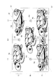
ところで、第1図柄表示装置(液晶表示装置)42には、図6に示すように、上・中・下の3つの図柄列U,M,Dが設定されており、図柄列U,M,D毎に左図柄、中図柄、右図柄の3個ずつの図柄(第1図柄:例えば特別図柄)が横方向に変動表示される。本実施の形態では、一連の図柄は、「0」〜「9」の数字を各々付した、海中生物などの絵柄からなる主図柄SZと、貝型形状の絵図柄からなる副図柄FZとにより構成されており、数字の昇順に主図柄SZが表示されると共に各主図柄SZの間に副図柄FZが配されて一連の図柄列U,M,Dが構成されている。そして、周期性を持って主図柄SZと副図柄FZが右から左へと変動表示されるようになっている。 By the way, in the first symbol display device (liquid crystal display device) 42, as shown in FIG. 6, three symbol rows U, M, and D of upper, middle, and lower are set. For each D, three symbols (the first symbol: for example, a special symbol) of the left symbol, the middle symbol, and the right symbol are variably displayed in the horizontal direction. In the present embodiment, a series of symbols is composed of a main symbol SZ made of a picture such as a marine life and a sub-design FZ made of a shell-shaped picture, each of which is given a number from “0” to “9”. The main symbols SZ are displayed in ascending numerical order, and the sub symbols FZ are arranged between the main symbols SZ to form a series of symbol rows U, M, and D. The main symbol SZ and the sub symbol FZ are variably displayed from right to left with periodicity.
かかる場合、上図柄列Uおよび中図柄列Mにおいて、上記一連の図柄が昇順(すなわち、主図柄SZの番号が増える順)に表示され、下図柄列Dにおいて、上記一連の図柄が降順(すなわち、主図柄SZの番号が減る順)に表示される。そして、第1の始動口33への入賞に基づいて一連の図柄列U,M,Dの変動表示が開始され、そして、上図柄列U→下図柄列D→中図柄列Mの順に変動表示が停止し、その停止時に第1図柄表示襲置42上の5つの有効ライン、すなわち左ラインL1、中ラインL2、右ラインL3、右上がりラインL4、左上がりラインL5の何れかで主図柄SZが大当たり図柄の組合せ(本実施の形態では、同一の主図柄SZの組合せ)で揃えば大当たりとして特定遊技動画(特別遊技動画)が表示されるようになっている。
In such a case, in the upper symbol row U and the middle symbol row M, the series of symbols is displayed in ascending order (that is, in the order of increasing the number of the main symbol SZ), and in the lower symbol row D, the series of symbols is in descending order (that is, , In order of decreasing the number of the main symbol SZ). Then, based on the winning at the first starting port 33, a series of variable symbol U, M, D display is started, and the variable symbol is displayed in the order of upper symbol column U → lower symbol column D → middle symbol column M. Is stopped, and at the time of the stop, the main symbol SZ is displayed on any of the five effective lines on the first
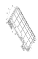
次に、本実施例のパチンコ機10のさらなる特徴部分の構成について、図7〜図14を用いて説明する。図7は主制御装置261の構成を示す分解斜視図である。図8は作動口スイッチ224が接続される主制御装置261の斜視図である。図9は上下ケース410,420の閉じる前の状態を示す斜視図である。図10は取付部材440を取り付けた状態の主制御基板400の斜視図である。図11は取付部材440の斜視図である。図12は下ケース420の斜視図である。図13は取付部材440と上ケース410とを示す斜視図である。図14は下ケース420に取付部材440が位置している様子を示す斜視図である。
Next, the structure of the further characteristic part of the
主制御装置261は、パチンコ機10の遊技を主として制御する機能を備えたものであり、図7に示すように、ICや抵抗など各種の電気部品・電子部品が実装された主制御基板400(主基板とも言う)と、この主制御基板400を被包する上ケース410,下ケース420とを備えている。主制御基板400を上ケース410,下ケース420で被包することで、ケースの外部からケース内の主制御基板400に不正にアクセス(接触など)できないようにしており、不正行為の低減に一定の効果を奏している。
The
パチンコ機10は、図4に示すように、一般入賞口31、第1の始動口33(例えば作動チャッカ)などが所定箇所に配置された遊技盤30を備えている。例えば、第1の始動口33は、当該第1の始動口33への遊技球の入球を検出する作動口スイッチ224(図5参照)を備えている。
As shown in FIG. 4, the
図8に示すように、この作動口スイッチ224は、接続ケーブル430を介して電気的に主制御基板400に接続されるようになっている。具体的には、作動口スイッチ224の接続ケーブル430での主制御基板400側のコネクタ432は、主制御基板400のコネクタ402に挿入可能となっている。
As shown in FIG. 8, the
図7に示すように、上ケース410は、当該上ケース410および下ケース420により形成される内部空間に収納された状態における主制御基板400のコネクタ402に対応する箇所に、接続ケーブル430の主制御基板400側のコネクタ432が挿入可能な挿入開口部412を備えている。
As shown in FIG. 7, the
図7に示すように、さらに、主制御基板400におけるコネクタ402を含む所定領域には、取付部材440が取り付けられている。この取付部材440は、主制御基板400のコネクタ402が挿入可能な開口部442(図11参照)を有している。この開口部442は、当該開口部442に主制御基板400のコネクタ402を挿入させた状態でこの主制御基板400のコネクタ402の外周に当接する当接部444を備えている。
As shown in FIG. 7, an
図7に示すように、主制御基板400の取付部材440が取り付けられる面(図7において見える面)は、電気部品・電子部品が実装される実装面JMであり、主制御基板400の取付部材440が取り付けられる面とは裏側の面(図7において見えない側の面)は、電気部品・電子部品の端子などが半田付けされる半田面HMである。
As shown in FIG. 7, the surface on which the mounting
図7に示すように、主制御基板400は、その実装面が上ケース410の内部に対向する状態で、上ケース410に取り付けられる。なお、主制御基板400には、図9に示すように取付部材440が取り付けられた状態で、上ケース410に取り付けられる。このように主制御基板400が内部に取り付けられた上ケース410の一端側(図9を見た状態で上ケース410の左側の長辺の端部)と、下ケース420の他端側(図9を見た状態で下ケース420の右側の長辺の端部)とを嵌合させた状態で、上ケース410を矢印YA方向にスライド移動させるか、下ケース420を矢印YB方向にスライド移動させるか、あるいは双方ともスライド移動させることで、主制御基板400を上ケース410および下ケース420で被包した状態とすることができるようになっている。
As shown in FIG. 7, the
図10,図11に示すように、取付部材440は、当該取付部材440が取り付けられた主制御基板400が何れのパチンコ機(遊技機)の種類のものかを識別するための認識情報を視認可能に形成した認識部460を備えている。また、認識部460は、取付部材440に一体的に形成されたものとしている。また、認識部460は例えば透明部材としている。
As shown in FIGS. 10 and 11, the
例えば、この認識情報としては、パチンコ機の名称や機種などパチンコ機に関する文字情報などが挙げられ、認識部460の表面に文字情報を凸状に形成している。このように透明部材たる認識部460の表面に凸状形成で文字情報(認識情報)を設けているので、文字情報(認識情報)を読み取れるだけでなく、この認識部460の裏面側も透視することができる。
For example, the recognition information includes character information related to the pachinko machine such as the name and model of the pachinko machine, and the character information is formed in a convex shape on the surface of the
また、図7,図8に示すように、上ケース410および下ケース420からなる被包構成は、その内部に主制御基板400を封入した状態を維持する封入維持部470(かしめ部)を備えている。この封入維持部470は、その所定箇所が破壊されることで上ケース410および下ケース420からなる被包構成の開封が可能となり、かつ、当該破壊の痕跡が残るものである。
Further, as shown in FIGS. 7 and 8, the enveloping configuration including the
以下に、封入維持部470(かしめ部)の構成について説明する。この封入維持部470(かしめ部)は、図7に示すように、取付部材440に備えられた突出棒472と、下ケース420に備えられた嵌入部422と、上ケース410に備えられた外囲部414とを備えている。
Below, the structure of the enclosure maintenance part 470 (caulking part) is demonstrated. As shown in FIG. 7, the sealing and maintaining portion 470 (caulking portion) includes a protruding
具体的には、取付部材440は、図7,図10,図11に示すように、返り部474が所定箇所に形成された突出棒472を複数本(本実施例では、例えば5本)備えている。この突出棒472は、取付部材440から立設した逆L字状の形状となっており、その先端部に返り部474が形成されている。
Specifically, as shown in FIGS. 7, 10, and 11, the
取付部材440が取り付けられた主制御基板400は、前述したように上ケース410に取り付けられるようになっている。また、下ケース420には、取付部材440の突出棒472が嵌入され、かつ、その突出棒472の返り部474の戻りを阻止する阻止部424を有する嵌入部422を備えている。この嵌入部422は、阻止部424が載置される底部422aと、この底部422aの両端から立設された両壁部422bと、この底部422aの奥側端から立設された奥板部422cとを備えている。この両壁部422bの内側には溝部422dが形成されている。
The
この阻止部424としては、図7,図12に示すように、平面視でΠ字状(パイ字状)のピンなどが挙げられる。つまり、このピンなる阻止部424は、図12に示すように、そのΠ字状の2本の棒部424aの先端部それぞれに掛部424bが形成され、そのΠ字状の1本の渡し部424c(前記の2本の棒部を備えた板状体)の両端それぞれが嵌入部422の両壁部422bの溝部422dに嵌め込まれ、矢印YAおよび矢印YBの方向に移動しないようにしたものが挙げられる。
As the blocking
図7,図13に示すように、上ケース410は、その所定箇所(図7では、上ケース410の左側の長辺の端部)に、下ケース420の嵌入部422を覆う外囲部414を備えている。
As shown in FIGS. 7 and 13, the
図14に示すように、取付部材440の突出棒472が下ケース420の嵌入部422に挿入されると、この突出棒472の返り部474が嵌入部422の阻止部424に嵌め込まれた状態となり、取付部材440を矢印YAおよび矢印YBの方向に移動させることができないようになっている。つまり、取付部材440は上ケース410に取り付けられており、上ケース410を下ケース420に対して矢印YAおよび矢印YBの方向に移動させることができないようになっており、上ケース410および下ケース420からなる被包機構を開封できないようになっている。
As shown in FIG. 14, when the protruding
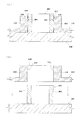
次に、主制御基板400のコネクタ402の外周と、取付部材440の開口部442に設けられた当接部444との当接状態などについて、図15を用いて説明する。図15(a)は、図10に示したA−A線断面図であり、図15(b)は、取付部材440を主制御基板400に取り付ける際の主制御基板400のコネクタ402と取付部材440の開口部442などを示す断面図である。
Next, the contact state between the outer periphery of the
図15に示すように、主制御基板400のコネクタ402の外周には周回凹部404が形成されている。つまり、主制御基板400のコネクタ402の外周には、それを一周するように周回凹部404が形成されている。なお、主制御基板400のコネクタ402の外周の必要箇所にのみ周回凹部404を形成するようにしてもよい。
As shown in FIG. 15, a
図15に示すように、取付部材440の開口部442は、主制御基板400のコネクタ402を挿入可能な大きさとしており、主制御基板400のコネクタ402の外周と取付部材440の開口部442との間の隙間を無くしたいという観点から言えば、取付部材440の開口部442が主制御基板400のコネクタ402の外周に当接して挿入される程度がより好ましい。当接部444は、取付部材440の開口部442に設けられたものであり、取付部材440から立設された、主制御基板400のコネクタ402の外周を囲うべく形成された壁部446と、この壁部446の内周側に形成された、コネクタ402の外周の周回凹部404に嵌合する周回凸部448とを備えている。
As shown in FIG. 15, the
図15(b)に示すように、取付部材440の開口部442に主制御基板400のコネクタ402を挿入させるようにして、取付部材440を主制御基板400に取り付け、図15(a)に示す状態に取り付ける。図15(a)に示すように、主制御基板400のコネクタ402の外周は、その全周にわたって取付部材440の開口部442の当接部444が当接している。つまり、主制御基板400のコネクタ402の外周の周回凹部404に、その全周にわたって取付部材440の開口部442の当接部444の周回凸部448が当接している。したがって、周回凹部404および周回凸部448により、取付部材440の開口部442と主制御基板400のコネクタ402との間の隙間が塞がれた状態となっている。
As shown in FIG. 15B, the
なお、上述した主制御基板400(主基板)が本発明における制御手段に相当し、上述した上ケース410および下ケース420が本発明における被包手段に相当し、上述した上ケース410が本発明における第1ケースに相当し、上述した下ケース420が本発明における第2ケースに相当し、上述した作動口スイッチ224が本発明における被対象品に相当し、上述したコネクタ402が本発明における接続部に相当し、上述した認識部460が本発明における認識手段に相当し、上述した封入維持部470が本発明における封入維持手段に相当する。
The above-described main control board 400 (main board) corresponds to the control means in the present invention, the above-described
ここで、本パチンコ機10の主制御基板400を上ケース410および下ケース420からなる被包構成に収納する手順と、その上ケース410および下ケース420から主制御基板400を取り出す手順とを、以下に順番に説明する。
Here, a procedure for storing the
まず、主制御基板400を上ケース410および下ケース420からなる被包構成に収納する手順について説明する。図11に示す取付部材440を、図10に示すように主制御基板400に取り付ける。つまり、主制御基板400のコネクタ402を含む所定領域に取付部材440を取り付ける。
First, a procedure for housing the
図15を用いて説明したように、図11に示す取付部材440の主制御基板400への取り付け状態において、周回凹部404および周回凸部448により、取付部材440の開口部442と主制御基板400のコネクタ402との間の隙間が塞がれた状態となっている。
As described with reference to FIG. 15, in the mounting state of the mounting
続いて、図10に示した取付部材440付きの主制御基板400を、図7に示すように、その実装面JMが上ケース410の内部に対向するようにして上ケース410に取り付ける。そして、このように主制御基板400が取り付けられた上ケース410のコネクタ402側の長辺端部を、図9に示すように、下ケース420の封入維持部470とは反対側の長辺端部に合わせて、矢印YAの方向に上ケース410をスライド移動させて、図8に示すような被覆状態とする。つまり、主制御基板400を上ケース410および下ケース420内に被覆した状態する。
Subsequently, the
図8に示した被覆状態となれば、図14に示すように、取付部材440の突出棒472の返り部474が下ケース420の嵌入部422の阻止部424(ピン)に嵌合された状態となり、封入維持部470の所定箇所を破壊しなければ、上ケース410と下ケース420の開封ができない状態となり、不正行為の防止に一定の効果を奏する状態となっている。なお、この状態の主制御装置261(主制御基板400を上ケース410と下ケース420で被包した状態のもの)がパチンコ機10の裏面側の所定位置に配置されるようになっている。
In the covering state shown in FIG. 8, as shown in FIG. 14, the
次に、上ケース410および下ケース420で被包された主制御基板400を取り出す手順について、図16も用いて説明する。図16は封入維持部470の破壊後状態を示す図である。
Next, a procedure for taking out the
前述したように封入維持部470の所定箇所を破壊しなければ、上ケース410と下ケース420の開封ができないため、図12に示すように、封入維持部470の第1の破壊箇所SAと第2の破壊箇所SBとを切断破壊する。なお、第2の破壊箇所SBは、図12に示すように2箇所ある。
As described above, since the
封入維持部470の第1の破壊箇所SAと第2の破壊箇所SBとを切断破壊することで、図16に示すように、上ケース410を矢印YBの方向にスライド移動させるか、下ケース420を矢印YAの方向にスライド移動させることにより、上ケース410と下ケース420を開封できる。図16に示すように、封入維持部470の第1の破壊箇所SAの破壊痕跡HAと、封入維持部470の2箇所の第2の破壊箇所SBの破壊痕跡HBとが残っていることがわかる。また、上ケース410の方には、封入維持部470の切断された一部HCがそのまま付いた状態となっていることがわかる。
As shown in FIG. 16, the
このままでは、上ケース410に主制御基板400が取り付けられたままであるので、図13に示すように、封入維持部470の第3の破壊箇所SCを切断破壊する。なお、図13では、図16に示した封入維持部470の切断された一部HCを削除した状態を図示している。
If this is the case, the
そして、主制御基板400の上ケース410に対する取り付けを解除、例えば、上ケース410にネジ止めされていた主制御基板400をそのネジ止めを解除することで、主制御基板400をケースから取り外す。なお、図12に示した阻止部424(ピン)は、次のかしめのために使いまわしするようにしている。
Then, the
パチンコ機10が設置される遊技店(ホール)の店員など、パチンコ機10の正当使用者は、封入維持部470(かしめ部)の破壊痕跡(第1〜第3の破壊箇所SA〜SC)に基づいて、不正開封があったか否かを確認でき、不正行為の発見に顕著な効果を奏する。
A legitimate user of the
上述したように、本実施例のパチンコ機10によれば、当該パチンコ機10についての少なくとも一部の機能を制御する主制御基板400と、この主制御基板400を被包する上ケース410と下ケース420とからなる被包構成と、主制御基板400とは別体で、当該主制御基板400に接続ケーブル430を介して電気的に接続される作動口スイッチ224と、を備え、主制御基板400は、接続ケーブル430の主制御基板400側のコネクタ432が接続可能なコネクタ402を備え、上ケース410は、当該上ケース410の内部に収納された状態における主制御基板400のコネクタ402に対応する箇所に、接続ケーブル430の主制御基板400側のコネクタ432が挿入可能な挿入開口部412を備え、主制御基板400におけるコネクタ402を含む所定領域に取り付けられる部材であって、主制御基板400のコネクタ402が挿入可能な開口部442を有し、かつ、その開口部442にコネクタ402を挿入させた状態で当該コネクタ402の外周に当接する当接部444が開口部442に設けられた取付部材440を備えているので、主制御基板400に取り付けられた取付部材440は、その当接部444が主制御基板400のコネクタ402の外周に当接させた状態とすることができ、主制御基板400のコネクタ402の外周を取付部材440の当接部444で隙間無く覆うことができ、上ケース410と下ケース420内に収納された主制御基板400に不正にアクセスすることが困難となり、主制御基板400に対する不正行為を防止することができる。しかも、上ケース410の挿入開口部412や主制御基板400のコネクタ402などを硬化材料で固めて封止するようなことはしないので、上ケース410と下ケース420からなる被包構成からの主制御基板400の取り出しも簡単に行うことができるし、何らかの部品を破壊するようなこともない。その結果、主制御基板400に対する不正対策に優れ、かつ、主制御基板400の取り出しの利便性を確保できるパチンコ機(遊技機)を提供できる。
As described above, according to the
また、主制御基板400のコネクタ402の外周には所定の周回凹部404が形成され、当接部444は、取付部材440から立設された、主制御基板400のコネクタ402の外周を囲うような壁部446と、この壁部446の内周側に形成された、コネクタ402の外周の周回凹部404に嵌合する周回凸部448とを備えているので、主制御基板400に取り付けられた取付部材440は、その当接部444が主制御基板400のコネクタ402の外周に当接させた状態とすることができる。つまり、当接部444たる壁部446の内周側でその内周側を一周する周回凸部448が、主制御基板400のコネクタ402の外周でその外周回りを一周する周回凹部404に嵌合された状態となるので、主制御基板400のコネクタ402の外周を取付部材440の当接部444で隙間無く覆うことができ、上ケース410と下ケース420からなる被包構成内に収納された主制御基板400に不正にアクセスすることが困難となり、主制御基板400に対する不正行為を防止することができる。しかも、上ケース410の挿入開口部412や主制御基板400のコネクタ402などを硬化材料で固めて封止するようなことはしないので、被包構成からの主制御基板400の取り出しも簡単に行うことができるし、何らかの部品を破壊するようなこともない。その結果、主制御基板400に対する不正対策に優れ、かつ、主制御基板400の取り出しの利便性を確保できるパチンコ機を提供できる。
Further, a predetermined
また、取付部材440は、当該取付部材440が取り付けられた主制御基板400が何れのパチンコ機(遊技機)の種類のものかを識別するための認識情報を視認可能に形成した認識部460を備えているので、取付部材440の認識部460を見ることで、主制御基板400が何れのパチンコ機(遊技機)の種類のものであるかを知ることができ、種類の異なるパチンコ機(遊技機)に誤って主制御基板400が取り付けられることを低減できる。
In addition, the
また、主制御基板400を被覆するケース(上ケース410や下ケース420)に、主制御基板400が何れのパチンコ機(遊技機)の種類のものかを識別するための認識情報を視認可能に形成する必要がないので、機種ごとに個別の専用ケースを用意する必要がなく、ケースを異機種間にわたって共用することができ、パチンコ機の受注を受けてからでなければケースを生産できないという製造制約を解消できる。つまり、ある機種のケース(前記の認識情報が形成されたケース)を作り置きし、その作り置き分について販売できなければ、不必要に在庫を抱えることになり、無駄になってしまうことから、従来では受注後にケース製造するという制約下で製造を行わなければならなかったが、本実施例ではそのような必要がなくなり、ケースの作り置きしておいても別機種で使用可能であり、無駄になってしまうこともないし、受注生産に起因する作業効率の低下、つまり、受注があってからケース製造をすることによって生じるケース製造の遅れに基づく作業効率の低下を改善できる。
In addition, recognition information for identifying which pachinko machine (gaming machine) type the
また、認識部460は、取付部材440に一体的に形成されたものとしているので、取付部材440に対して認識部460を取り替えることを困難にでき、取付部材440に対して認識部460を入れ替えるという不正行為を低減できる。
In addition, since the
また、認識部460は透明部材としているので、この認識部460の裏面側に位置する主制御基板400の所定領域も見ることができる。つまり、透明な認識部460としているので、その背後に位置する主制御基板400の所定部分も見ることができ、認識部460の背後側に不正行為を行うことが困難となり、不正行為を低減できる。
Further, since the
また、上ケース410と下ケース420からなる被包構成は、その内部に主制御基板400を封入した状態を維持する封入維持部470を備え、封入維持部470は、その所定箇所が破壊されることで上ケース410と下ケース420の開封が可能となり、かつ、当該破壊の痕跡が残るものであるとしているので、封入維持部470の所定箇所を破壊しなければ上ケース410と下ケース420を開封することができないので、主制御基板400に対する不正行為を低減できる。また、封入維持部470の所定箇所を破壊して上ケース410と下ケース420を開封し、この上ケース410と下ケース420で形成される内部空間に収納されていた主制御基板400に不正行為を行ったとしても、当該破壊の痕跡に基づいて不正行為があったことやそのおそれを知ることができ、主制御基板400に対する不正行為を低減できる。
In addition, the enveloping configuration including the
また、上ケース410と下ケース420とからなる被包構成は、上ケース410と下ケース420とを取り付けた状態でそれらによって形成される内部空間に主制御基板400を収納可能とするものであり、取付部材440は、返り部474が所定箇所に形成された突出棒472を備え、取付部材440が取り付けられた主制御基板400は上ケース410に取り付けられ、下ケース420には、突出棒472が嵌入され、かつ、返り部474の戻りを阻止する阻止部424を有する嵌入部422が備えられ、上ケース410は嵌入部422を覆う外囲部414を備え、封入維持部470は、突出棒472と嵌入部422と外囲部414とで構成されている。したがって、封入維持部470の外囲部414を破壊しなければ上ケース410と下ケース420を開封することができないので、主制御基板400に対する不正行為を低減できる。また、封入維持部470の外囲部414を破壊して上ケース410と下ケース420を開封し、この上ケース410と下ケース420内に収納されていた主制御基板400に不正行為を行ったとしても、当該破壊の痕跡に基づいて不正行為があったことやそのおそれを知ることができ、主制御基板400に対する不正行為を低減できる。
In addition, the enveloping configuration including the
この発明は、上記実施形態に限られることはなく、下記のように変形実施することができる。 The present invention is not limited to the above-described embodiment, and can be modified as follows.
(1)上述した実施例では、図15に示すように、主制御基板400のコネクタ402の外周には周回凹部404を形成し、当接部444は、取付部材440から立設された、主制御基板400のコネクタ402の外周を囲うべく形成された壁部446と、この壁部446の内周側に形成された、コネクタ402の外周の周回凹部404に嵌合する周回凸部448とを備えたものとしているが、図17に示すように、主制御基板400のコネクタ402の外周には所定の周回凸部448を形成し、当接部444は、取付部材440から立設された、主制御基板400のコネクタ402の外周を囲うような壁部446と、この壁部446の内周側に形成された、コネクタ402の外周の周回凸部448に嵌合する周回凹部404とを備えるようにしてもよい。このようにした場合でも、前述の実施例と同様の効果を得ることができる。
(1) In the above-described embodiment, as shown in FIG. 15, the
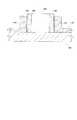
(2)上述した実施例では、図15に示すように、主制御基板400のコネクタ402の外周には周回凹部404を形成し、当接部444は、取付部材440から立設された、主制御基板400のコネクタ402の外周を囲うべく形成された壁部446と、この壁部446の内周側に形成された、コネクタ402の外周の周回凹部404に嵌合する周回凸部448とを備えたものとしているが、図18に示すように、当接部444は、取付部材440から先細りとなるように立設された、主制御基板400のコネクタ402の外周を囲うような壁部480を備えているようにしてもよい。
(2) In the above-described embodiment, as shown in FIG. 15, the
なお、図18(a)は先細り壁部480とした当接部444の概略斜視図であり、図18(b)はその(a)に示した当接部444の開口部442に主制御基板400のコネクタ402を挿入した状態の断面図であり、図18(c)はその(b)に示した当接部444を備えた取付部材440を主制御基板400のコネクタ402を挿入する際の様子を示す説明図である。
18A is a schematic perspective view of the abutting
図18(a)に示すように、取付部材440の当接部444は、先細り壁部480を備えており、この先細り壁部480により上部側および下部側の開口部442が形成される。上部側の開口部442は、下部側の開口部442よりも小さくなっており、主制御基板400のコネクタ402の外形よりも小さくなっている。図18(c)に示すように、取付部材440の開口部442に主制御基板400のコネクタ402を挿入すると、図18(b)に示すように、先細り壁部480が弾性変形して主制御基板400のコネクタ402の外周に当接した状態となり、取付部材440の開口部442と主制御基板400のコネクタ402との間の隙間が塞がれた状態となっている。
As shown in FIG. 18A, the abutting
このように構成した場合には、主制御基板400に取り付けられた取付部材440は、その当接部444が主制御基板400のコネクタ402の外周に当接させた状態とすることができる。つまり、当接部444たる先細りの壁部480の内周側が、主制御基板400のコネクタ402の外周に当接した状態となるので、主制御基板400のコネクタ402の外周を取付部材440の当接部444で隙間無く覆うことができ、上ケース410,下ケース420内に収納された主制御基板400に不正にアクセスすることが困難となり、主制御基板400に対する不正行為を防止することができる。しかも、上ケース410の挿入開口部412や主制御基板400のコネクタ402などを硬化材料で固めて封止するようなことはしないので、上ケース410,下ケース420からの主制御基板400の取り出しも簡単に行うことができるし、何らかの部品を破壊するようなこともない。その結果、主制御基板400に対する不正対策に優れ、かつ、主制御基板400の取り出しの利便性を確保できる遊技機を提供できる。
In such a configuration, the
(3)上述した実施例では、図15に示すように、主制御基板400のコネクタ402の外周には周回凹部404を形成し、当接部444は、取付部材440から立設された、主制御基板400のコネクタ402の外周を囲うべく形成された壁部446と、この壁部446の内周側に形成された、コネクタ402の外周の周回凹部404に嵌合する周回凸部448とを備えたものとしているが、図19に示すように、取付部材440の開口部442と主制御基板400のコネクタ402との間に硬化材料490を充填して硬化させるようにしてもよい。
(3) In the above-described embodiment, as shown in FIG. 15, the
なお、図19は取付部材440の開口部442と主制御基板400のコネクタ402との間に硬化材料490を充填して硬化させた様子を示す断面図である。
FIG. 19 is a cross-sectional view showing a state in which a hardening
図19に示すように、取付部材440の開口部442や主制御基板400のコネクタ402の外周には、両者を当接させる構成はなく、所定の間隔(例えば、数ミリ程度の間隔)が空いているものである。主制御基板400に取付部材440を取り付けた後に、取付部材440の開口部442と主制御基板400のコネクタ402との間に硬化材料490を充填して硬化させている。
As shown in FIG. 19, there is no configuration in which the
このように構成した場合には、主制御基板400に取り付けられた取付部材440の開口部442と主制御基板400のコネクタ402の外周との間には、硬化材料490が充填硬化されているので、主制御基板400のコネクタ402の外周を硬化材料490で隙間無く覆うことができ、上ケース410,下ケース420内に収納された主制御基板400に不正にアクセスすることが困難となり、主制御基板400に対する不正行為を防止することができる。しかも、上ケース410の挿入開口部412などを硬化材料490で固めて封止するようなことはしないので、上ケース410,下ケース420からの主制御基板400の取り出しも簡単に行うことができるし、何らかの部品を破壊するようなこともない。その結果、主制御基板400に対する不正対策に優れ、かつ、主制御基板400の取り出しの利便性を確保できる遊技機を提供できる。
In such a configuration, the
(4)上述した実施例では、上ケース410に主制御基板400を取り付けているが、下ケース420に取り付けてもよい。また、上述した実施例では、被対象品として作動口スイッチ224を採用しているが、その他の磁気センサや各種のセンサや種々の電気部品などを採用しても良い。また、上述の実施例では、主制御基板400の一箇所のコネクタ402について取付部材440の開口部442の当接部444で閉塞させることを説明したが、主制御基板400のその他の箇所のコネクタ403(図7,図10参照)および取付部材440のその他の開口部443(図11参照)について適用するようにしてもよい。
(4) In the embodiment described above, the
(5)また、上述した図12,図13に示す第1〜第3の破壊箇所SA〜SCに、ICタグ付き封印シールを貼り付け、その第1〜第3の破壊箇所SA〜SCの破壊に伴ってICタグ付き封印シールが切断(破壊)などされ、このICタグと正常に通信できないことによって不正対策を講じるようにしてもよい。 (5) Further, a seal with an IC tag is attached to the first to third destruction points SA to SC shown in FIGS. 12 and 13, and the first to third destruction points SA to SC are destroyed. Accordingly, the sealing sticker with the IC tag is cut (broken) or the like, and improper measures may be taken by not being able to communicate normally with the IC tag.
(6)本発明を各種(例えば第一種、第三種など)の遊技機に実施してもよいし、上記実施例とは異なるタイプのパチンコ機等に実施してもよい。例えば、一度大当たりすると、それを含めて複数回(例えば2回、3回)大当たり状態が発生するまで、大当たり期待値が高められるようなパチンコ機(通称、2回権利物、3回権利物と称される。)として実施してもよい。また、大当たり図柄が表示された後に、所定の領域に球を入賞されることを必要条件として特別遊技状態となるパチンコ機として実施してもよい。また、球が所定の入賞口に入ることで特別遊技状態となるパチンコ機として実施してもよい。さらに、パチンコ機以外にも、アレンジボール型パチンコ、雀球、いわゆるパチンコ機とスロットマシンとが融合した遊技機等の各種遊技機として実施するようにしてもよい。 (6) The present invention may be implemented in various (for example, first type, third type, etc.) gaming machines, or may be implemented in a pachinko machine of a type different from the above example. For example, once a big hit, a pachinko machine that raises the expected value of the big hit until a big hit state occurs (for example, two times or three times) including that (for example, a two-time right item, a three-time right item) May also be implemented. Moreover, after a jackpot symbol is displayed, it may be implemented as a pachinko machine that enters a special gaming state on the condition that a ball is won in a predetermined area. Moreover, you may implement as a pachinko machine which will be in a special game state when a ball enters a predetermined winning opening. Further, in addition to pachinko machines, various game machines such as an arrangement ball type pachinko machine, a sparrow ball, a game machine in which a so-called pachinko machine and a slot machine are integrated may be used.
なお、パチンコ機とスロットマシンとが融合した遊技機の具体例としては、複数の図柄からなる図柄列を変動表示した後に図柄を確定表示する可変表示手段を備えており、球打出用のハンドルを備えていないものが挙げられる。この場合、所定の操作(ボタン操作)に基づく所定量の遊技球の投入後、例えば操作レバーの操作に起因して図柄の変動が開始され、例えばストップボタンの操作に起因して、あるいは、所定時間経過することにより、図柄の変動が停止され、その停止時の確定図柄がいわゆる大当たり図柄であることを必要条件として遊技者に有利な大当たり状態が発生させられ、遊技者には、下部の受け皿に多量の球が払い出されるものである。 In addition, as a specific example of a gaming machine in which a pachinko machine and a slot machine are fused, a variable display means for displaying a fixed symbol after displaying a variable symbol row consisting of a plurality of symbols is provided, and a handle for launching a ball is provided. What is not provided. In this case, after inserting a predetermined amount of game balls based on a predetermined operation (button operation), for example, the variation of the symbol is started due to the operation of the operation lever, for example, due to the operation of the stop button, or the predetermined amount With the passage of time, the fluctuation of the symbol is stopped, and a jackpot state advantageous to the player is generated on the condition that the confirmed symbol at the time of stoppage is a so-called jackpot symbol. A lot of balls are paid out.
以上のように、この発明は、パチンコ機やスロットマシン等の遊技機に適している。 As described above, the present invention is suitable for gaming machines such as pachinko machines and slot machines.
224 …作動口スイッチ(被対象品)
400 …主制御基板(制御手段)
402 …コネクタ
410 …上ケース(被包手段、第1ケース)
412 …挿入開口部
420 …下ケース(被包手段、第2ケース)
430 …接続ケーブル
432 …コネクタ
440 …取付部材
442 …開口部
444 …当接部
224 ... Actuator switch (target product)
400 ... main control board (control means)
402 ...
412 ...
430 ...
Claims (1)
前記制御装置は、
接続ケーブルの接続部が接続されるコネクタと、所定の電気部品とが前面に搭載された制御基板と、
該制御基板を収容する部材であって、前記コネクタを外部に露出させるコネクタ露出部が形成されており前記制御基板の前面側に位置する前側部材と、前記制御基板の後面側に位置する後側部材とを有する基板ボックスと、
該基板ボックスの前記前側部材と前記制御基板との間に配置される部材であって、前記制御基板の前面のうち前記前側部材のコネクタ露出部に臨む領域を覆う覆い部と、該覆い部に対し前記コネクタの外形に倣う形状に形成され前記コネクタが挿入される開口部と、第1係合部とを有する取付部材と、
該取付部材の第1係合部に係合する第2係合部を有する部材であって、前記後側部材に形成された空間に収納される阻止部材とを備え、
前記第1及び第2係合部を係合させることにより前記制御装置が封印状態とされることを特徴とする遊技機。
In a gaming machine equipped with a control device for controlling games,
The controller is
A control board on which a connector to which a connection portion of a connection cable is connected and a predetermined electrical component are mounted on the front surface;
A member that accommodates the control board, wherein a connector exposed portion that exposes the connector to the outside is formed, and a front member that is located on the front side of the control board and a rear side that is located on the rear side of the control board A substrate box having a member;
A cover member that is disposed between the front member of the board box and the control board, and that covers a region of the front surface of the control board that faces the connector exposed portion of the front member; and On the other hand, an attachment member that is formed in a shape that follows the outer shape of the connector and that has an opening into which the connector is inserted, and a first engagement portion;
A member having a second engaging portion that engages with the first engaging portion of the mounting member, and a blocking member housed in a space formed in the rear member,
A gaming machine, wherein the control device is sealed by engaging the first and second engaging portions.
Priority Applications (1)
| Application Number | Priority Date | Filing Date | Title |
|---|---|---|---|
| JP2014146967A JP2014223473A (en) | 2014-07-17 | 2014-07-17 | Game machine |
Applications Claiming Priority (1)
| Application Number | Priority Date | Filing Date | Title |
|---|---|---|---|
| JP2014146967A JP2014223473A (en) | 2014-07-17 | 2014-07-17 | Game machine |
Related Parent Applications (1)
| Application Number | Title | Priority Date | Filing Date |
|---|---|---|---|
| JP2012180150A Division JP2012213662A (en) | 2012-08-15 | 2012-08-15 | Game machine |
Related Child Applications (1)
| Application Number | Title | Priority Date | Filing Date |
|---|---|---|---|
| JP2016108972A Division JP6388003B2 (en) | 2016-05-31 | 2016-05-31 | Game machine |
Publications (1)
| Publication Number | Publication Date |
|---|---|
| JP2014223473A true JP2014223473A (en) | 2014-12-04 |
Family
ID=52122641
Family Applications (1)
| Application Number | Title | Priority Date | Filing Date |
|---|---|---|---|
| JP2014146967A Pending JP2014223473A (en) | 2014-07-17 | 2014-07-17 | Game machine |
Country Status (1)
| Country | Link |
|---|---|
| JP (1) | JP2014223473A (en) |
Citations (2)
| Publication number | Priority date | Publication date | Assignee | Title |
|---|---|---|---|---|
| JPH10314415A (en) * | 1997-05-16 | 1998-12-02 | Sophia Co Ltd | Game machine board box |
| JP2003299849A (en) * | 2002-04-11 | 2003-10-21 | Sanyo Product Co Ltd | Game machine |
-
2014
- 2014-07-17 JP JP2014146967A patent/JP2014223473A/en active Pending
Patent Citations (2)
| Publication number | Priority date | Publication date | Assignee | Title |
|---|---|---|---|---|
| JPH10314415A (en) * | 1997-05-16 | 1998-12-02 | Sophia Co Ltd | Game machine board box |
| JP2003299849A (en) * | 2002-04-11 | 2003-10-21 | Sanyo Product Co Ltd | Game machine |
Similar Documents
| Publication | Publication Date | Title |
|---|---|---|
| JP2006149922A (en) | Game machine | |
| JP4765302B2 (en) | Game machine | |
| JP5206825B2 (en) | Game machine | |
| JP6388002B2 (en) | Game machine | |
| JP6388003B2 (en) | Game machine | |
| JP4725193B2 (en) | Game machine | |
| JP4872251B2 (en) | Game machine | |
| JP2007319216A (en) | Game machine | |
| JP4867288B2 (en) | Game machine | |
| JP2014223473A (en) | Game machine | |
| JP2012213662A (en) | Game machine | |
| JP2007000430A5 (en) | ||
| JP4839825B2 (en) | Game machine | |
| JP2005103011A (en) | Game machine | |
| JP5110188B2 (en) | Game machine | |
| JP4857622B2 (en) | Game machine | |
| JP5867544B2 (en) | Game machine | |
| JP5867543B2 (en) | Game machine | |
| JP5644840B2 (en) | Game machine | |
| JP5382065B2 (en) | Game machine | |
| JP4998625B2 (en) | Game machine | |
| JP4725194B2 (en) | Game machine | |
| JP4725195B2 (en) | Game machine | |
| JP2005103010A (en) | Game machine | |
| JP2017056265A (en) | Game machine |
Legal Events
| Date | Code | Title | Description |
|---|---|---|---|
| A131 | Notification of reasons for refusal |
Free format text: JAPANESE INTERMEDIATE CODE: A131 Effective date: 20150929 |
|
| A02 | Decision of refusal |
Free format text: JAPANESE INTERMEDIATE CODE: A02 Effective date: 20160301 |