JP2014228317A - Current sensor unit - Google Patents
Current sensor unit Download PDFInfo
- Publication number
- JP2014228317A JP2014228317A JP2013106521A JP2013106521A JP2014228317A JP 2014228317 A JP2014228317 A JP 2014228317A JP 2013106521 A JP2013106521 A JP 2013106521A JP 2013106521 A JP2013106521 A JP 2013106521A JP 2014228317 A JP2014228317 A JP 2014228317A
- Authority
- JP
- Japan
- Prior art keywords
- bus bar
- hole
- current sensor
- protruding piece
- sensor unit
- Prior art date
- Legal status (The legal status is an assumption and is not a legal conclusion. Google has not performed a legal analysis and makes no representation as to the accuracy of the status listed.)
- Granted
Links
Images


Landscapes
- Measuring Instrument Details And Bridges, And Automatic Balancing Devices (AREA)
Abstract
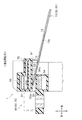
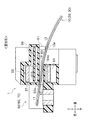
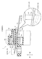
【課題】簡易な構成で電流センサにバスバ−を容易に取り付け/取り外し可能な電流センサユニットを提供する。【解決手段】第1バスバー10と、第1電流センサ50と、を備える電流センサユニット1であって、第1電流センサ50は、第1貫通孔52と、第1突出片91と、を備え、第1バスバー10は、第1差し込み孔13aを備え、第1バスバー10が第1貫通孔52に貫通した状態、かつ、第1バスバー10を傾け第1貫通孔52の開口縁部を支点として第1バスバー10を弾性変形させた状態で、第1突出片91と第1差し込み孔13aとの嵌合状態が解除され、第1バスバー10の貫通方向における移動が可能になり、第1バスバー10が第1貫通孔52に貫通した状態、かつ、第1バスバー10が弾性変形されていない状態で、第1突出片91が第1差し込み孔13aに差し込み、第1バスバー10の貫通方向における移動が規制される。【選択図】図7Provided is a current sensor unit in which a bus bar can be easily attached / detached to / from a current sensor with a simple configuration. A current sensor unit (1) includes a first bus bar (10) and a first current sensor (50), and the first current sensor (50) includes a first through hole (52) and a first protruding piece (91). The first bus bar 10 includes a first insertion hole 13a, the first bus bar 10 penetrates the first through hole 52, and the first bus bar 10 is tilted with the opening edge of the first through hole 52 as a fulcrum. In a state where the first bus bar 10 is elastically deformed, the fitted state between the first protruding piece 91 and the first insertion hole 13a is released, and the first bus bar 10 can be moved in the penetrating direction. Is inserted into the first insertion hole 13a in a state where the first bus bar 10 is not elastically deformed, and the first bus bar 10 is moved in the penetration direction. Regulated . [Selection] Figure 7
Description
本発明は、電流センサユニットに関する。 The present invention relates to a current sensor unit.
例えば、ハイブリッド車において、モータとインバータとを接続するバスバーを通電する電流値の検出に関して、磁気検知式の電流センサが知られている。磁気検知式の電流センサでは、バスバーの周囲に発生する磁界(バスバー磁界)により電流値を検出するために、電流センサにバスバーを貫通させた状態でバスバーを貫通方向において固定する必要がある。 For example, in a hybrid vehicle, a magnetic detection type current sensor is known for detecting a current value for energizing a bus bar connecting a motor and an inverter. In a magnetic detection type current sensor, in order to detect a current value by a magnetic field (bus bar magnetic field) generated around the bus bar, it is necessary to fix the bus bar in the penetrating direction with the bus bar penetrating the current sensor.
従来、電流センサにバスバーを固定する方法として、電流センサを構成する樹脂製の凸部を熱溶融させてバスバーを固定する方法が知られている(特許文献1参照)。また、バスバ−を電流センサにねじ止めすることで固定する方法が知られている(特許文献2参照)。また、インサートモールド成型によりバスバーを固定する方法が知られている(特許文献3参照)。 Conventionally, as a method of fixing the bus bar to the current sensor, a method of fixing the bus bar by thermally melting a resin convex portion constituting the current sensor is known (see Patent Document 1). A method of fixing a bus bar by screwing it to a current sensor is known (see Patent Document 2). A method of fixing a bus bar by insert molding is known (see Patent Document 3).
しかしながら、特許文献1の技術では凸部を熱溶融させる熱処理設備が必要であり、特許文献2の技術ではねじの部品点数が増加し、特許文献3の技術ではインサートモールド成型の成型難易度が高い、という不都合がある。
However, the technique of
そこで、本発明は、簡易な構成で電流センサにバスバ−を容易に取り付け/取り外し可能な電流センサユニットを提供することを課題とする。 Therefore, an object of the present invention is to provide a current sensor unit in which a bus bar can be easily attached / detached to / from a current sensor with a simple configuration.
前記課題を解決するための手段として、本発明は、弾性変形可能なバスバーと、前記バスバーの周囲に発生する磁束により前記バスバーに通電する電流量を測定する電流センサと、を備える電流センサユニットであって、前記電流センサは、前記バスバーが貫通する貫通孔と、前記貫通孔の開口から所定距離離れた位置に設けられ、前記貫通孔の貫通方向と直交すると共に前記バスバーの弾性変形方向に突出した突出片と、を備え、前記バスバーは、前記突出片が差し込まれる穴部を備え、前記バスバーが前記貫通孔に貫通した状態、かつ、前記バスバーを傾け前記貫通孔の開口縁部を支点として前記バスバーを弾性変形させた状態で、前記突出片と前記穴部との嵌合状態が解除され、前記バスバーの貫通方向における移動が可能になり、前記バスバーが前記貫通孔に貫通した状態、かつ、前記バスバーが弾性変形されていない状態で、前記突出片が前記穴部に差し込み、前記バスバーの貫通方向における移動が規制されることを特徴とする電流センサユニットである。 As means for solving the above-mentioned problems, the present invention provides a current sensor unit comprising: an elastically deformable bus bar; and a current sensor that measures an amount of current that is supplied to the bus bar by a magnetic flux generated around the bus bar. The current sensor is provided at a predetermined distance from a through hole through which the bus bar passes and an opening of the through hole, and is orthogonal to the through direction of the through hole and protrudes in the elastic deformation direction of the bus bar. The bus bar includes a hole portion into which the protruding piece is inserted, the bus bar penetrates through the through hole, and the bus bar is tilted with the opening edge of the through hole as a fulcrum. In a state where the bus bar is elastically deformed, the fitting state between the protruding piece and the hole is released, and the bus bar can be moved in the penetrating direction. An electric current characterized in that, in a state where the bus bar passes through the through hole and the bus bar is not elastically deformed, the protruding piece is inserted into the hole and movement in the through direction of the bus bar is restricted. It is a sensor unit.
このような構成によれば、バスバーが貫通孔に貫通した状態、かつ、バスバーを傾け貫通孔の開口縁部を支点としてバスバーを弾性変形させた状態で、突出片と穴部との嵌合状態が解除され、バスバーの貫通方向における移動が可能になる。
一方、バスバーが貫通孔に貫通した状態、かつ、バスバーが弾性変形されていない状態で、突出片が穴部に差し込み、バスバーの貫通方向における移動が規制される。
このようにして、突出片及び穴部を備え、そして、バスバーの弾性を利用した簡易な構成によって、電流センサにバスバ−を取り付け/取り外しできる。
According to such a configuration, in a state where the bus bar penetrates the through hole, and the bus bar is inclined and the bus bar is elastically deformed with the opening edge portion of the through hole as a fulcrum, the fitting state between the protruding piece and the hole portion Is released, and the bus bar can be moved in the penetration direction.
On the other hand, in a state where the bus bar penetrates the through hole and the bus bar is not elastically deformed, the protruding piece is inserted into the hole, and the movement of the bus bar in the penetrating direction is restricted.
In this manner, the bus bar can be attached / detached to / from the current sensor with a simple configuration that includes the protruding piece and the hole and uses the elasticity of the bus bar.
また、電流センサユニットにおいて、前記突出片は、前記貫通孔の入口側に配置されていることが好ましい。 In the current sensor unit, it is preferable that the protruding piece is disposed on the inlet side of the through hole.
このような構成によれば、突出片が貫通孔の入口側に配置されているので、バスバーを貫通孔に貫通させる際、バスバーの入口側を把持し、バスバーを貫通孔に差し込みながら、バスバーを弾性変形させることができる。すなわち、バスバーの一部分を把持しながら、バスバーの差し込みと変形とをすることができ、バスバーの取り付け作業性が向上する。 According to such a configuration, since the protruding piece is arranged on the inlet side of the through hole, when the bus bar is passed through the through hole, the bus bar is held while holding the inlet side of the bus bar and inserting the bus bar into the through hole. It can be elastically deformed. In other words, the bus bar can be inserted and deformed while gripping a part of the bus bar, and the workability of mounting the bus bar is improved.
また、電流センサユニットにおいて、前記電流センサは、前記バスバーを囲むように配置されるコアと、前記磁気を検出する磁気検出素子を搭載する板状の基板と、を備え、前記基板は、前記貫通方向において前記コアから突出し、前記突出片は、前記基板の突出側に配置されていることが好ましい。 Further, in the current sensor unit, the current sensor includes a core disposed so as to surround the bus bar, and a plate-like substrate on which the magnetic detection element for detecting the magnetism is mounted, and the substrate includes the through-hole. It is preferable that the protrusion protrudes from the core in the direction, and the protruding piece is disposed on the protruding side of the substrate.
このような構成によれば、基板が貫通方向においてコアから突出しているので、貫通孔のコアの突出側(後記する実施形態では後側)にスペースが形成される。そして、突出片が前記突出側に配置されているので、前記スペースを有効利用できる。 According to such a configuration, since the substrate protrudes from the core in the penetration direction, a space is formed on the protruding side of the core of the through hole (the rear side in the embodiment described later). And since the protrusion piece is arrange | positioned at the said protrusion side, the said space can be used effectively.
また、電流センサユニットにおいて、複数の前記バスバーと、複数の前記電流センサと、複数の前記突出片と、を備え、複数の前記バスバーと複数の前記電流センサとの誤組を防止するように、前記貫通孔の中心からの前記突出片のオフセット量は異なることが好ましい。 Further, the current sensor unit includes a plurality of the bus bars, a plurality of the current sensors, and a plurality of the protruding pieces, so as to prevent erroneous assembly of the plurality of bus bars and the plurality of current sensors. The offset amount of the protruding piece from the center of the through hole is preferably different.
このような構成によれば、貫通孔の中心からの突出片のオフセット量は異なるので、複数のバスバーと複数の電流センサとの誤組を防止できる。 According to such a configuration, since the offset amount of the protruding piece from the center of the through hole is different, it is possible to prevent erroneous assembly of the plurality of bus bars and the plurality of current sensors.
本発明によれば、簡易な構成で電流センサにバスバ−を容易に取り付け/取り外し可能な電流センサユニットを提供することができる。 According to the present invention, it is possible to provide a current sensor unit in which a bus bar can be easily attached / detached to / from a current sensor with a simple configuration.
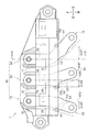
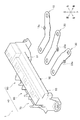
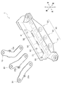
本発明の一実施形態について、図1〜図13を参照して説明する。 An embodiment of the present invention will be described with reference to FIGS.
≪電流センサユニットの構成≫
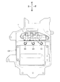
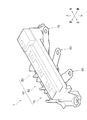
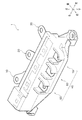
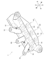
電流センサユニット1は、ハイブリッド車、電気自動車、燃料電池車等の電動車両に搭載され、三相交流を発生するインバータ101と駆動力を発生するモータ(図示しない)とを接続する3本のバスバーを含むと共に、各バスバーを通電する電流値を検出するユニットである。
≪Configuration of current sensor unit≫
The
電流センサユニット1は、3本のバスバーである第1バスバー10、第2バスバー20及び第3バスバー30と、電流センサ集合体40と、第1突出片91、第2突出片92及び第3突出片93と、を備えている。
The
<バスバー>
第1バスバー10、第2バスバー20及び第3バスバー30は、銅合金等の金属製の薄板片であって、その厚さ方向において弾性変形可能であると共に導電性を有している。第1バスバー10、第2バスバー20及び第3バスバー30は、三相交流を構成するU相、V相及びW相に対応している。第1バスバー10、第2バスバー20及び第3バスバー30は、電流センサ集合体40の後方から前方に向かって差し込まれ、電流センサ集合体40を貫通するようになっている。第1バスバー10、第2バスバー20及び第3バスバー30の後端がインバータ101側であり、前端がモータ側である。
<Bus bar>
The
<第1バスバー>
第1バスバー10は、後記する第1電流センサ50の第1貫通孔52よりも長く構成されており、第1貫通孔52に貫通装着された場合に第1貫通孔52の前後に突出するようになっている(図5、図6参照)。第1バスバー10は、差し込み側である先端側(前側)から順に、第1前突出部分11と、第1貫通孔内部分12と、第1後突出部分13と、を備えている。
<First bus bar>
The
第1貫通孔内部分12は、第1バスバー10が第1電流センサ50に所定に取り付けられた場合において、第1貫通孔52内に配置される部分である。第1前突出部分11は、第1貫通孔内部分12の前側(第1貫通孔52の出口側)で外部に突出する部分である。第1後突出部分13は、第1貫通孔内部分12の後側(第1貫通孔52の入口側)で外部に突出する部分である。
The first through-hole
第1後突出部分13には、上下方向に延びる第1差し込み孔13a(穴部)が形成されている。すなわち、第1差し込み孔13aは、第1貫通孔52の入口側に配置されている。第1差し込み孔13aは、第1突出片91が上方から差し込まれる孔であり(図7参照)、第1突出片91が第1差し込み孔13aに差し込まれると、第1バスバー10の前後方向(第1バスバー10、第1貫通孔52の貫通方向)における移動が規制されるようになっている。
The first
<第2バスバー>
第2バスバー20は、第1バスバー10と同様の構成であり、第2前突出部分21と、第2貫通孔内部分22と、第2後突出部分23と、を備えている。第2後突出部分23には、第2差し込み孔23a(穴部)が形成されている。第2差し込み孔23aは、第2突出片92が差し込まれる孔である。
<Second bus bar>
The
<第3バスバー>
第3バスバー30は、第1バスバー10と同様の構成であり、第3前突出部分31と、第3貫通孔内部分32と、第3後突出部分33と、を備えている。第3後突出部分33には、第3差し込み孔33a(穴部)が形成されている。第3差し込み孔33aは、第3突出片93が差し込まれる孔である。
<Third bus bar>
The
<電流センサ集合体>
電流センサ集合体40は、第1電流センサ50と、第2電流センサ60と、第3電流センサ70とを備え、これらが集合し一体に構成されたものである。具体的には、第1電流センサ50の第1ハウジング51(図7参照)と、第2電流センサ60の第2ハウジング61と、第3電流センサ70の第3ハウジング71とが樹脂製であって一体に形成されているので、第1電流センサ50、第2電流センサ60及び第3電流センサ70が一体で構成されている。
<Current sensor assembly>
The
第1電流センサ50は第1バスバー10に通電する電流値を検出するセンサである。第2電流センサ60は第2バスバー20に通電する電流値を検出するセンサである。第3電流センサ70は第3バスバー30に通電する電流値を検出するセンサである。
The first
<第1電流センサ>
第1電流センサ50は、第1ハウジング51と、第1コア55と、板状の基板56と、を備えている。なお、基板56は、左右方向に延びており、第1電流センサ50、第2電流センサ60及び第3電流センサ70で共有されている。
<First current sensor>
The first
<第1電流センサ−第1ハウジング>
第1ハウジング51は、樹脂製の筐体であり、その内部に第1コア55及び基板56を収容している。第1ハウジング51は、前後方向に延び第1バスバー10が前後方向に貫通する第1貫通孔52を有している。第1貫通孔52の上方に配置される第1ハウジング51の第1上壁部53は、第1貫通孔52の入口(後側開口)よりも後方に延びている。第1貫通孔52の下方に配置される第1ハウジング51の第1下壁部54は、第1貫通孔52の出口(前側開口)より前方に延びている。
<First current sensor-first housing>
The first housing 51 is a resin casing, and houses the
第1バスバー10の厚さ方向に対応する第1貫通孔52の上下高さΔT52は、第1バスバー10の厚さΔT10よりも大きく、第1バスバー10は、第1貫通孔52を斜めの状態で貫通可能となっている(図13参照)。
The vertical height ΔT52 of the first through
すなわち、第1バスバー10が前側の徐々に高くなる斜めの状態で貫通した場合、第1バスバー10は、入口の下方に配置された第1下壁部54の第1後角部54a(貫通孔の開口縁部)と、出口の上方に配置された第1上壁部53の第1前角部53aとに接触するようになっている(図13参照)。
That is, when the
<第1電流センサ−第1コア>
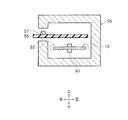
第1コア55は、前からの正面視において右方が開口したC字形を呈しており(図8参照)、第1バスバー10及び基板56を囲むように配置されている。なお、図8では、第1ハウジング51等は省略している。第1コア55は、適宜な磁性材料で形成された磁路であり、磁束密度を高めるためのものである。
<First current sensor-first core>
The
<第1電流センサ−基板>
基板56は、第1バスバー10に通電することで、第1バスバー10の周囲に発生する磁気(磁力の強さ)を検出し、第1バスバー10を流れる電流の電流値を検出するものである。基板56は、磁気を検出する第1磁気検出素子57を備えており、第1磁気検出素子57はホール効果を利用したホール素子で構成されている。そして、第1磁気検出素子57(基板56)は、磁束密度に比例した起電圧を、外部のECU(図示しない)に出力するようなっている。
<First current sensor-substrate>
The
基板56は、前後方向(第1貫通孔52の貫通方向)において、第1コア55から後方に突出している(図7参照)。これに対応して、第1ハウジング51の第1上壁部53も、第1コア55から後方に突出している。そして、第1突出片91は、基板56の突出側(後側)に配置されている。すなわち、基板56(第1上壁部53)が後方に突出したことにより、基板56(第1上壁部53)の下方かつ第1貫通孔52の後方にスペースが形成されており、そして、このスペースに第1突出片91が配置されているので、前記スペースが有効利用されている。
The
<第2電流センサ>
第2電流センサ60は、第1電流センサ50と同様の構成であり、第2ハウジング61と、第2コア65と、基板56の一部と、を備えている(図7参照)。第2ハウジング61は、前後方向に延び第2バスバー20が前後方向に貫通する第2貫通孔62を有している。
<Second current sensor>
The second
<第3電流センサ>
第3電流センサ70は、第1電流センサ50と同様の構成であり、第3ハウジング71と、第3コア75と、基板56の一部と、を備えている(図7参照)。第3ハウジング71は、前後方向に延び第3バスバー30が前後方向に貫通する第3貫通孔72を有している。
<Third current sensor>
The 3rd
<第1突出片>
第1突出片91は、第1差し込み孔13aに差し込まれる細長の円柱体であって、第1ハウジング51と一体の樹脂製である。第1突出片91は、第1貫通孔52の後方(入口側)に配置され(図7、図10参照)、第1上壁部53から下方に向かって突出している。すなわち、第1突出片91は、上下方向において、第1後角部54aと対向する第1上壁部53から下方に向かって突出している。
<First protruding piece>
The first protruding
このように第1突出片91が第1貫通孔52の入口側に配置されているので、第1バスバー10を第1電流センサ50に組み付ける場合において第1バスバー10を弾性変形させるとき、第1バスバー10を持ち変えずにそのまま湾曲させて弾性変形可能であり、組み付け作業が良好となっている。
Thus, since the
これに対して、第1突出片91が第1貫通孔52の出口側に配置されている場合、第1貫通孔52の出口側から突出する第1バスバー10を把持し弾性変形させる必要があり、手間を要してしまう。
On the other hand, when the
第1突出片91の突出長さΔL91は、第1貫通孔52の上下高さΔT52よりも長く、非変形の第1バスバー10が第1貫通孔52で斜め状態になったとしても、第1突出片91が第1差し込み孔13aに差し込まれる長さに設定されている(図13参照)。すなわち、第1バスバー10が、第1後角部54a及び第1前角部53aを支点として斜めの状態かつ非変形の状態(側面視で直線状態)において、第1突出片91が第1差し込み孔13aに差し込まれる長さに設定されている。つまり、第1貫通孔52の出口から後方に遠ざかるにつれて、第1突出片91の突出長さΔL91が長くなる関係となっている。
The projecting length ΔL91 of the first projecting
そして、第1突出片91が第1差し込み孔13aに差し込まれると、第1バスバー10の前後方向における移動が規制されるようになっている。これにより、その後に、第1バスバー10が第1電流センサ50から脱落しないようになっている。
And if the
また、第1突出片91の突出長さΔL91は、第1後角部54aを支点として第1後突出部分13を下方に屈曲させて第1バスバー10を変形させた場合(第1後突出部分13の変形時)、第1突出片91が第1差し込み孔13aから抜け、第1バスバー10が前後方向において移動可能となる長さに設定されている。すなわち、第1バスバー10の剛性が高く第1バスバー10が変形し難くなるにつれて、第1突出片91の突出長さΔL91が小さくなる関係となっている。
The protrusion length ΔL91 of the first protruding
<第2突出片>
第2突出片92は、第1突出片91と同様に、第2差し込み孔23aに差し込まれる細長の円柱体である。第2突出片91は、第2貫通孔62(図7、図10参照)の後方(入口側)に配置され、第2上壁部から下方に向かって突出している。
<Second protruding piece>
Similar to the first projecting
<第3突出片>
第3突出片93は、第1突出片91と同様に、第3差し込み孔33aに差し込まれる細長の円柱体である。第3突出片93は、第3貫通孔72(図7、図10参照)の後方(入口側)に配置され、第3上壁部から下方に向かって突出している。
<Third protruding piece>
The third
<第1突出片等のオフセット量>
図5に示すように、第1突出片91(第1差し込み孔13a)の第1貫通孔52(第1貫通孔内部分12)の第1中心軸線O52(第1貫通孔52の中心)からの第1オフセット量ΔL91と、第2突出片92(第2差し込み孔23a)の第2貫通孔62(第2貫通孔内部分22)の第2中心軸線O62からの第2オフセット量ΔL92と、第3突出片93(第3差し込み孔33a)の第3貫通孔72(第3貫通孔内部分32)の第3中心軸線O72からの第3オフセット量ΔL93とは、相互に異なっており、同一でない(ΔL91≠ΔL92≠ΔL93)。
<Offset amount of the first protruding piece, etc.>
As shown in FIG. 5, from the first central axis O52 (center of the first through hole 52) of the first through hole 52 (first through hole inner portion 12) of the first protruding piece 91 (
これにより、第1バスバー10、第2バスバー20及び第3バスバー30の間において、誤組が防止されるようになっている。すなわち、例えば、第1バスバー10は、オフセット量が一致しない第2電流センサ60及び第3電流センサ70に組み付け不能となっている。
As a result, misassembly is prevented between the
また、第1突出片91は第1中心軸線O52の右方にオフセットし、第2突出片92は第2中心軸線O62の左方にオフセットし、第3突出片93は第3中心軸線O72の左方にオフセットしている。すなわち、オフセット方向が、第1突出片91と第2突出片92第3突出片93との間で逆向きとなっており、誤組が防止されるようになっている。
The first protruding
≪電流センサユニットの組み付け方法≫
電流センサユニット1の組み付け方法について、図11〜図13を参照して説明する。以下、第1バスバー10について説明するが、第2バスバー20、第3バスバー30についても同様である。
≪Assembly method of current sensor unit≫
A method for assembling the
<差し込み開始時>
図11に示すように、第1バスバー10を前側が高くなるように斜めに傾けながら、第1バスバー10の前側を第1貫通孔52に差し込む。
<At the start of insertion>
As shown in FIG. 11, the front side of the
<変形時>
その後、第1貫通孔52から後方に突出する第1バスバー10の後側部分(主に第1後突出部分13)を、第1後角部54a(貫通孔の開口縁部)を支点として下方に屈曲させる(図12参照)。そうすると、第1バスバー10は、上向きに凸状で湾曲し、第1突出片91に引っかからずに、さらに差し込み進む。
<During deformation>
Thereafter, the rear portion of the
<非変形時>
図13に示すように、第1バスバー10を所定位置まで差し込むと、第1バスバー10の後側部分(主に第1後突出部分13)の屈曲をやめる。そうすると、第1バスバー10は、その剛性によりスプリングバックし、つまり、第1後突出部分13が上方に揺動し、第1突出片91が第1差し込み孔13aに差し込まれる。これにより、第1バスバー10は前後方向において移動不能となる。そして、第1バスバー10が第1センサ50に取り付けられる。
<When not deformed>
As shown in FIG. 13, when the
≪電流センサユニットの効果≫
このような電流センサユニット1によれば次の効果を得る。
第1突出片91は第1ハウジング51と一体成型品であり、第1バスバー10に第1差し込み孔13aを備える構成であるので、部品点数は増加しない。また、簡易な構成であるので電流センサユニット1を製造容易である。
≪Effect of current sensor unit≫
According to such a
The first projecting
第1バスバー10自体の弾性を利用して、第1バスバー10を変形/非変形させ、第1突出片91への差し込み/被差し込みを切り替えるので、第1バスバー10の脱着が容易である。すなわち、第1バスバー10と第1電流センサ50とを相互に容易に取り付け/取り外しできる。
Utilizing the elasticity of the
≪変形例≫
以上、本発明の実施形態について説明したが、本発明はこれに限定されず、例えば、次のように変更できる。
≪Modification≫
As mentioned above, although embodiment of this invention was described, this invention is not limited to this, For example, it can change as follows.
前記した実施形態では、第1バスバ−10が薄板状である構成を例示したが、その他に例えば、細長丸棒状、細長三角柱状でもよい。
In the above-described embodiment, the configuration in which the
前記した実施形態では、第1突出片91及び第1差し込み孔13aが第1貫通孔52の入口側(後側、差し込み手前側)に配置された構成を例示したが、その他に例えば、第1貫通孔52の出口側(前側、差し込み奥側)に配置された構成でもよい。
In the above-described embodiment, the configuration in which the first protruding
前記した実施形態では、第1電流センサ50が第1コア55を備える構成を例示したが、その他に例えば、第1コア55を備えないコアレス型である構成でもよい。第2電流センサ60、第3電流センサ70についても同様である。
In the above-described embodiment, the configuration in which the first
1 電流センサユニット
10 第1バスバー
13 第1後突出部分
13a 第1差し込み孔(穴部)
50 第1電流センサ
51 第1ハウジング
52 第1貫通孔
54a 第1後角部(貫通孔の開口縁部)
55 第1コア
56 基板
57 第1磁気検出素子
91 第1突出片
101 インバータ
O52 第1中心軸線
DESCRIPTION OF
50 1st current sensor 51
55
Claims (4)
前記バスバーの周囲に発生する磁束により前記バスバーに通電する電流量を測定する電流センサと、を備える電流センサユニットであって、
前記電流センサは、前記バスバーが貫通する貫通孔と、前記貫通孔の開口から所定距離離れた位置に設けられ、前記貫通孔の貫通方向と直交すると共に前記バスバーの弾性変形方向に突出した突出片と、を備え、
前記バスバーは、前記突出片が差し込まれる穴部を備え、
前記バスバーが前記貫通孔に貫通した状態、かつ、前記バスバーを傾け前記貫通孔の開口縁部を支点として前記バスバーを弾性変形させた状態で、前記突出片と前記穴部との嵌合状態が解除され、前記バスバーの貫通方向における移動が可能になり、
前記バスバーが前記貫通孔に貫通した状態、かつ、前記バスバーが弾性変形されていない状態で、前記突出片が前記穴部に差し込み、前記バスバーの貫通方向における移動が規制される
ことを特徴とする電流センサユニット。 An elastically deformable bus bar;
A current sensor for measuring a current amount energized to the bus bar by magnetic flux generated around the bus bar, and a current sensor unit comprising:
The current sensor includes a through hole through which the bus bar passes, and a protruding piece that is provided at a position away from the opening of the through hole by a predetermined distance and is orthogonal to the through direction of the through hole and protrudes in the elastic deformation direction of the bus bar. And comprising
The bus bar includes a hole portion into which the protruding piece is inserted,
In a state where the bus bar penetrates the through hole, and the bus bar is tilted and the bus bar is elastically deformed with the opening edge of the through hole as a fulcrum, the fitting state between the protruding piece and the hole portion is Released, allowing the bus bar to move in the penetration direction,
In a state where the bus bar penetrates the through hole and the bus bar is not elastically deformed, the protruding piece is inserted into the hole portion, and movement in the penetration direction of the bus bar is restricted. Current sensor unit.
ことを特徴とする請求項1に記載の電流センサユニット。 The current sensor unit according to claim 1, wherein the protruding piece is disposed on an inlet side of the through hole.
前記基板は、前記貫通方向において前記コアから突出し、
前記突出片は、前記基板の突出側に配置されている
ことを特徴とする請求項1又は請求項2に記載の電流センサユニット。 The current sensor includes a core disposed so as to surround the bus bar, and a plate-like substrate on which a magnetic detection element for detecting the magnetism is mounted,
The substrate protrudes from the core in the penetration direction;
The current sensor unit according to claim 1, wherein the protruding piece is disposed on a protruding side of the substrate.
複数の前記バスバーと複数の前記電流センサとの誤組を防止するように、前記貫通孔の中心からの前記突出片のオフセット量は異なる
ことを特徴とする請求項1から請求項3のいずれか1項に記載の電流センサユニット。 A plurality of the bus bars, a plurality of the current sensors, and a plurality of the protruding pieces,
4. The offset amount of the protruding piece from the center of the through hole is different so as to prevent erroneous assembly of the plurality of bus bars and the plurality of current sensors. 5. The current sensor unit according to item 1.
Priority Applications (1)
| Application Number | Priority Date | Filing Date | Title |
|---|---|---|---|
| JP2013106521A JP6018544B2 (en) | 2013-05-20 | 2013-05-20 | Current sensor unit |
Applications Claiming Priority (1)
| Application Number | Priority Date | Filing Date | Title |
|---|---|---|---|
| JP2013106521A JP6018544B2 (en) | 2013-05-20 | 2013-05-20 | Current sensor unit |
Publications (2)
| Publication Number | Publication Date |
|---|---|
| JP2014228317A true JP2014228317A (en) | 2014-12-08 |
| JP6018544B2 JP6018544B2 (en) | 2016-11-02 |
Family
ID=52128300
Family Applications (1)
| Application Number | Title | Priority Date | Filing Date |
|---|---|---|---|
| JP2013106521A Expired - Fee Related JP6018544B2 (en) | 2013-05-20 | 2013-05-20 | Current sensor unit |
Country Status (1)
| Country | Link |
|---|---|
| JP (1) | JP6018544B2 (en) |
Cited By (8)
| Publication number | Priority date | Publication date | Assignee | Title |
|---|---|---|---|---|
| JP2015185248A (en) * | 2014-03-20 | 2015-10-22 | 矢崎総業株式会社 | Assembly structure of current sensor and conductive member |
| WO2017002766A1 (en) * | 2015-07-02 | 2017-01-05 | Koa株式会社 | Current detection device |
| WO2019122289A1 (en) * | 2017-12-22 | 2019-06-27 | Valeo Siemens Eautomotive France Sas | Electrical connection bar |
| JP2021043102A (en) * | 2019-09-12 | 2021-03-18 | 株式会社タムラ製作所 | Current detector |
| JP2023047708A (en) * | 2021-09-27 | 2023-04-06 | 株式会社クボタ | Power conversion device |
| JPWO2024224778A1 (en) * | 2023-04-27 | 2024-10-31 | ||
| EP4425193A4 (en) * | 2021-10-29 | 2026-01-21 | Alps Alpine Co Ltd | Current sensor |
| JP7862677B2 (en) | 2023-04-27 | 2026-05-19 | アルプスアルパイン株式会社 | Current sensor |
Citations (3)
| Publication number | Priority date | Publication date | Assignee | Title |
|---|---|---|---|---|
| JP2010014477A (en) * | 2008-07-02 | 2010-01-21 | Tdk Corp | Current sensor |
| JP2010286364A (en) * | 2009-06-12 | 2010-12-24 | Yazaki Corp | Current detector assembly structure |
| JP2013027224A (en) * | 2011-07-25 | 2013-02-04 | Sumitomo Wiring Syst Ltd | Electric connection box |
-
2013
- 2013-05-20 JP JP2013106521A patent/JP6018544B2/en not_active Expired - Fee Related
Patent Citations (3)
| Publication number | Priority date | Publication date | Assignee | Title |
|---|---|---|---|---|
| JP2010014477A (en) * | 2008-07-02 | 2010-01-21 | Tdk Corp | Current sensor |
| JP2010286364A (en) * | 2009-06-12 | 2010-12-24 | Yazaki Corp | Current detector assembly structure |
| JP2013027224A (en) * | 2011-07-25 | 2013-02-04 | Sumitomo Wiring Syst Ltd | Electric connection box |
Cited By (16)
| Publication number | Priority date | Publication date | Assignee | Title |
|---|---|---|---|---|
| JP2015185248A (en) * | 2014-03-20 | 2015-10-22 | 矢崎総業株式会社 | Assembly structure of current sensor and conductive member |
| WO2017002766A1 (en) * | 2015-07-02 | 2017-01-05 | Koa株式会社 | Current detection device |
| JP2017015588A (en) * | 2015-07-02 | 2017-01-19 | Koa株式会社 | Current detection device |
| CN107710000A (en) * | 2015-07-02 | 2018-02-16 | Koa株式会社 | Current sensing means |
| WO2019122289A1 (en) * | 2017-12-22 | 2019-06-27 | Valeo Siemens Eautomotive France Sas | Electrical connection bar |
| FR3076100A1 (en) * | 2017-12-22 | 2019-06-28 | Valeo Siemens Eautomotive France Sas | ELECTRICAL CONNECTION BAR |
| JP2021043102A (en) * | 2019-09-12 | 2021-03-18 | 株式会社タムラ製作所 | Current detector |
| JP7181172B2 (en) | 2019-09-12 | 2022-11-30 | 株式会社タムラ製作所 | current detector |
| JP2023047708A (en) * | 2021-09-27 | 2023-04-06 | 株式会社クボタ | Power conversion device |
| JP7562494B2 (en) | 2021-09-27 | 2024-10-07 | 株式会社クボタ | Power Conversion Equipment |
| JP2024169676A (en) * | 2021-09-27 | 2024-12-05 | 株式会社クボタ | Power Conversion Equipment |
| JP7760676B2 (en) | 2021-09-27 | 2025-10-27 | 株式会社クボタ | Power Conversion Device |
| EP4425193A4 (en) * | 2021-10-29 | 2026-01-21 | Alps Alpine Co Ltd | Current sensor |
| JPWO2024224778A1 (en) * | 2023-04-27 | 2024-10-31 | ||
| WO2024224778A1 (en) * | 2023-04-27 | 2024-10-31 | アルプスアルパイン株式会社 | Current sensor |
| JP7862677B2 (en) | 2023-04-27 | 2026-05-19 | アルプスアルパイン株式会社 | Current sensor |
Also Published As
| Publication number | Publication date |
|---|---|
| JP6018544B2 (en) | 2016-11-02 |
Similar Documents
| Publication | Publication Date | Title |
|---|---|---|
| JP6018544B2 (en) | Current sensor unit | |
| US8237435B2 (en) | Assembling structure of current detection apparatus | |
| JP5985257B2 (en) | Current sensor | |
| JP4612554B2 (en) | Current sensor | |
| EP2619598B1 (en) | Current detecting device and attaching structure thereof | |
| CN102004180B (en) | Current sensor | |
| EP2746783B1 (en) | Current sensor | |
| KR101738781B1 (en) | Magnetic detection device and torque sensor including the same | |
| JP5403792B2 (en) | Current detector assembly structure | |
| CN103430352B (en) | battery connection assembly | |
| US8947083B2 (en) | Current detecting apparatus | |
| US8854036B2 (en) | Current detecting apparatus | |
| CN112505346A (en) | Wheel speed sensor | |
| JP2013171697A (en) | Attachment structure of temperature sensor | |
| CN105008947A (en) | Current sensor device with integrated clamping device and grounding element | |
| JP5225884B2 (en) | Assembling structure and assembling method of current detection device | |
| JP6947764B2 (en) | Liquid level detector unit | |
| JP2021139799A (en) | Current sensor | |
| JP6766930B2 (en) | Wheel speed sensor | |
| JP5873698B2 (en) | Non-contact switch | |
| JP2013164288A (en) | Current sensor | |
| JP2015108553A (en) | Current detector | |
| JP5854282B2 (en) | Current sensor and battery module | |
| JP5700745B2 (en) | Current detector assembly structure | |
| JP2006145238A (en) | Current sensor |
Legal Events
| Date | Code | Title | Description |
|---|---|---|---|
| A621 | Written request for application examination |
Free format text: JAPANESE INTERMEDIATE CODE: A621 Effective date: 20151127 |
|
| RD02 | Notification of acceptance of power of attorney |
Free format text: JAPANESE INTERMEDIATE CODE: A7422 Effective date: 20160620 |
|
| A977 | Report on retrieval |
Free format text: JAPANESE INTERMEDIATE CODE: A971007 Effective date: 20160909 |
|
| TRDD | Decision of grant or rejection written | ||
| A01 | Written decision to grant a patent or to grant a registration (utility model) |
Free format text: JAPANESE INTERMEDIATE CODE: A01 Effective date: 20160927 |
|
| A61 | First payment of annual fees (during grant procedure) |
Free format text: JAPANESE INTERMEDIATE CODE: A61 Effective date: 20160930 |
|
| R150 | Certificate of patent or registration of utility model |
Ref document number: 6018544 Country of ref document: JP Free format text: JAPANESE INTERMEDIATE CODE: R150 |
|
| R250 | Receipt of annual fees |
Free format text: JAPANESE INTERMEDIATE CODE: R250 |
|
| LAPS | Cancellation because of no payment of annual fees |