JP2014228444A - 光軸調整用の距離測定装置及び方法 - Google Patents
光軸調整用の距離測定装置及び方法 Download PDFInfo
- Publication number
- JP2014228444A JP2014228444A JP2013109263A JP2013109263A JP2014228444A JP 2014228444 A JP2014228444 A JP 2014228444A JP 2013109263 A JP2013109263 A JP 2013109263A JP 2013109263 A JP2013109263 A JP 2013109263A JP 2014228444 A JP2014228444 A JP 2014228444A
- Authority
- JP
- Japan
- Prior art keywords
- optical device
- light
- wavelength
- optical
- light intensity
- Prior art date
- Legal status (The legal status is an assumption and is not a legal conclusion. Google has not performed a legal analysis and makes no representation as to the accuracy of the status listed.)
- Granted
Links
Images


Landscapes
- Length Measuring Devices By Optical Means (AREA)
Abstract
Description
また、請求項2に記載の発明は、波長が可変な光源と、前記光源からの入射光の一部を反射し、一部を出射する端面を有する第1の光デバイスと、前記第1の光デバイスから出射された光の一部を前記光デバイスに対して反射する端面を有する第2の光デバイスと、前記第2の光デバイスの透過光強度を測定する受光器と、前記光源の波長変化に対する前記受光器の強度変動を検出する検出部を含む信号処理部とを含むことを特徴とする光デバイス端面間距離測定装置である。
T=|t|2 (3)
R=|r|2 (4)
となる。
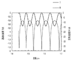
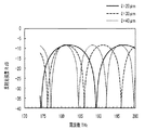
l=mλ/2 (mは整数) (5)
の条件で最大光強度が繰り返し得られる。入力光の周波数fは、
f=c/λ (c:高速) (6)
で表せるので、式(5)の条件は
f=m・c/2l (7)
となる。つまり、周波数間隔Δfとすると、
Δf=c/2l (8)
で光強度は周期性を持つことがわかる。この光強度の周期間隔は、透過光でも反射光でも同じである。
110、711 可変波長レーザ
120 第1の光デバイス
130 第2の光デバイス
121、131 光デバイス端面
101 入力光
102、104、106、108 透過光
103、105、107 反射光
701 光ファイバ
702 光導波路
712 サーキュレータ
713 光検出器
714 自動ステージ
715 ステージコントローラ
716 信号処理部
717 強度変動検出器
Claims (7)
- 波長が可変な光源と、
前記光源からの入射光の一部を反射し、一部を出射する端面を有する第1の光デバイスと、
前記第1の光デバイスから出射された光の一部を前記第1の光デバイスに対して反射する端面を有する第2の光デバイスと、
前記第1及び第2の光デバイスの入射光方向への戻り光の光強度を測定する受光器と、
前記光源の波長変化に対する前記受光器の強度変動を検出する検出部を含む信号処理部と
を含むことを特徴とする光デバイス端面間距離測定装置。 - 波長が可変な光源と、
前記光源からの入射光の一部を反射し、一部を出射する端面を有する第1の光デバイスと、
前記第1の光デバイスから出射された光の一部を前記光デバイスに対して反射する端面を有する第2の光デバイスと、
前記第2の光デバイスの透過光強度を測定する受光器と、
前記光源の波長変化に対する前記受光器の強度変動を検出する検出部を含む信号処理部と
を含むことを特徴とする光デバイス端面間距離測定装置。 - 前記検出部は、前記光源の波長変化に対する強度変動の変動周期をさらに検出することを特徴とする請求項1又は2に記載の光デバイス端面間距離測定装置。
- 前記第1の光デバイスと前記第2の光デバイスとの端面間距離を既知の量だけ変位可能な光デバイス移動装置をさらに含み、
前記検出部が、前記移動装置の移動前、および移動後における光源の波長変化に対する前記受光器の強度変動をさらに検出することを特徴とする請求項1乃至3のいずれか1項に記載の光デバイス端面間距離測定装置。 - 前記第1の光デバイス又は前記第2の光デバイスは、光ファイバであることを特徴とする請求項1乃至4のいずれか1項に記載の光デバイス端面間距離測定装置。
- 信号処理部が、波長可変光源からの出力光の波長情報を受信するステップと、
前記信号処理部が、光検出器において測定した第1の光デバイス及び第2の光デバイスの第1の反射光強度を基に、波長スイープに同期した第1の同期反射光強度を検出するステップと、
前記信号処理部が、自動ステージ上の第1の光デバイスを既知の量だけ光軸方向に移動させる移動命令をステージコントローラに送信するステップと、
前記信号処理部が、前記波長可変光源からの出力光の波長情報を受信するステップと、
前記信号処理部が、前記光検出器において測定した移動後の前記第1の光デバイス及び前記第2の光デバイスの第2の反射光強度の情報を基に、波長スイープに同期した第2の同期反射光強度を検出するステップと、
信号処理部が、前記第1の同期反射光強度及び前記第2の同期反射光強度を元に、前記第1の光デバイスと前記第2の光デバイスとの端面間距離を算出するステップと
を含むことを特徴とする光デバイス端面間距離測定方法。 - 信号処理部に、
波長可変光源からの出力光の波長情報を受信するステップと、
光検出器において測定した第1の光デバイス及び第2の光デバイスの第1の反射光強度を基に、波長スイープに同期した第1の同期反射光強度を検出するステップと、
自動ステージ上の第1の光デバイスを既知の量だけ光軸方向に移動させる移動命令をステージコントローラに送信するステップと、
前記波長可変光源からの出力光の波長情報を受信するステップと、
前記光検出器において測定した移動後の前記第1の光デバイス及び前記第2の光デバイスの第2の反射光強度の情報を基に、波長スイープに同期した第2の同期反射光強度を検出するステップと、
前記第1の同期反射光強度及び前記第2の同期反射光強度を元に、前記第1の光デバイスと前記第2の光デバイスとの端面間距離を算出するステップと
を含む光デバイス端面距離測定方法を実行させることを特徴とするプログラム。
Priority Applications (1)
| Application Number | Priority Date | Filing Date | Title |
|---|---|---|---|
| JP2013109263A JP6082313B2 (ja) | 2013-05-23 | 2013-05-23 | 光軸調整用の距離測定装置及び方法 |
Applications Claiming Priority (1)
| Application Number | Priority Date | Filing Date | Title |
|---|---|---|---|
| JP2013109263A JP6082313B2 (ja) | 2013-05-23 | 2013-05-23 | 光軸調整用の距離測定装置及び方法 |
Publications (2)
| Publication Number | Publication Date |
|---|---|
| JP2014228444A true JP2014228444A (ja) | 2014-12-08 |
| JP6082313B2 JP6082313B2 (ja) | 2017-02-15 |
Family
ID=52128409
Family Applications (1)
| Application Number | Title | Priority Date | Filing Date |
|---|---|---|---|
| JP2013109263A Expired - Fee Related JP6082313B2 (ja) | 2013-05-23 | 2013-05-23 | 光軸調整用の距離測定装置及び方法 |
Country Status (1)
| Country | Link |
|---|---|
| JP (1) | JP6082313B2 (ja) |
Cited By (2)
| Publication number | Priority date | Publication date | Assignee | Title |
|---|---|---|---|---|
| WO2018127647A1 (fr) * | 2017-01-09 | 2018-07-12 | Legrand France | Dispositif et procede de raccordement par soudure d'une premiere fibre optique a une deuxieme fibre optique |
| US11934012B2 (en) | 2021-05-17 | 2024-03-19 | Panasonic Intellectual Property Management Co., Ltd. | Optical adjustment apparatus, optical adjustment method, and optical device |
Citations (3)
| Publication number | Priority date | Publication date | Assignee | Title |
|---|---|---|---|---|
| JPS60237409A (ja) * | 1984-05-09 | 1985-11-26 | Furukawa Electric Co Ltd:The | 光フアイバ融着接続法における光フアイバ端面間隔設定方法 |
| JPH0593613A (ja) * | 1991-10-02 | 1993-04-16 | Sumitomo Electric Ind Ltd | 微小間隔測定装置及び方法 |
| JP2006266797A (ja) * | 2005-03-23 | 2006-10-05 | Anritsu Corp | 光ヘテロダイン干渉装置 |
-
2013
- 2013-05-23 JP JP2013109263A patent/JP6082313B2/ja not_active Expired - Fee Related
Patent Citations (3)
| Publication number | Priority date | Publication date | Assignee | Title |
|---|---|---|---|---|
| JPS60237409A (ja) * | 1984-05-09 | 1985-11-26 | Furukawa Electric Co Ltd:The | 光フアイバ融着接続法における光フアイバ端面間隔設定方法 |
| JPH0593613A (ja) * | 1991-10-02 | 1993-04-16 | Sumitomo Electric Ind Ltd | 微小間隔測定装置及び方法 |
| JP2006266797A (ja) * | 2005-03-23 | 2006-10-05 | Anritsu Corp | 光ヘテロダイン干渉装置 |
Cited By (3)
| Publication number | Priority date | Publication date | Assignee | Title |
|---|---|---|---|---|
| WO2018127647A1 (fr) * | 2017-01-09 | 2018-07-12 | Legrand France | Dispositif et procede de raccordement par soudure d'une premiere fibre optique a une deuxieme fibre optique |
| FR3061778A1 (fr) * | 2017-01-09 | 2018-07-13 | Legrand France | Dispositif et procede de raccordement par soudure d'une premiere fibre optique a une deuxieme fibre optique |
| US11934012B2 (en) | 2021-05-17 | 2024-03-19 | Panasonic Intellectual Property Management Co., Ltd. | Optical adjustment apparatus, optical adjustment method, and optical device |
Also Published As
| Publication number | Publication date |
|---|---|
| JP6082313B2 (ja) | 2017-02-15 |
Similar Documents
| Publication | Publication Date | Title |
|---|---|---|
| CN113566710B (zh) | 具有光学开关的测距系统 | |
| KR101209627B1 (ko) | 분광기를 기반으로 하는 광섬유센서 시스템 | |
| KR101645274B1 (ko) | 표면 측정을 위한 간섭계 거리 측정 방법, 및 상기 측정 구조 | |
| WO2018170478A1 (en) | Fmcw lidar methods and apparatuses including examples having feedback loops | |
| KR101605837B1 (ko) | 파장 가변 레이저를 이용한 광선로 검사기 | |
| JP6062104B2 (ja) | 光ファイバセンサ装置 | |
| US9810521B2 (en) | Displacement detection apparatus | |
| JP6082320B2 (ja) | 光軸調整装置及びその工程 | |
| JP2024540968A (ja) | 光ファイバ感知システムにおけるファイバ挿入損失の測定 | |
| CN101419317A (zh) | 一种基于光纤Bragg光栅的双边缘滤波器 | |
| CN107764197A (zh) | 一种光学系统轴向参数测量装置及方法 | |
| CN105806379A (zh) | 弱反射光纤布拉格光栅-珐泊腔传感器的解调系统 | |
| JP6082313B2 (ja) | 光軸調整用の距離測定装置及び方法 | |
| JP2023133433A (ja) | 変位検出装置 | |
| CN108007603A (zh) | 一种基于非对称双芯光纤的多参量分布测量系统 | |
| JP5542255B2 (ja) | 光ファイバー長さ伸縮計測・補正方法および装置 | |
| Li et al. | Large-Range and High-Sensitivity Displacement Sensing Based on Extrinsic Fabry-Perot Interferometer Assisted Microwave Photonic Filter | |
| CN101329168A (zh) | 孪生阵列Michelson光纤白光干涉应变仪 | |
| EP3715807B1 (en) | A method and an optical sensor for optically sensing a parameter of the group of temperature, humidity or mechanical stress | |
| CN106680536A (zh) | 一种高灵敏度的单保偏光纤干涉式加速度传感系统 | |
| KR20160058568A (ko) | 거울 처리된 광섬유 코일을 이용한 반사형 진동 센서 장치 | |
| US7312435B2 (en) | Determination of a physical state of an optical device | |
| US20170030802A1 (en) | Apparatus and Method for Measuring Group Velocity Delay in Optical Waveguide | |
| JP2669359B2 (ja) | 歪み測定方法及びその装置 | |
| JP5870059B2 (ja) | 距離測定装置及び距離測定方法 |
Legal Events
| Date | Code | Title | Description |
|---|---|---|---|
| A621 | Written request for application examination |
Free format text: JAPANESE INTERMEDIATE CODE: A621 Effective date: 20150901 |
|
| A131 | Notification of reasons for refusal |
Free format text: JAPANESE INTERMEDIATE CODE: A131 Effective date: 20160531 |
|
| A521 | Request for written amendment filed |
Free format text: JAPANESE INTERMEDIATE CODE: A523 Effective date: 20160801 |
|
| TRDD | Decision of grant or rejection written | ||
| A01 | Written decision to grant a patent or to grant a registration (utility model) |
Free format text: JAPANESE INTERMEDIATE CODE: A01 Effective date: 20170117 |
|
| A61 | First payment of annual fees (during grant procedure) |
Free format text: JAPANESE INTERMEDIATE CODE: A61 Effective date: 20170120 |
|
| R150 | Certificate of patent or registration of utility model |
Ref document number: 6082313 Country of ref document: JP Free format text: JAPANESE INTERMEDIATE CODE: R150 |
|
| LAPS | Cancellation because of no payment of annual fees |