JP2014232105A - Measuring plug - Google Patents
Measuring plug Download PDFInfo
- Publication number
- JP2014232105A JP2014232105A JP2014107808A JP2014107808A JP2014232105A JP 2014232105 A JP2014232105 A JP 2014232105A JP 2014107808 A JP2014107808 A JP 2014107808A JP 2014107808 A JP2014107808 A JP 2014107808A JP 2014232105 A JP2014232105 A JP 2014232105A
- Authority
- JP
- Japan
- Prior art keywords
- module
- plug body
- interconnect
- sensing
- terminal
- Prior art date
- Legal status (The legal status is an assumption and is not a legal conclusion. Google has not performed a legal analysis and makes no representation as to the accuracy of the status listed.)
- Granted
Links
Images




Classifications
-
- F—MECHANICAL ENGINEERING; LIGHTING; HEATING; WEAPONS; BLASTING
- F02—COMBUSTION ENGINES; HOT-GAS OR COMBUSTION-PRODUCT ENGINE PLANTS
- F02B—INTERNAL-COMBUSTION PISTON ENGINES; COMBUSTION ENGINES IN GENERAL
- F02B77/00—Component parts, details or accessories, not otherwise provided for
- F02B77/08—Safety, indicating, or supervising devices
- F02B77/085—Safety, indicating, or supervising devices with sensors measuring combustion processes, e.g. knocking, pressure, ionization, combustion flame
-
- G—PHYSICS
- G01—MEASURING; TESTING
- G01L—MEASURING FORCE, STRESS, TORQUE, WORK, MECHANICAL POWER, MECHANICAL EFFICIENCY, OR FLUID PRESSURE
- G01L19/00—Details of, or accessories for, apparatus for measuring steady or quasi-steady pressure of a fluent medium insofar as such details or accessories are not special to particular types of pressure gauges
- G01L19/0061—Electrical connection means
- G01L19/0084—Electrical connection means to the outside of the housing
-
- G—PHYSICS
- G01—MEASURING; TESTING
- G01L—MEASURING FORCE, STRESS, TORQUE, WORK, MECHANICAL POWER, MECHANICAL EFFICIENCY, OR FLUID PRESSURE
- G01L19/00—Details of, or accessories for, apparatus for measuring steady or quasi-steady pressure of a fluent medium insofar as such details or accessories are not special to particular types of pressure gauges
- G01L19/14—Housings
- G01L19/148—Details about the circuit board integration, e.g. integrated with the diaphragm surface or encapsulation
-
- G—PHYSICS
- G01—MEASURING; TESTING
- G01L—MEASURING FORCE, STRESS, TORQUE, WORK, MECHANICAL POWER, MECHANICAL EFFICIENCY, OR FLUID PRESSURE
- G01L23/00—Devices or apparatus for measuring or indicating or recording rapid changes, such as oscillations, in the pressure of steam, gas, or liquid; Indicators for determining work or energy of steam, internal-combustion, or other fluid-pressure engines from the condition of the working fluid
- G01L23/08—Devices or apparatus for measuring or indicating or recording rapid changes, such as oscillations, in the pressure of steam, gas, or liquid; Indicators for determining work or energy of steam, internal-combustion, or other fluid-pressure engines from the condition of the working fluid operated electrically
- G01L23/18—Devices or apparatus for measuring or indicating or recording rapid changes, such as oscillations, in the pressure of steam, gas, or liquid; Indicators for determining work or energy of steam, internal-combustion, or other fluid-pressure engines from the condition of the working fluid operated electrically by resistance strain gauges
-
- F—MECHANICAL ENGINEERING; LIGHTING; HEATING; WEAPONS; BLASTING
- F23—COMBUSTION APPARATUS; COMBUSTION PROCESSES
- F23Q—IGNITION; EXTINGUISHING-DEVICES
- F23Q7/00—Incandescent ignition; Igniters using electrically-produced heat, e.g. lighters for cigarettes; Electrically-heated glowing plugs
- F23Q7/001—Glowing plugs for internal-combustion engines
- F23Q2007/002—Glowing plugs for internal-combustion engines with sensing means
Landscapes
- Engineering & Computer Science (AREA)
- Physics & Mathematics (AREA)
- General Physics & Mathematics (AREA)
- Chemical & Material Sciences (AREA)
- Combustion & Propulsion (AREA)
- Mechanical Engineering (AREA)
- General Engineering & Computer Science (AREA)
- Measuring Fluid Pressure (AREA)
- Measuring Temperature Or Quantity Of Heat (AREA)
- Combined Controls Of Internal Combustion Engines (AREA)
Abstract
【課題】熱的過負荷から電子部品を保護する構造により、信頼性のある接続を有する圧力プラグを提供する。【解決手段】燃焼エンジン用測定プラグ100は、中空のプラグボディ102を介して電子部品116を感知モジュール104に電気的に接続するように構成される相互接続モジュール108を含む。相互接続モジュール108は、第1の端子108Cが設けられた第1の端部108Pと、第2の端子108B1が設けられた第2の端部108Dとを有する細長の支持構造108Aを含み、第1の端子108Cは、軸方向にフレキシブルな電気的結合とする。【選択図】図1A pressure plug having a reliable connection is provided by a structure for protecting an electronic component from thermal overload. A combustion engine measurement plug includes an interconnect module configured to electrically connect an electronic component to a sensing module via a hollow plug body. The interconnect module 108 includes an elongated support structure 108A having a first end 108P provided with a first terminal 108C and a second end 108D provided with a second terminal 108B1. The first terminal 108 </ b> C is electrically coupled in the axial direction. [Selection] Figure 1
Description
本発明は、測定プラグおよび測定プラグの組み立て方法に関する。より具体的には、本発明は、燃焼エンジン用のピエゾ抵抗圧力測定プラグに関する。 The present invention relates to a measurement plug and a method for assembling the measurement plug. More specifically, the present invention relates to a piezoresistive pressure measuring plug for a combustion engine.
将来におけるガソリンエンジンのための進歩的な燃焼の方針は、全体のサイクル(圧縮‐燃焼‐排出のサイクル)中に各燃焼シリンダーからの正確な圧力フィードバックの存在に依存する。これらの方針は、予混合圧縮着火(HCCI)燃焼を含むことも含まないこともあり、迅速かつ正確な圧力応答を必要とする高い圧力放出速度になり得る。 Future combustion strategies for gasoline engines in the future depend on the presence of accurate pressure feedback from each combustion cylinder during the entire cycle (compression-combustion-exhaust cycle). These strategies may or may not include premixed compression ignition (HCCI) combustion, and can result in high pressure release rates that require a quick and accurate pressure response.
ピエゾ抵抗圧力測定プラグは、特許文献1により公知である。圧力測定プラグは、燃焼側に近接して位置され得る非常に小さな感知素子を含み、それゆえ非常に高い帯域幅のセンサが実現可能である。ボンディングワイヤを用いて、感知素子は、プラグボディ内に設置されるプリント配線基板(PWB)上のセンサ電子部品と電気的に結合される。センサ電子部品は、感知モジュール上に搭載されたピエゾ抵抗素子の抵抗の変化を測定し、条件付けされた測定信号を発生させるために配置される。ボディ内部の温度により、標準部品を有する従来のPWBを使用することはできないことが知られている。その結果、信頼性の高い圧力プラグを得るためには、より高価な部品を使用する必要がある。 A piezoresistive pressure measuring plug is known from US Pat. The pressure measuring plug includes a very small sensing element that can be located close to the combustion side, so that a very high bandwidth sensor is feasible. Using the bonding wire, the sensing element is electrically coupled to sensor electronics on a printed wiring board (PWB) installed in the plug body. The sensor electronics are arranged to measure a change in resistance of a piezoresistive element mounted on the sensing module and generate a conditioned measurement signal. It is known that conventional PWB with standard parts cannot be used due to the temperature inside the body. As a result, to obtain a reliable pressure plug, it is necessary to use more expensive parts.
EP2138819A1 EP238819A1
本発明の目的は、熱的過負荷から条件付けされた電子部品を保護する構造を有する改良型の圧力プラグを提供することである。本発明の他の目的は、信頼性のある、製造するのに安価な、半自動または完全自動の生産工程により大量生産が可能な、過酷な圧力媒体に対して長寿命および/もしくは堅牢な、内燃エンジンに典型的な高い温度および振動に耐える、といった構造のうちの少なくともひとつを有する測定プラグを提供することである。 It is an object of the present invention to provide an improved pressure plug having a structure that protects conditioned electronic components from thermal overload. Another object of the present invention is an internal combustion that is reliable, inexpensive to manufacture, capable of mass production with semi-automatic or fully automatic production processes, long life and / or robust against harsh pressure media It is to provide a measuring plug having at least one of the structures that can withstand the high temperatures and vibrations typical of engines.
本発明の第1の態様によれば、この目的は、請求項1の特徴を有する測定プラグによって達成される。有利な実施例および本発明を実施する別の方法が、従属項で言及される手段によって実現され得る。 According to a first aspect of the invention, this object is achieved by a measuring plug having the features of claim 1. Advantageous embodiments and alternative ways of implementing the invention can be realized by the means mentioned in the dependent claims.
本発明による測定プラグは、中空のプラグボディと、ハウジングと、感知モジュールと、例えばコネクタといった電子部品とを含む。中空のプラグボディは、近位端および遠位端を含む。中空のプラグボディはさらに、プラグボディ軸を含む。ハウジングはプラグボディの遠位端に取り付けられる。電子部品はハウジング内に配置される。感知モジュールは、中空のプラグボディ内に配置され、少なくとも1つの電気的な感知素子およびPWBを含む。PWBは、少なくとも1つの電気的な感知素子に電気的に結合される。さらに、感知モジュールは、中空のプラグボディの近位端に取り付けられる。測定プラグはさらに、中空のプラグボディを通って電子部品を感知モジュールに電気的に接続するように構成される相互接続モジュールを含む。相互接続モジュールは、第1の端部および第2の端部を有する細長の支持構造を含む。第1の端部および第2の端部は、それぞれ第1の端子および第2の端子を備える。第1の端子は、中空のプラグボディの軸方向にフレキシブルな電気的結合を提供する。1つの実施例では、第1の端子はスプリングタイプの端子である。有利な実施例では、感知モジュールは、燃焼チャンバ内の圧力を測定するように構成される。 The measurement plug according to the invention comprises a hollow plug body, a housing, a sensing module and electronic components such as connectors. The hollow plug body includes a proximal end and a distal end. The hollow plug body further includes a plug body shaft. The housing is attached to the distal end of the plug body. The electronic component is disposed in the housing. The sensing module is disposed within the hollow plug body and includes at least one electrical sensing element and a PWB. The PWB is electrically coupled to at least one electrical sensing element. In addition, the sensing module is attached to the proximal end of the hollow plug body. The measurement plug further includes an interconnect module configured to electrically connect the electronic component to the sensing module through the hollow plug body. The interconnect module includes an elongated support structure having a first end and a second end. The first end and the second end include a first terminal and a second terminal, respectively. The first terminal provides a flexible electrical connection in the axial direction of the hollow plug body. In one embodiment, the first terminal is a spring type terminal. In an advantageous embodiment, the sensing module is configured to measure the pressure in the combustion chamber.
これらの特徴は、中空のプラグボディ内の感知素子とハウジング内の電子部品との間の電気的な相互接続を提供する。この相互接続は、少なくとも100mmの総距離を接続する。感知モジュールが中空のプラグボディに取り付けられた後に、相互接続がなされることができる。スプリングタイプの端子は、自動車エンジンの温度および振動要件に耐えることができる信頼性のある電気的接続をプラグボディ内に提供する。感知モジュールが中空のプラグボディの1つの端部に取り付けられた後に、相互接続モジュールは中空のプラグボディ内に挿入される。相互接続モジュールが中空のプラグボディ内に挿入される一方で、相互接続モジュールの端子は、感知モジュールの接触領域に電気的に接触する。このモジュール構造によって、大量の組み立てが可能となる。接続が軸方向にフレキシブルであることによって、中空のプラグボディの熱膨張係数とは異なる熱膨張係数を有する細長の支持構造用の材料を使用することができる。膨張の差は、フレキシブルな結合によって補償される。さらに、軸方向のフレキシブルな結合によって、中空のプラグボディ、相互接続モジュールおよび感知モジュールの長さの変化を補償することができる。 These features provide an electrical interconnection between the sensing element in the hollow plug body and the electronic components in the housing. This interconnect connects a total distance of at least 100 mm. After the sensing module is attached to the hollow plug body, the interconnection can be made. Spring-type terminals provide a reliable electrical connection within the plug body that can withstand the temperature and vibration requirements of the automobile engine. After the sensing module is attached to one end of the hollow plug body, the interconnect module is inserted into the hollow plug body. While the interconnect module is inserted into the hollow plug body, the terminals of the interconnect module are in electrical contact with the contact area of the sensing module. This modular structure allows a large amount of assembly. Due to the axially flexible connection, an elongate support structure material having a thermal expansion coefficient different from that of the hollow plug body can be used. The difference in expansion is compensated by flexible coupling. Further, the flexible coupling in the axial direction can compensate for changes in the length of the hollow plug body, interconnect module and sensing module.
1つの実施例では、スプリングタイプの各端子が螺旋状の圧縮コイルばねを含む。有利な実施例では、螺旋状の圧縮コイルばねは、プラグボディ軸に平行のスプリング軸を備える。自動車用途は、動作温度範囲が広範である。構成要素が異なる熱膨張係数で使用されるので、感知モジュールと相互接続モジュールの間の電気的な接続のストレスは回避されるはずである。この特徴が、温度変動および振動によるモジュール間の距離のばらつきを補償する、確実な電気的接続を提供する。 In one embodiment, each spring-type terminal includes a helical compression coil spring. In an advantageous embodiment, the helical compression coil spring comprises a spring axis parallel to the plug body axis. Automotive applications have a wide operating temperature range. Since the components are used with different coefficients of thermal expansion, stress in the electrical connection between the sensing module and the interconnect module should be avoided. This feature provides a reliable electrical connection that compensates for variations in distance between modules due to temperature fluctuations and vibrations.
1つの実施例では、感知モジュールのPWBは、プラグボディ軸に垂直の面にあるいくつかの接触領域を含む。第1の端子は、このいくつかの接触領域に接触している。これらの特徴により、相互接続構造の摺動が可能になり、感知モジュールと接続モジュールの間の信頼性のある接続を可能にする。さらに、この特徴により、測定プラグの製造工程の複雑さが減少する。 In one embodiment, the PWB of the sensing module includes several contact areas in a plane perpendicular to the plug body axis. The first terminal is in contact with the several contact areas. These features allow sliding of the interconnect structure and allow a reliable connection between the sensing module and the connection module. Furthermore, this feature reduces the complexity of the measurement plug manufacturing process.
1つの実施例では、第2の端子は圧入端子である。相互接続モジュールの一方の側の圧入端子と、相互接続モジュールの他方の側のスプリングタイプの端子との組合せは、相互接続モジュールの両側で信頼性のある電気的接続をするための、費用対効果の高い解決策を提供する。 In one embodiment, the second terminal is a press-fit terminal. The combination of press-fit terminals on one side of the interconnect module and spring-type terminals on the other side of the interconnect module provides a cost-effective way to make a reliable electrical connection on both sides of the interconnect module. Provide a high solution.
1つの実施例では、感知モジュールはさらにアライメント素子を含む。感知モジュールのPWBは、少なくとも1つの感知素子とアライメント素子の間に、プラグボディの軸方向に配置される。電気的な感知素子を覆い、腐食から電気的感知素子を保護するゲルを保持するように、ゲルダムが構成される。アライメント素子と、相互接続モジュールの細長の支持構造の端部とは、PWBに対して相互接続モジュールを整合するように構成される協働するアライメント構造を含む。これらの特徴によって、中空のプラグボディに相互接続モジュールをブラインド状態で挿入することができる。1つの有利な実施例では、アライメント素子のアライメント構造は、ハウジング方向に向かう先端部を有する2つ以上の矢印形状の構造を含む。 In one embodiment, the sensing module further includes an alignment element. The PWB of the sensing module is arranged in the axial direction of the plug body between the at least one sensing element and the alignment element. The gel dam is configured to hold a gel that covers the electrical sensing element and protects the electrical sensing element from corrosion. The alignment element and the end of the elongated support structure of the interconnect module include a cooperating alignment structure configured to align the interconnect module with respect to the PWB. These features allow the interconnection module to be inserted blindly into the hollow plug body. In one advantageous embodiment, the alignment structure of the alignment element comprises two or more arrow-shaped structures with tips directed towards the housing.
1つの実施例では、相互接続モジュールは、導電性のストリップ状の素子含む。ストリップ状の素子の第1の端部は、第1の端子の少なくとも一部を形成する。ストリップ状の素子の第2の端部は、第2の端子を形成する。細長の支持構造は、プラグボディ軸に平行であり、ストリップ状の素子を受け取るように構成される長手方向の窪みを含む。これらの特徴は、費用効率が良く、大量生産がし易い相互接続モジュールを提供する。 In one embodiment, the interconnect module includes a conductive strip-like element. The first end of the strip-shaped element forms at least a part of the first terminal. The second end of the strip-shaped element forms a second terminal. The elongate support structure includes a longitudinal recess that is parallel to the plug body axis and configured to receive a strip-like element. These features provide an interconnect module that is cost effective and easy to mass produce.
別の実施例では、長手方向の窪みは、細長の支持構造の遠位端にある貫通孔内で終わる。細長の窪みとストリップ状の素子の両方が、遠位端方向に先細りとなる構造を含む。これらの特徴によって、ストリップ状の素子が長手方向の窪み内を軸方向に移動できることが防止される。 In another embodiment, the longitudinal recess terminates in a through hole at the distal end of the elongated support structure. Both the elongated depression and the strip-shaped element include structures that taper toward the distal end. These features prevent the strip-like element from moving axially within the longitudinal recess.
1つの実施例では、相互接続モジュールは回転対称の構造を有する。この特徴は、中空のプラグボディ内への1つまたはそれ以上の実行可能な装着方法を有する相互接続モジュールを提供して、中空のプラグボディを介した確実な電気的接続をもたらす。 In one embodiment, the interconnect module has a rotationally symmetric structure. This feature provides an interconnection module having one or more possible mounting methods within the hollow plug body to provide a secure electrical connection through the hollow plug body.
1つの実施例では、相互接続モジュールはオーバーモールド工程により得られた。オーバーモールド工程は、大量生産のために製造コストを削減することができる。 In one example, the interconnect module was obtained by an overmold process. The overmolding process can reduce manufacturing costs for mass production.
1つの実施例では、中空のプラグボディは内部に突出部を含む。この突出部は、中空のプラグボディ内の相互接続モジュール内の近位端の位置を、プラグボディ軸に沿った方向に規定する。この特徴により、相互接続モジュールの近位端と、感知モジュールのPWBとの間の、温度変化による距離の変動が減少する。 In one embodiment, the hollow plug body includes a protrusion therein. This protrusion defines the position of the proximal end within the interconnect module within the hollow plug body in a direction along the plug body axis. This feature reduces distance variations due to temperature changes between the proximal end of the interconnect module and the PWB of the sensing module.
別の実施例では、相互接続モジュールはさらに、中空のプラグボディの遠位端に位置する相互接続モジュールの端部に弾性のOリングを含む。中空のプラグボディ内の突出とOリングの結合は、中空のプラグボディ内で軸方向に相互接続構造を固定する。さらに、Oリングは、中空のプラグボディと相互接続構造の細長の支持構造との熱膨張係数の差による相互接続構造のストレス量を減少させる。 In another embodiment, the interconnect module further includes a resilient O-ring at the end of the interconnect module located at the distal end of the hollow plug body. The combination of the protrusion in the hollow plug body and the O-ring fixes the interconnection structure in the axial direction within the hollow plug body. Further, the O-ring reduces the amount of stress in the interconnect structure due to the difference in thermal expansion coefficient between the hollow plug body and the elongated support structure of the interconnect structure.
1つの実施例では、感知モジュールおよび相互接続構造は中央の貫通孔を含み、中空のプラグボディを介して、感知モジュールのこの中央の貫通孔内に取り付けられた電気的素子の電気的な接続をハウジングへと通過させる。この特徴により、中空のプラグボディの近位端で、中空のプラグボディを介した電気的な接続を同じく必要とする別の機能を、測定プラグに組み合わせることができる。 In one embodiment, the sensing module and the interconnect structure include a central through hole that allows electrical connection of electrical elements mounted within the central through hole of the sensing module via a hollow plug body. Pass through the housing. This feature allows the measurement plug to be combined with another function that also requires an electrical connection via the hollow plug body at the proximal end of the hollow plug body.
第2の態様では、測定プラグの組み立て方法が提供される。方法は、
感知モジュールおよび中空のプラグボディの組み立てを提供することであって、感知モジュールのPWBが、この中空のプラグボディの開口端から離れて配置されることと、
中空のプラグボディ内で相互接続モジュールを摺動させて、相互接続モジュールと感知モジュールのPWBとの間を電気的に接続することを含む。
In a second aspect, a method for assembling a measurement plug is provided. The method is
Providing an assembly of the sensing module and the hollow plug body, wherein the PWB of the sensing module is located away from the open end of the hollow plug body;
Sliding the interconnect module within the hollow plug body to electrically connect between the interconnect module and the sensing module PWB.
その他の特徴および利点が、例として、実施例の様々な特徴を示す添付の図面と共に、以下の詳細な説明から明らかとなろう。 Other features and advantages will become apparent from the following detailed description, taken in conjunction with the accompanying drawings, illustrating by way of example various features of the embodiments.
これらおよび他の態様、特性および利点を、図面を参照して以下の説明に基づいて説明する。図面中の類似の参照番号は、類似の、または比較可能な部分を示す。
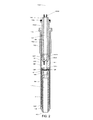
図1は、燃焼エンジン用の圧力測定プラグ100の実施例の断面図を概略的に示す。測定プラグ100は、中空のプラグボディ102、感知モジュール104、相互接続モジュール108、電子回路116およびハウジング110を含む。ハウジング110は、レンチによる測定プラグの装着を可能にするための、六角形の外周(図示せず)を備える。
FIG. 1 schematically shows a cross-sectional view of an embodiment of a
中空のプラグボディ102は、遠位端102Dおよび近位端102Pを含む。中空のプラグボディは、燃焼エンジンのシリンダーヘッドにプラグボディ102を装着するための雄ネジ102Aを備える。中空のプラグボディ102は、プラグボディ軸102Cを有する。プラグボディ軸は、圧力測定プラグ100の長手方向の軸と一致する。ハウジング110のベース部110Aは、中空のプラグボディ102の遠位端102Dに溶接によって取り付けられる。ハウジングはさらに、コネクタ素子(図示せず)を備えるキャップ110Bを含む。ハウジング110は、条件付け電子部品やコネクタ素子のような電子部品116を収容するように構成される。電子回路または電子部品は、次の動作のうちの少なくとも1つを実行するように配置される:圧力センサ、すなわちピエゾ抵抗素子から取得された信号の温度補償、少なくとも1つの電気的感知素子から取得された信号のキャリブレーション、内部故障検出、少なくとも1つの電気的感知素子から条件付けされた信号への変換、すなわち燃焼チャンバ内の圧力を示す信号への電気信号の変換である。
The
感知モジュール104は、中空のプラグボディ102内に配置される。中空のプラグボディ内で感知モジュールが占有する領域は、図1にAで示される。感知モジュール104は、中空のプラグボディの近位端104Pに取り付けられる。感知モジュールは、エンジンの燃焼チャンバ内の圧力を測定するように構成される。感知モジュール104は、第1の細長の環状のボディ部104B、リング形状の感知構造104Aおよび第2の細長の環状のボディ部104Cを含む。第1の細長の環状のボディ部104Bは、一方の端部で中空のプラグボディ102の近位端102Pに溶接により取り付けられ、中空のプラグボディ内を延在して、中空のプラグボディの近位端から一定距離でリング形状の感知構造104Aを位置決めし、それゆえ燃焼チャンバから遠ざけられる。リング形状の感知構造104Aは、第1の細長の環状のボディ部104Bの他方の端部に取り付けられる。
The
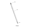
少なくとも1つの電気的な感知素子(図示せず)は、燃焼チャンバから逸されたリング形状の感知構造の表面上に配置される。少なくとも1つの電気的な感知素子は、歪みゲージ(例えば、マイクロフューズド歪みゲージ(MSG)のようなシリコン歪みゲージ)の形態であることができる。歪みゲージは、好ましくはピエゾ抵抗感知素子である。少なくとも1つの電気的な感知素子は、燃焼チャンバ内の圧力の変動によるリング形状の感知構造104Aの使用中の変形を測定するように構成される。感知モジュールの動作原理は、出願人の特許出願EP2138819により詳細に説明されている。第2の細長の環状のボディ部104Cは、第1の細長の環状のボディ部104B内に配置され、リング形状の感知構造104Aに一方の端部で結合される。第2の細長の環状のボディ部104Cは、ロッド状の素子を受け取るための空間を形成する。ロッド状の素子の例は、グローロッド、温度ロッド、およびダミーロッドであるが、これらに限定されない。
At least one electrical sensing element (not shown) is disposed on the surface of the ring-shaped sensing structure that is displaced from the combustion chamber. The at least one electrical sensing element can be in the form of a strain gauge (eg, a silicon strain gauge such as a microfused strain gauge (MSG)). The strain gauge is preferably a piezoresistive sensing element. The at least one electrical sensing element is configured to measure in-use deformation of the ring-shaped
リング形状の支持104Dは、リング形状の感知構造104Aの外周に取り付けられる。プリント配線基板104Eは、リング形状の支持104D上に位置決めされる。リング形状の支持104Dは、リング形状の感知構造104Aから最小の距離でプリント配線基板(PWB)104Eを位置決めするように構成され、その結果、プラグボディ軸の方向のプリント配線基板上に作用する力は、リング形状の感知構造104Aの外周に導かれる。この方法で、圧力測定プラグ内の変動する力による測定信号の歪みが著しく減少される。
The ring-shaped
感知モジュール104はさらに、アライメント素子104Fを含む。アライメント素子104Fは、中空のプラグボディ102内に位置される感知モジュール104の端部を形成する。アライメント素子104Fは、感知モジュール104の上面図を示す図9でより詳細に理解され得る。アライメント素子は、後でより詳細に説明するアライメント構造104F1を含む。アライメント素子104Fは、2つの大きな開口104F2を有するディスク形状の部分を含む。大きな開口104F2のそれぞれは、リング形状の感知構造に取り付けられる電気的な感知素子104A1、ボンディングワイヤ902およびPWB104Eの部品上を延在する。ボンディングワイヤ902は、電気的な感知素子104A1をPWBに電気的に結合する。
The
上述のように、感知構造は、中空のプラグボディ内に、以下の素子の積み重ねである端部を含む:リング形状の感知構造104A、リング形状の支持104D、PWB104Eおよびアライメント素子104Fである。アライメント素子104Fは、リング形状の支持104Dの連結構造104D1により、リング形状の支持104Dに機械的に連結される。連結構造104D1は、アライメント素子104Fのそれぞれの開口内で押しつぶされる。他の連結構造がアライメント素子をリング形状の支持に取り付けてもよいことが明らかであろう。
As described above, the sensing structure includes an end that is a stack of the following elements within a hollow plug body: a ring-shaped
アライメント素子104Fはさらに、中央の開口106と、4つの小さな開口104F3とを含む。4つの開口104F3のそれぞれは、相互接続構造のフレキシブルコンタクトをPWB104Eの接触領域104E1にガイドするように、また、この接触領域上の適所にこのフレキシブルコンタクトを保つように構成される。
The
感知モジュール104は、中空のプラグボディ102内に細長い孔内に一部分として組み立てられる。この方法で、電気的な感知素子およびPWBは、燃焼チャンバから離れて位置決めされて、その結果、プラグボディ内の電子部品にとって厳しい運転条件が少なくなる。測定プラグを組み立てる方法は、
感知モジュールと中空のプラグボディの組み立てを提供し、感知モジュールのPWBが、中空のプラグボディの開口端部から離れて位置されることと、
中空のプラグボディ内で相互接続モジュールを摺動させて、相互接続モジュールと感知モジュールのPWBとの間を電気的に接続することを含む。
The
Providing an assembly of the sensing module and the hollow plug body, wherein the PWB of the sensing module is located away from the open end of the hollow plug body;
Sliding the interconnect module within the hollow plug body to electrically connect between the interconnect module and the sensing module PWB.
相互接続モジュール108は、ハウジング110のキャビティ内の電子部品116を感知モジュール104のPWBへ中空のプラグボディ102を介して電気的に接続するように構成される。相互接続モジュールが中空のプラグボディ内で占有する領域を、図1にBで示す。相互接続モジュール108は、第1の端子108Cが設けられた近位端108Pと、第2の端子108B1が設けられた遠位端108Dとを有する細長の支持構造108Aを含む。第1の端子108Cは、プラグボディ軸102Cに平行のばね軸を有する螺旋状の圧縮ばねの形態のスプリングタイプの端子である。第2の端子108B1は、本実施例では圧入端子である。第2の端子108B1は、圧力測定プラグ100のハウジング110内に配置されたPWBに電気的に結合される。
The
螺旋状の圧力コイルばねは、軸方向にフレキシブルな電気的接続を提供する。本出願におけるフレキシブルな電気的接続が意味するのは、接続により結合された2つの電気部品間の距離は、ひとつの圧力測定プラグ内で、または複数の測定プラグ間で、時間的に変化することができることであり、2つの電気部品の電気的な接続の信頼性が維持される。軸方向のフレキシブルな電気的接続によって、中空のプラグボディの熱膨張係数とは異なる熱膨張係数を有する細長の支持構造用の材料を使用することが可能になる。膨張の差は、フレキシブルな結合により補償される。さらに、軸方向のフレキシブルな結合により、中空のプラグボディ、相互接続モジュール、および感知モジュールの長さの変化を補償することができる。 A spiral pressure coil spring provides an axially flexible electrical connection. The flexible electrical connection in this application means that the distance between two electrical components joined by the connection varies in time within one pressure measuring plug or between several measuring plugs. The reliability of the electrical connection between the two electrical components is maintained. The axial flexible electrical connection allows the use of an elongated support structure material having a coefficient of thermal expansion different from that of the hollow plug body. The difference in expansion is compensated by flexible coupling. Further, the flexible coupling in the axial direction can compensate for changes in the length of the hollow plug body, the interconnect module, and the sensing module.
相互接続モジュール108は、中空のプラグボディの遠位端102Dの開口を通って中空のプラグボディ内の細長い孔内にある。図2は、相互接続モジュールが中空のプラグボディ内の最終的な位置にない断面図を示す。相互接続モジュールの最終的な位置では、細長の支持構造108Pの第1の端部が中空のプラグボディ102の内壁上の突出部102Eに抗するように位置いる。本実施例において、突出部とは、中空のプラグボディ102の内側に沿った環状の縁部である。突出部102Eは、中空のプラグボディ102内において相互接続モジュールの近位端108Pの軸方向の位置を規定し、その結果、相互接続モジュール108の近位端108Pと感知モジュール104のPWB104Eの間の距離を規定する。PWB104Eは、プラグボディ軸と垂直の平面にある複数の接触領域104E1を含む。相互接続構造108を挿入した後、第1の端子108Cの螺旋状のばねは、この複数の接触領域に接触する。突出部102Eを使用は、螺旋状のばね端子が感知モジュール104のPWBに作用する力を制限する。細長の支持構造と中空のプラグボディとの材料の熱膨張係数は異なることがある。突出部の使用は、中空のプラグボディ内において相互接続モジュール108の軸方向の位置を固定することによる感知モジュールのPWBに作用する力に関して、これの影響を減少させる。
The
相互接続構造108はさらに、相互接続モジュール108の遠位端108Dの環状の縁部に弾性のOリングを含む。遠位端108Dは、中空のプラグボディ102の遠位端102Dに位置する。ハウジング110のベース部110Aがプラグボディ102の遠位端102Dに取り付けられた後に、突出部102Eと組み合わされた弾性のOリング108Eは、中空のプラグボディ102内の軸方向に相互接続モジュールを固定する。弾性のOリング108Eによってさらに、細長の支持構造と中空のプラグボディとの材料の熱膨張係数の差による相互接続モジュール108の細長の支持構造108Aの応力量を削減することが可能となる。
The
感知モジュール104および相互接続モジュール108の双方は、ハウジングにより形成されるキャビティから測定プラグの先端までの1つの貫通孔106を形成する中央通路を含む。貫通孔106は、グローロッド、温度感知ロッドおよびダミーロッドのようなロッド形状の素子を受け取るように構成されるが、これらの例に限定されない。グローロッドと温度感知ロッドの両方は、貫通孔106を介して提供される電気的な接続を必要とする。
Both the
感知モジュール104のアライメント素子104Fと、接続モジュール108の細長の支持構造108Aとは、協働するアライメント構造104F1、108A2を含む。これらアライメント構造は、感知構造104に対して相互接続構造108を整合させるように構成されて、相互接続構造108の端子は、感知モジュールのPWB上の対応する接触領域と電気的に接続する。アライメント素子104Fのアライメント構造104F1は、ハウジングの方向に向かう先端を有する2つの矢印形状の構造を含む。アライメント素子104Fのアライメント構造104F1は、細長の支持構造108の近位端108Pで中心の孔内へ突出するように構成される。中心孔の表面は、相互接続モジュール108のアライメント構造108A2Aを形成する矢印形状の輪郭を有する。アライメント構造108A2の輪郭は、感知モジュールの方向に向かう先端を含む。図1は、感知モジュールおよび相互接続モジュールの整合された位置を示す。図2は、相互接続モジュールのアライメント構造108A2Aの先端が感知モジュールのアライメント構造104F1の先端に接触している状況を示す。この状況は、相互接続モジュールが中空のプラグボディに目に見えない状態で挿入されるときに生じ得る。アライメント構造は、感知構造の方向に移動する間に相互接続構造をプラグボディ軸102Cの周りで回転させる。感知モジュールおよび相互接続モジュールが相互に正確な配向を有しているとき、相互接続モジュールの近位端が中空のプラグボディ102の突出部102Eにぶつかるまで、相互接続モジュールは、プラグボディ軸の周りで回転されることなく、軸方向において感知モジュールまで移動され得る。端子108Cの螺旋状のばねは軸方向に圧縮され、感知モジュール104のPWB上の接触領域に接触する。それゆえ、感知モジュールと電気的に接触するために相互接続モジュールの端子が測定プラグの軸方向に移動された後に、感知モジュールおよび相互接続モジュールのアライメント構造は、これらのモジュールの配向を整合させるために最初に相互接続モジュールを回転させるように構成される。アライメント素子104Fの開口104F3は、螺旋状のばねの形態の端子をPWB上の対応する接触領域へ導く。開口104F3はさらに、螺旋状のばねが圧縮された後に軸方向において曲がらないことを保証する。軸方向において螺旋状のばねを曲げると、PWBの接触領域との接触が失われることになり得る。
The
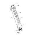
図3から図8は、相互接続モジュール108をより詳細に示す。図3は、相互接続モジュールの側面図を示す。相互接続モジュール108は、導電性のストリップ状の素子108Bを含む。ストリップ状の素子108Bは、細長の支持構造108Aの遠位端108Dから近位端108Pまで延在する。遠位端108Dでは、ストリップ状の素子108Bは圧入端子を含む。近位端108Pでは、ストリップ状の素子108Bは、端子の一部を形成する針(ニードル)状の端部108B2を含む。針状の端部108B2は、螺旋状のばねの開口に押しこめられて、ここに固定される。図3は、相互接続モジュール108の側面図を示す。細長の支持構造108Aは、プラスチック材料から作られることができるものであり、第1の部分108A1および第2の部分108A2を含む。Oリング108Eは、第1の部分108A1に取り付けられる。図6は相互接続モジュールの上面図を示し、図7は相互接続モジュールの底面図を示す。相互接続モジュールは回転対称の構造を有することが理解されよう。端子は相互接続モジュールの縦軸の周りに回転対称に分布される。本実施例におけるこの分布は、相互接続モジュールが、ハウジング内の電子部品に感知モジュールを電気的に接続するための2つの可能性を有するものである。図6および図7はさらに、ハウジングから測定プラグの先端までの通路を形成する中心の孔106を示す。図7はさらに、アライメント構造108A2Aの2つの先端と、感知モジュールのアライメント構造を受け取るための2つの窪み108A2Bとを示す。図7はさらに、針状の端部108B2の先端が螺旋状のばね素子108Cの開口に挿入されることを示す。
3-8 show the
図8は、図6および図7における線VIII‐VIIIに沿った相互接続モジュールの断面図である。1つの導電性のストリップ状の素子108Bのみが示されていることに留意すべきである。この図が示すのは、細長の支持構造108Aが導電性のストリップ状の素子108Bを受け取るように構成される長手方向の窪み602を含むことである。窪み602は、プラグボディ軸と平行に延在する。長手方向の窪み602は、細長の支持構造108Aの遠位端108Dにある第1の部分108A1の貫通孔604内の1つの端部で終わる。長手方向の窪み602は、第2の部分108A2の貫通孔の反対側の端部で終わる。ストリップ状の素子108Bを細長の支持構造の長手方向に固定するために、細長の窪み602とストリップ状の素子108Bの両方が、細長の支持構造108の端部方向に向かって狭くなる構造を含む。
FIG. 8 is a cross-sectional view of the interconnect module along line VIII-VIII in FIGS. 6 and 7. It should be noted that only one conductive strip-
第1の部分108A1および第2の部分108A2は、スナップフィットを用いて結合される。参照番号108A1Aは、細長の支持構造108Aの第1の部分108A1のスナップフィット構造を示し、参照番号108A2Aは、細長の支持構造108Aの第2の部分108A2のスナップフィット構造を示す。
The first portion 108A1 and the second portion 108A2 are joined using a snap fit. Reference numeral 108A1A indicates the snap-fit structure of the first portion 108A1 of the
相互接続モジュール108は、以下の方法で組み立てられる。まず、4つのストリップ状の素子108Bが第1の部分の窪みに位置決めされる。これは、圧入端子108B1を有するストリップ状の端子の端部を、開口を通して、細長の支持構造の遠位端を形成する第1の部分の領域に挿入することによって成される。続いて、ストリップ状の素子を窪み602内に位置決めする。この後、第2の部分108A2がストリップ状の素子の針状の端部上に移動され、第1の部分108A1にスナップフィットされる。それから、螺旋状のばね素子108Cが導電性のストリップ状の素子の針状の端部に取り付けられる。最後に、弾性のOリング108Eが細長の支持構造108Aの遠位端に取り付けられる。
The
相互接続モジュール108を組み立てる別の方法では、螺旋状のばねがストリップ状の素子の針状の端部の周りに位置決めされる。このばねは、ばねをクランピングすること、溶接すること、または変形させることにより、針状の端部に取り付けることができる。その後、4つのストリップ状の素子108Bが第1の部分の窪み内に位置決めされる。これは、圧入端子108B1を有するストリップ状の素子の端部を、開口を介して、細長の支持構造の遠位端を形成する第1の部分の領域に挿入することによって成される。続いて、ストリップ状の素子が窪み602内に位置決めされる。この後、第2の部分108A2が、ストリップ状の素子の針状の端部に位置する螺旋状のばねに対して移動され、または押し付けられ、第1の部分108A1にスナップフィットされる。
In another method of assembling the
好ましくは、第2の部分108A2の開口は、螺旋状のばねの断面よりもわずかに小さい断面を有する。この方法で、螺旋状のばねは、挿入後に第2の部分108A2の開口に固定される。 Preferably, the opening of the second portion 108A2 has a cross section that is slightly smaller than the cross section of the helical spring. In this way, the helical spring is secured to the opening of the second portion 108A2 after insertion.
細長の支持構造およびストリップ状の素子の組み立てが、オーバーモールド工程によって得ることができることに留意されたい。 Note that the elongated support structure and the assembly of strip-like elements can be obtained by an overmolding process.
図10は、測定プラグで使用するための相互接続の第2の実施例の斜視図を示す。この実施例は、中心の孔を含まない点で、前述の実施例とは異なる。これによって、この実施例が、空間内の圧力のみを測定する測定プラグに適したものとなる。別の相違点は、相互接続モジュールのアライメント構造108A2A’が外側の面に位置することである。アライメント構造104F1’を有する対応するアライメント構造104Fもまた図10に示される。弾性のOリングはこの図では示されていない。
FIG. 10 shows a perspective view of a second embodiment of an interconnect for use with a measurement plug. This embodiment differs from the previous embodiment in that it does not include a central hole. This makes this embodiment suitable for a measuring plug that measures only the pressure in the space. Another difference is that the interconnect module alignment structure 108A2A 'is located on the outer surface. A
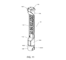
図11は、相互接続モジュールの第3の実施例の斜視図を示す。この実施例では、相互接続モジュールは電子回路を含む。電子回路は、感知モジュールの電子的な感知素子によって発生される電子信号を条件付けるように配置される。相互接続モジュールの遠位端108Dに、接触領域1108が設けられる。ハウジング内のPWBに取り付けられた螺旋状の接触ばねは、ハウジング内の電子部品と相互接続モジュール上の回路との間の電気的な接続のために使用されることができる。この実施例では、近位端108Pでの相互接続モジュール108のアライメント構造108A2A’は、細長の支持構造108Aの外側の面にある。
FIG. 11 shows a perspective view of a third embodiment of an interconnection module. In this embodiment, the interconnect module includes electronic circuitry. The electronic circuit is arranged to condition an electronic signal generated by the electronic sensing element of the sensing module. A
上述の実施例において、螺旋状のばね素子は、相互接続モジュールと感知モジュールの間の電気的な接続に使用される。他のスプリングタイプの端子が、例えば、板ばね素子との接続のような接続を行うのに使用されることができる。軸方向のフレキシブルな結合は、フレキシブルな導電性のOリングによって、または、相互接続モジュールの端子に取り付けられる先端部分によって提供されてもよい。フレキシブルな導電性材料は、例えば、導電性エラストマーである。相互接続モジュールと感知モジュールの間を電気的に接続するために圧入端子を使用することも可能であろう。しかしながら、圧入端子が使用されるならば、相互接続モジュールのもう一方の側の接続は、プラグボディの軸方向でフレキシブルな結合を持つべきである。 In the embodiment described above, a helical spring element is used for the electrical connection between the interconnection module and the sensing module. Other spring type terminals can be used to make a connection, for example, a connection with a leaf spring element. Axial flexible coupling may be provided by a flexible conductive O-ring or by a tip portion attached to the terminals of the interconnect module. The flexible conductive material is, for example, a conductive elastomer. It would also be possible to use press-fit terminals to make an electrical connection between the interconnect module and the sensing module. However, if press-fit terminals are used, the connection on the other side of the interconnect module should have a flexible connection in the axial direction of the plug body.
ここでの説明は、電気的感知素子を信号条件付け電子回路から比較的長い距離で隔離するための相互接続システムの設計である。この方法で、電子回路は熱的過負荷から保護される。相互接続システムは、自動車のエンジンシリンダーの温度および振動に耐え、大量の組み立ておよび共通プロセスに適している。相互接続構造108は、自動車の温度および振動の要求を満足する。この設計は、異なる長さの様々なエンジンヘッドのレイアウト、およびセンサがプラグボディの一方の端部に位置され、条件付け電子回路がプラグボディの他方の端部に位置される他の測定プラグセンサに適用可能である。
The description here is the design of an interconnect system for isolating the electrical sensing element at a relatively long distance from the signal conditioning electronics. In this way, the electronic circuit is protected from thermal overload. The interconnect system can withstand the temperature and vibration of automobile engine cylinders and is suitable for high volume assembly and common processes. The
相互接続モジュールの遠位端にある圧入端子により、大量生産のための容易な組立が保証される。相互接続モジュールの近位端は、支持リングに取り付けられるPWBの接触領域に接触する螺旋状のばね素子を有する。相互接続モジュールが、感知モジュールの端部に一体化されたアライメント特徴と整合するので、大量生産の際に簡単な組み立てのため目に見えない挿入が可能な方法で、相互接続モジュールは設計される。相互接続モジュールにより、高温抵抗によるセラミックの組み込みが可能となる。 A press-fit terminal at the distal end of the interconnect module ensures easy assembly for mass production. The proximal end of the interconnect module has a helical spring element that contacts the contact area of the PWB attached to the support ring. The interconnect module is designed in such a way that it can be inserted invisible for easy assembly during mass production because the interconnect module aligns with an alignment feature integrated at the end of the sensing module . The interconnect module allows for ceramic incorporation with high temperature resistance.
いくつかの実施例の点から本発明が説明されたが、本発明の代替物、修正物、置換物および等価物が、明細書を読み、図面を検討することによって、当業者に明らかとなろうことが期待される。本発明は説明された実施例に限定されるものではない。本発明の思想から逸脱することなく、変形形態が成されることができる。
Although the invention has been described in terms of several embodiments, alternatives, modifications, substitutions and equivalents of the invention will become apparent to those skilled in the art upon reading the specification and reviewing the drawings. Expected to be deaf. The invention is not limited to the described embodiments. Variations can be made without departing from the spirit of the invention.
Claims (15)
前記プラグボディ(102)の前記遠位端(102D)に取り付けられるハウジング(110)と、
前記ハウジング(100)内に取り付けられる電子部品(116)と、
前記中空のプラグボディ内に配された感知モジュール(104)であって、当該感知モジュールは、少なくとも1つの電気的な感知素子と、当該少なくとも1つの電気的な感知素子に電気的に結合されたPWBとを含み、前記感知モジュールが前記中空のプラグボディ(102)の前記近位端(102P)に取り付けられる前記感知モジュールとを含む測定プラグ(100)であって、
前記測定プラグがさらに、前記中空のプラグボディ(102)を介して前記電子部品(116)を前記感知モジュール(104)に電気的に接続するように構成された相互接続モジュール(108)を含み、
前記相互接続モジュール(108)が、第1の端子(108C)が設けられた第1の端部(108P)と、第2の端子(108B1)が設けられた第2の端部(108D)とを有する細長の支持構造(108A)を含み、前記第1の端子(108C)が軸方向にフレキシブルな電気的結合を提供する、測定プラグ。 A hollow plug body (102) including a proximal end (102P), a distal end (102D) and a plug body axis (102C);
A housing (110) attached to the distal end (102D) of the plug body (102);
An electronic component (116) mounted in the housing (100);
A sensing module (104) disposed within the hollow plug body, wherein the sensing module is electrically coupled to at least one electrical sensing element and the at least one electrical sensing element. A measurement plug (100) comprising: a PWB, wherein the sensing module includes the sensing module attached to the proximal end (102P) of the hollow plug body (102),
The measurement plug further includes an interconnect module (108) configured to electrically connect the electronic component (116) to the sensing module (104) via the hollow plug body (102);
The interconnect module (108) includes a first end (108P) provided with a first terminal (108C) and a second end (108D) provided with a second terminal (108B1). A measuring plug comprising an elongated support structure (108A) having a first terminal (108C) providing an axially flexible electrical coupling.
15. A measuring plug according to claim 14, wherein the electrical element is a glow rod and the sensing module (104) is configured to measure pressure in a combustion chamber.
Applications Claiming Priority (2)
| Application Number | Priority Date | Filing Date | Title |
|---|---|---|---|
| EP13169547.0A EP2808665B1 (en) | 2013-05-28 | 2013-05-28 | A measuring plug |
| EP13169547.0 | 2013-05-28 |
Publications (3)
| Publication Number | Publication Date |
|---|---|
| JP2014232105A true JP2014232105A (en) | 2014-12-11 |
| JP2014232105A5 JP2014232105A5 (en) | 2017-06-22 |
| JP6159683B2 JP6159683B2 (en) | 2017-07-05 |
Family
ID=48470863
Family Applications (1)
| Application Number | Title | Priority Date | Filing Date |
|---|---|---|---|
| JP2014107808A Expired - Fee Related JP6159683B2 (en) | 2013-05-28 | 2014-05-26 | Measuring plug |
Country Status (6)
| Country | Link |
|---|---|
| US (1) | US9500125B2 (en) |
| EP (1) | EP2808665B1 (en) |
| JP (1) | JP6159683B2 (en) |
| KR (1) | KR102098973B1 (en) |
| CN (1) | CN104215390B (en) |
| IN (1) | IN2014CH02588A (en) |
Families Citing this family (10)
| Publication number | Priority date | Publication date | Assignee | Title |
|---|---|---|---|---|
| FR3024542B1 (en) * | 2014-07-31 | 2016-09-02 | Continental Automotive France | SUPPORT OF AN ELECTRONIC MODULE OF A PRESSURE MEASURING SENSOR |
| WO2016196596A1 (en) | 2015-06-01 | 2016-12-08 | Prime Datum Development Company, Llc | Line replaceable unit (lru) sensor systems for motors and other machines |
| GB201509927D0 (en) * | 2015-06-08 | 2015-07-22 | Aes Eng Ltd | Electrical grounding - labyrinth bearing protector |
| DK3124938T3 (en) * | 2015-07-31 | 2019-05-13 | Kistler Holding Ag | PRESSURE SENSOR |
| DE102015012740A1 (en) * | 2015-10-01 | 2017-04-06 | Wabco Gmbh | Vehicle control unit |
| JP6374550B1 (en) * | 2017-02-27 | 2018-08-15 | 日立オートモティブシステムズ株式会社 | Pressure sensor |
| US10545064B2 (en) * | 2017-05-04 | 2020-01-28 | Sensata Technologies, Inc. | Integrated pressure and temperature sensor |
| US11153985B2 (en) * | 2017-06-29 | 2021-10-19 | Rosemount Inc. | Modular hybrid circuit packaging |
| CN209326840U (en) | 2018-12-27 | 2019-08-30 | 热敏碟公司 | Pressure sensor and pressure transmitter |
| US12200888B2 (en) | 2022-02-01 | 2025-01-14 | Rosemount Inc. | Customization of process variable transmitter with hermetically sealed electronics |
Citations (8)
| Publication number | Priority date | Publication date | Assignee | Title |
|---|---|---|---|---|
| JP3681494B2 (en) * | 1997-02-03 | 2005-08-10 | カルソニックカンセイ株式会社 | Pressure sensor |
| US6948372B2 (en) * | 2004-01-08 | 2005-09-27 | Delphi Technologies, Inc. | Method of connection to a spark plug pressure sensor |
| JP3912400B2 (en) * | 2004-03-30 | 2007-05-09 | 株式会社デンソー | Pressure sensor |
| JP5726408B2 (en) * | 2008-06-25 | 2015-06-03 | センサータ テクノロジーズ インコーポレーテッド | Piezoresistive pressure measuring plug for internal combustion engine |
| JP5748554B2 (en) * | 2010-05-27 | 2015-07-15 | センサータ テクノロジーズ インコーポレーテッド | Pressure sensor |
| JP5783566B2 (en) * | 2010-10-20 | 2015-09-24 | センサータ テクノロジーズ インコーポレーテッド | Pressure measuring plug for combustion engines |
| JP6009950B2 (en) * | 2012-01-27 | 2016-10-19 | センサータ テクノロジーズ インコーポレーテッド | Small Form Factor Microfused Silicon Strain Gauge (MSG) Pressure Sensor Packaging |
| JP6124823B2 (en) * | 2013-03-20 | 2017-05-10 | センサータ テクノロジーズ インコーポレーテッド | Measuring plug and method for assembling a measuring plug |
Family Cites Families (13)
| Publication number | Priority date | Publication date | Assignee | Title |
|---|---|---|---|---|
| US5880372A (en) * | 1997-01-10 | 1999-03-09 | Integrated Sensor Solutions | Media compatible pressure sensor device utilizing self-aligned components which fit together without the need for adhesives |
| US6668632B2 (en) * | 2001-03-05 | 2003-12-30 | Delphi Technologies, Inc. | Spark apparatus with pressure signal response amplification |
| US6742395B1 (en) * | 2002-12-20 | 2004-06-01 | Texas Instruments Incorporated | Hermetic pressure transducer |
| JP3942176B2 (en) * | 2003-03-17 | 2007-07-11 | 日本特殊陶業株式会社 | Glow plug with combustion pressure detection function and manufacturing method thereof |
| DE10333438A1 (en) * | 2003-07-23 | 2005-02-17 | Robert Bosch Gmbh | Combustion chamber pressure sensor with metal diaphragm with piezoresistive metal thin film |
| DE10343521A1 (en) * | 2003-09-19 | 2005-04-21 | Beru Ag | Pressure measuring glow plug for a diesel engine |
| ATE544034T1 (en) * | 2004-09-15 | 2012-02-15 | Beru Ag | PRESSURE MEASUREMENT GLOW PLUG FOR A DIESEL ENGINE |
| JP2006307834A (en) * | 2005-03-31 | 2006-11-09 | Ngk Spark Plug Co Ltd | Combustion pressure sensor and glow plug provided with the same |
| FR2884298B1 (en) * | 2005-04-12 | 2007-08-10 | Siemens Vdo Automotive Sas | PRE-HEATING CUP WITH INTEGRATED PRESSURE SENSOR |
| CH699078A1 (en) * | 2008-07-02 | 2010-01-15 | Kistler Holding Ag | Spark plug in basic structure with pressure sensor. |
| US8217309B2 (en) * | 2008-12-15 | 2012-07-10 | Federal-Mogul Italy Srl. | Glow plug with pressure sensing canister |
| CN101793578A (en) * | 2010-02-10 | 2010-08-04 | 中国人民解放军63908部队 | Chock plug capable of protecting pressure sensor from being ablated |
| CN102162406B (en) * | 2011-03-31 | 2012-07-25 | 重庆长安汽车股份有限公司 | Mounting structure of motor cylinder pressure sensor |
-
2013
- 2013-05-28 EP EP13169547.0A patent/EP2808665B1/en not_active Not-in-force
-
2014
- 2014-05-23 US US14/286,617 patent/US9500125B2/en not_active Expired - Fee Related
- 2014-05-26 JP JP2014107808A patent/JP6159683B2/en not_active Expired - Fee Related
- 2014-05-26 IN IN2588CH2014 patent/IN2014CH02588A/en unknown
- 2014-05-27 KR KR1020140063688A patent/KR102098973B1/en not_active Expired - Fee Related
- 2014-05-28 CN CN201410392535.8A patent/CN104215390B/en not_active Expired - Fee Related
Patent Citations (8)
| Publication number | Priority date | Publication date | Assignee | Title |
|---|---|---|---|---|
| JP3681494B2 (en) * | 1997-02-03 | 2005-08-10 | カルソニックカンセイ株式会社 | Pressure sensor |
| US6948372B2 (en) * | 2004-01-08 | 2005-09-27 | Delphi Technologies, Inc. | Method of connection to a spark plug pressure sensor |
| JP3912400B2 (en) * | 2004-03-30 | 2007-05-09 | 株式会社デンソー | Pressure sensor |
| JP5726408B2 (en) * | 2008-06-25 | 2015-06-03 | センサータ テクノロジーズ インコーポレーテッド | Piezoresistive pressure measuring plug for internal combustion engine |
| JP5748554B2 (en) * | 2010-05-27 | 2015-07-15 | センサータ テクノロジーズ インコーポレーテッド | Pressure sensor |
| JP5783566B2 (en) * | 2010-10-20 | 2015-09-24 | センサータ テクノロジーズ インコーポレーテッド | Pressure measuring plug for combustion engines |
| JP6009950B2 (en) * | 2012-01-27 | 2016-10-19 | センサータ テクノロジーズ インコーポレーテッド | Small Form Factor Microfused Silicon Strain Gauge (MSG) Pressure Sensor Packaging |
| JP6124823B2 (en) * | 2013-03-20 | 2017-05-10 | センサータ テクノロジーズ インコーポレーテッド | Measuring plug and method for assembling a measuring plug |
Also Published As
| Publication number | Publication date |
|---|---|
| US9500125B2 (en) | 2016-11-22 |
| CN104215390B (en) | 2019-02-19 |
| US20140352415A1 (en) | 2014-12-04 |
| EP2808665A1 (en) | 2014-12-03 |
| EP2808665B1 (en) | 2019-02-20 |
| KR102098973B1 (en) | 2020-04-09 |
| JP6159683B2 (en) | 2017-07-05 |
| CN104215390A (en) | 2014-12-17 |
| KR20140139976A (en) | 2014-12-08 |
| IN2014CH02588A (en) | 2015-07-03 |
Similar Documents
| Publication | Publication Date | Title |
|---|---|---|
| JP6159683B2 (en) | Measuring plug | |
| US6973820B2 (en) | Combustion pressure sensor designed to ensure stability of output characteristic and sensitivity | |
| CN103852109B (en) | The method of integrated temperature sensing element | |
| JP5975793B2 (en) | Combustion pressure sensor | |
| US7114396B2 (en) | Pressure sensor | |
| JP6124823B2 (en) | Measuring plug and method for assembling a measuring plug | |
| EP1707935A1 (en) | Combustion pressure sensor and glow plug including the same | |
| HK1204031A1 (en) | Combustion pressure detection device, and internal combustion engine equipped with combustion pressure detection device | |
| JP5978073B2 (en) | Combustion pressure sensor | |
| JP5067138B2 (en) | Pressure sensor | |
| JP2013174553A (en) | Pressure detection device, and internal combustion engine equipped with pressure detection device | |
| JP5893920B2 (en) | Detection system and detection device | |
| JP2012181127A (en) | Pressure sensor | |
| JP2005249512A (en) | Pressure detection device | |
| JP2013140044A (en) | Pressure detector and internal combustion engine having pressure detector | |
| JP2005351789A (en) | Manufacturing method of pressure detecting device | |
| CN108369150A (en) | A method for manufacturing a sensor for sensing at least one property of a fluid medium in a measurement chamber | |
| JP6357454B2 (en) | Pressure detection device | |
| JP6314766B2 (en) | Physical quantity sensor and manufacturing method thereof | |
| JP2017181191A (en) | Pressure detection device and piezoelectric element | |
| JP2023049395A (en) | Pressure sensing device | |
| JP2013204938A (en) | Glow plug | |
| JP2005249513A (en) | Pressure detection device | |
| JP2005265796A (en) | Pressure detection device |
Legal Events
| Date | Code | Title | Description |
|---|---|---|---|
| A521 | Request for written amendment filed |
Free format text: JAPANESE INTERMEDIATE CODE: A523 Effective date: 20170515 |
|
| A621 | Written request for application examination |
Free format text: JAPANESE INTERMEDIATE CODE: A621 Effective date: 20170515 |
|
| A871 | Explanation of circumstances concerning accelerated examination |
Free format text: JAPANESE INTERMEDIATE CODE: A871 Effective date: 20170515 |
|
| A975 | Report on accelerated examination |
Free format text: JAPANESE INTERMEDIATE CODE: A971005 Effective date: 20170516 |
|
| TRDD | Decision of grant or rejection written | ||
| A01 | Written decision to grant a patent or to grant a registration (utility model) |
Free format text: JAPANESE INTERMEDIATE CODE: A01 Effective date: 20170530 |
|
| A61 | First payment of annual fees (during grant procedure) |
Free format text: JAPANESE INTERMEDIATE CODE: A61 Effective date: 20170612 |
|
| R150 | Certificate of patent or registration of utility model |
Ref document number: 6159683 Country of ref document: JP Free format text: JAPANESE INTERMEDIATE CODE: R150 |
|
| R250 | Receipt of annual fees |
Free format text: JAPANESE INTERMEDIATE CODE: R250 |
|
| R250 | Receipt of annual fees |
Free format text: JAPANESE INTERMEDIATE CODE: R250 |
|
| LAPS | Cancellation because of no payment of annual fees |