JP2014237191A - Discharge processing method - Google Patents
Discharge processing method Download PDFInfo
- Publication number
- JP2014237191A JP2014237191A JP2013120870A JP2013120870A JP2014237191A JP 2014237191 A JP2014237191 A JP 2014237191A JP 2013120870 A JP2013120870 A JP 2013120870A JP 2013120870 A JP2013120870 A JP 2013120870A JP 2014237191 A JP2014237191 A JP 2014237191A
- Authority
- JP
- Japan
- Prior art keywords
- electric discharge
- finish
- discharge machining
- workpiece
- machining method
- Prior art date
- Legal status (The legal status is an assumption and is not a legal conclusion. Google has not performed a legal analysis and makes no representation as to the accuracy of the status listed.)
- Granted
Links
- 238000003672 processing method Methods 0.000 title claims abstract description 5
- 238000000034 method Methods 0.000 claims abstract description 51
- 238000003754 machining Methods 0.000 claims description 82
- 239000000523 sample Substances 0.000 claims description 13
- 238000009760 electrical discharge machining Methods 0.000 claims description 6
- 239000002699 waste material Substances 0.000 abstract description 18
- 238000010586 diagram Methods 0.000 description 12
- 230000003746 surface roughness Effects 0.000 description 9
- 238000007730 finishing process Methods 0.000 description 2
- 230000001154 acute effect Effects 0.000 description 1
- 239000004020 conductor Substances 0.000 description 1
- 238000005498 polishing Methods 0.000 description 1
- 238000007788 roughening Methods 0.000 description 1
Images






Landscapes
- Electrical Discharge Machining, Electrochemical Machining, And Combined Machining (AREA)
Abstract
Description
本発明は放電加工方法に関する。 The present invention relates to an electric discharge machining method.
ワイヤ電極と被加工物との間にアークを発生させて、アークによる熱を利用して被加工物を加工する放電加工方法がある。 There is an electric discharge machining method in which an arc is generated between a wire electrode and a workpiece, and the workpiece is machined using heat generated by the arc.
例えば、特許文献1では、ワイヤ電極をV字状に繰り返し移動させて、溝を被加工体の表面に形成する放電加工方法が開示されている。このような放電加工方法によれば、放電加工中に発生する加工屑のサイズを縮小させることができる。加工屑が小さくなるので、ワイヤ電極と衝突しても、ワイヤ電極が断線しにくい。
For example,
ところで、すでに仕上げを行った仕上部を有する被加工体を、ワイヤ電極により放電加工することがある。かかる放電加工では、加工屑が仕上部に付着し、仕上部の寸法精度や面粗さを悪化させることがあった。 By the way, a workpiece having a finished surface that has already been finished may be subjected to electric discharge machining with a wire electrode. In such electric discharge machining, machining scraps may adhere to the finish, which may deteriorate the dimensional accuracy and surface roughness of the finish.
例えば、図14に示す被加工体900を加工する場合がある。被加工体900は、仕上部としての接触球921と、接触球921に連続的につながった接続部902と、を有する棒状体である。図14に示すように、接続部902をワイヤ電極990により放電加工すると、軸部922が形成する。このとき、加工屑が接続部902から飛んで、接触球921に付着する。これにより、仕上部としての接触球921の寸法精度や面粗さが悪化することがある。
For example, the
本発明はこのような状況を鑑みてなされたものであり、加工屑の仕上部への付着を抑制する放電加工方法を提供することを目的とする。 This invention is made | formed in view of such a condition, and it aims at providing the electric discharge machining method which suppresses adhesion to the finishing surface of a process waste.
本発明にかかる放電加工方法は、
ワイヤ電極を備える放電加工機を用いて、
先端部と、前記先端部に連続的につながった接続部と、を有する棒状の被加工体を加工して、仕上部と、前記仕上部に連続的につながった軸部と、を有する加工体を得る加工方法であって、
前記接続部を、前記先端部から離れるにつれて断面積が連続的に増加する形状に加工する工程と、
前記先端部を仕上げして、前記仕上部を形成する工程と、
前記接続部を放電加工して、前記軸部を形成する工程と、を含む。
The electric discharge machining method according to the present invention is:
Using an electric discharge machine with wire electrodes,
A workpiece having a finish and a shaft continuously connected to the finish by processing a rod-like workpiece having a tip and a connection continuously connected to the tip. A processing method for obtaining
Processing the connection part into a shape in which a cross-sectional area continuously increases as the distance from the tip part increases;
Finishing the tip and forming the finish;
Forming the shaft portion by electrical discharge machining of the connecting portion.
このような構成によれば、加工屑の仕上部への付着を抑制することができる。 According to such a configuration, it is possible to suppress adhesion of the processing waste to the finish.
他方、本発明にかかる放電加工方法は、
ワイヤ電極を備える放電加工機を用いて、
すでに仕上げされた仕上部と、前記仕上部に連続的につながった接続部と、を有する棒状の被加工体を放電加工して、前記仕上部と、前記仕上部に連続的につながった軸部と、を有する加工体を得る放電加工方法であって、
前記ワイヤ電極を前記被加工体の軸線に対して傾斜させるように張りつつ前記接続部に接近させて、前記接続部を放電加工して、前記軸部を形成する。
On the other hand, the electric discharge machining method according to the present invention is:
Using an electric discharge machine with wire electrodes,
A rod-like workpiece having an already finished finish and a connecting portion continuously connected to the finish is subjected to electric discharge machining, and the finish and a shaft portion continuously connected to the finish. And an electric discharge machining method for obtaining a workpiece having:
The wire electrode is moved so as to be inclined with respect to the axis of the workpiece, approached to the connecting portion, and the connecting portion is subjected to electric discharge machining to form the shaft portion.
他方、本発明にかかる放電加工方法は、
ワイヤ電極を備える放電加工機を用いて、
すでに仕上げされた仕上部と、前記仕上部に連続的につながった接続部とを有する棒状の被加工体を放電加工して、前記仕上部と、前記仕上部に連続的につながった軸部と、を有する加工体を得る放電加工方法であって、
遮蔽板を前記接続部と対向するように配置するとともに、
前記ワイヤ電極を前記遮蔽板と前記接続部との間に配置して、前記接続部を放電加工して、前記軸部を形成する。
On the other hand, the electric discharge machining method according to the present invention is:
Using an electric discharge machine with wire electrodes,
An electrical discharge machining is performed on a rod-like workpiece having a finished finish and a connection portion continuously connected to the finish, and the finish and a shaft portion continuously connected to the finish. An electric discharge machining method for obtaining a workpiece having
While arranging the shielding plate to face the connection portion,
The wire electrode is disposed between the shielding plate and the connecting portion, and the connecting portion is subjected to electric discharge machining to form the shaft portion.
他方、本発明にかかるプローブは、上記した放電加工方法により得られる。 On the other hand, the probe according to the present invention is obtained by the electric discharge machining method described above.
本発明は、加工屑の仕上部への付着を抑制する放電加工方法を提供することができる。 The present invention can provide an electric discharge machining method that suppresses adhesion of machining scraps to the finish.
(第1実施形態)
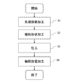
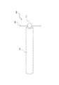
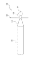
図1を参照しつつ、図2〜9を用いて第1実施形態にかかる放電加工方法について説明する。ここでは、被加工体を加工して、加工体の一例としてプローブを得る場合について説明する。図1は第1実施形態にかかる放電加工方法のフローチャートを示す。図2は被加工体の側面図である。図3〜7、9は、第1実施形態にかかる放電加工方法の模式図を示す。図8は、第1実施形態にかかる放電加工方法により得られたプローブの側面図である。
(First embodiment)
The electric discharge machining method according to the first embodiment will be described with reference to FIGS. Here, a case where a workpiece is processed to obtain a probe as an example of the processed body will be described. FIG. 1 shows a flowchart of an electric discharge machining method according to the first embodiment. FIG. 2 is a side view of the workpiece. 3 to 7 and 9 are schematic views of the electric discharge machining method according to the first embodiment. FIG. 8 is a side view of the probe obtained by the electric discharge machining method according to the first embodiment.
まず、図2に示すように、被加工体100を準備する。被加工体100は、導電性を有する材料からなる棒状体である。被加工体100は、一端部である先端部101と、先端部101に連続的につながった接続部102とを含む。
First, as shown in FIG. 2, a
次いで、図3に示すように、先端部101を略球状に粗加工し、粗形状部111を形成する(先端部粗加工ステップS1)。この粗加工は、例えば、ワイヤ電極190を備える放電加工機(図示略)を用いて行うことができる。被加工体100の他端部を放電加工機の把持部(図示略)に把持させて、ワイヤ電極190を先端部101(図2参照)に接近させて、放電加工して、略球状の粗形状部111に加工することができる。
Next, as shown in FIG. 3, the
次いで、図4に示すように、接続部102の少なくとも一部を傾斜部112に加工する(傾斜形状加工ステップS2)。傾斜部112は、先端部101から離れるにつれて断面積が連続的に増加する形状を有する。このような形状としては、例えば、テーパ形状がある。
Next, as shown in FIG. 4, at least a part of the connecting
次いで、図5に示すように、粗形状部111を仕上げて、仕上部121を形成する(仕上ステップS3)。このような仕上げは、例えば、研磨剤(図示略)を粗形状部111に塗って、電圧をワイヤ電極に印加しないままワイヤ電極を粗形状部111に当接して研磨して行うことができる。また、円筒状の電極を備える放電加工機を用いて行うこともできる。上記したように、傾斜部112は先端部101から離れるにつれて断面積が連続的に増加する形状を有している。したがって、傾斜部112は粗形状部111を仕上げる際に加わる力に耐えられるよう必要な機械的強度を備える。
Next, as shown in FIG. 5, the
最後に、図6及び7に示すように、傾斜部112を軸部122に加工する(軸部放電加工ステップS4)。加工は、図の右側から左側に向けて(仕上部121に近い側から接続部102に向かって)行う。ここで、図7に示すように、加工屑が傾斜部112から発生して、軸部122に付着するものの、仕上部121まで到達し難い。また、傾斜部112から発生する加工屑の量は、棒状の接続部102(図2及び図3参照)をそのまま軸部122に放電加工して発生する加工屑の量と比較して、少ない。さらに、傾斜部112の径の小さい方から大きい方(断面積の小さい方から大きい方)に向かって加工することになるため、仕上部121の近い方では加工屑の発生量が少なく、加工屑が多く発生するときには仕上部121から十分に離れた状態にある。これらにより、加工屑の仕上部121への付着を抑制することができる。
Finally, as shown in FIGS. 6 and 7, the
上記した全てのステップを経ると、図8に示すように、加工体としてのプローブ130を得ることができる。プローブ130は、仕上部121と、仕上部121に連続的につながった軸部122を有する。プローブ130は、例えば、三次元測定機のプローブとして用いられる。加工屑の仕上部121への付着を抑制できるので、仕上部121は寸法精度や面粗さを良好に維持しており、プローブの接触球として良好に機能することができる。
After all the steps described above, a
以上より、本実施形態によれば、加工屑の仕上部121への付着を抑制でき、寸法精度や面粗さを良好に維持した仕上部121を有するプローブを得ることができる。また、本実施形態によれば、新たな放電加工機を必要とすることなく、既存の放電加工機で実施できる。
As described above, according to the present embodiment, it is possible to obtain a probe having the finishing
なお、上記した第1実施形態では、接続部102をテーパ形状に加工したが、先端部101から離れるにつれて断面積を連続的に増加する形状に加工すればよい。このような形状としては、例えば、図9(a)に示すような円弧状や、図9(b)に示すような放物線状が挙げられる。
In the first embodiment described above, the
また、上記した第1実施形態では、先端部粗加工ステップS1、傾斜形状加工ステップS2、仕上ステップS3、軸部放電加工ステップS4の順に実施したが、必要に応じて先端部粗加工ステップS1を省略してもよい。 In the first embodiment described above, the tip roughening step S1, the inclined shape machining step S2, the finishing step S3, and the shaft electric discharge machining step S4 are performed in this order, but the tip roughing step S1 is performed as necessary. It may be omitted.
また、上記した第1実施形態では、先端部粗加工ステップS1において、先端部101を略球状に粗加工したが、円盤状に粗加工してもよい。
In the first embodiment described above, the
(第2実施形態)
次に、図10〜12を用いて第2実施形態にかかる放電加工方法について説明する。図10は、被加工体の側面図を示す。図11は、第2実施形態にかかる放電加工方法の模式図を示す。図12は、第2実施形態にかかる放電加工方法により得られた加工体の側面図である。
(Second Embodiment)
Next, the electric discharge machining method according to the second embodiment will be described with reference to FIGS. FIG. 10 shows a side view of the workpiece. FIG. 11 is a schematic diagram of an electric discharge machining method according to the second embodiment. FIG. 12 is a side view of a processed body obtained by the electric discharge machining method according to the second embodiment.
まず、被加工体200を準備する。図10に示すように、被加工体200は、すでに仕上げされた仕上部201と、仕上部201に連続的につながった接続部202とを備える棒状体である。ここで、仕上部201は、1回の粗加工を経るだけで、良好な面粗さや寸法精度を得ているものとする。接続部202は、仕上部201と比較して、大きな径を有する。
First, the
図11に示すように、ワイヤ電極290を被加工体200の軸線Aに対して傾斜させるように張りつつ接続部202に接近させて、接続部202を放電加工する。このような放電加工は、例えば、供給ガイド及び回収ガイドの位置を相対的に変更することでワイヤ電極290を傾斜させることのできる放電加工機を用いて行うことができる。ワイヤ電極290と軸線Aとの成す角度は、鋭角であると好ましく、さらに好ましくは30°以下である。
As shown in FIG. 11, the
ここで、接続部202の被加工部203が放電加工により加工され、加工屑が被加工部203から発生する。このとき、被加工部203は仕上部201から離れており、加工屑が仕上部201に到達しにくい。また、被加工部203は被加工体200の軸線Aに対して傾斜しているところ、加工屑は被加工部203の面に垂直な方向Bに飛んでいく。つまり、加工屑は仕上部201の方向に向かって飛ばずに、仕上部201から離れるようにして飛んでいく。すなわち、加工屑は、仕上部201に付着しにくいのである。
Here, the processed
以上より、本実施形態によれば、加工体230を得ることができる。図12に示すように、加工体230は、仕上部201と、仕上部201に連続的につながった接続部202とを、有する。放電加工による加工屑が仕上部201に付着にくいので、仕上部201は、仕上した直後の表面粗さや寸法精度を維持している。すなわち、本実施形態によれば、仕上げ加工をすることなく、粗加工しただけで、良好な面粗さや寸法精度が得られる。つまり、仕上げ加工と粗加工とによる工程を1回の加工工程だけで行うことができる。また、本実施形態によれば、新たな放電加工機や装置を必要とすることなく、既存の放電加工機で実施できる。
As described above, according to the present embodiment, the processed
なお、上記した第2実施形態では、ワイヤ電極を直線状に張る放電加工機を利用したが、ワイヤ電極を円弧状に張るワイヤガイドを備える放電加工機を利用してもよい。 In the second embodiment described above, the electric discharge machine that stretches the wire electrode in a straight line is used. However, an electric discharge machine that includes a wire guide that stretches the wire electrode in an arc shape may be used.
(第3実施形態)
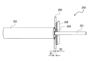
次に、図13を用いて第3実施形態にかかる放電加工方法について説明する。図13は、第3実施形態にかかる放電加工方法の模式図を示す。ここでは、第2実施形態にかかる放電加工方法と同様に、被加工体200(図10参照)を放電加工し、加工体230(図12参照)を形成する場合について説明する。第3実施形態にかかる放電加工方法は、第2実施形態にかかる放電加工方法と共通する構成について、同一の符号を付して、説明する。
(Third embodiment)
Next, an electric discharge machining method according to the third embodiment will be described with reference to FIG. FIG. 13 is a schematic diagram of an electric discharge machining method according to the third embodiment. Here, as in the electric discharge machining method according to the second embodiment, a case will be described in which the workpiece 200 (see FIG. 10) is subjected to electric discharge machining to form the workpiece 230 (see FIG. 12). The electrical discharge machining method according to the third embodiment will be described with the same reference numerals assigned to the same configuration as the electrical discharge machining method according to the second embodiment.
図13に示すように、遮蔽板308を用いて、接続部202を放電加工して、仕上部201を形成する。遮蔽板308は、仕上部201を通過させるための通過孔309を備える板状体である。遮蔽板308は、仕上部201を通過孔309に通過させる。また、遮蔽板308を接続部202と対向するように配置する。また、ワイヤ電極290を遮蔽板308と接続部202との間に配置して、接続部202の被加工部204を放電加工して、仕上部201を形成する。
As shown in FIG. 13, the
このような放電加工は、遮蔽板308とワイヤ電極290とを備える放電加工機を利用することができる。放電加工機は、遮蔽板308とワイヤ電極290とを操作する操作機構を備える。操作機構は、ワイヤ電極290の動きに応じて、遮蔽板308を操作すると好ましい。また、操作機構は、被加工体200と遮蔽板308とが機械的な干渉を起こさないように、遮蔽板308を操作すると好ましい。
For such electric discharge machining, an electric discharge machine including a
ここで、接続部202の被加工部204が放電加工により加工され、加工屑が被加工部203から発生する。遮蔽板308が配置されているので、加工屑が遮蔽板308により進行を妨害されて、仕上部201に到達しにくい。すなわち、加工屑は、仕上部201に付着しにくいのである。
Here, the processed
接続部202の被加工部204とワイヤ電極290との距離D1は、1〜2μmである場合、遮蔽板308とワイヤ電極290との距離D2は、4〜6μmであると好ましく、さらに好ましくは4.5〜5.5μmである。遮蔽板308とワイヤ電極290との電位差がゼロであると好ましい。これらによれば、遮蔽板308とワイヤ電極290との間にアークを発生させることなく、接続部202の被加工部204とワイヤ電極290との間にアークを発生させて、放電加工をより安定して行うことができる。
When the distance D1 between the processed
以上より、本実施形態によれば、図11に示すように、加工体230を得ることができる。加工体230は、仕上部201と、仕上部201に連続的につながった接続部202とを、有する。放電加工による加工屑が仕上部201に付着にくいので、仕上部201は、仕上した直後の表面粗さや寸法精度を維持している。また、本実施形態によれば、多種多様な放電加工機において適用することができる。また、本実施形態によれば、仕上げ加工をすることなく、粗加工しただけで、良好な面粗さや寸法精度が得られる。つまり、仕上げ加工と粗加工とによる工程を1回の加工工程だけで行うことができる。
As described above, according to the present embodiment, the processed
なお、上記した第1実施形態では、被加工体をプローブ形状に加工したが、多種多様な形状に加工してもよい。例えば、仕上部を含む加工体であれば、どのようなもので加工することができる。このような加工体として、例えば、パンチやダイなどの金型が挙げられる。 In the above-described first embodiment, the workpiece is processed into a probe shape, but may be processed into various shapes. For example, if it is a processed body including a finish, it can be processed with any object. Examples of such a processed body include a mold such as a punch or a die.
100、200 被加工体、 101 先端部、 102、202 接続部、 203、204 被加工部、 111 粗形状部、 112 傾斜部、
121、201 仕上部、 122 軸部、 130 プローブ、
230 加工体、 190、290 ワイヤ電極、
308 遮蔽板、 309 通過孔
100, 200 workpiece, 101 tip, 102, 202 connecting portion, 203, 204 workpiece, 111 rough shape portion, 112 inclined portion,
121, 201 Finish, 122 Shaft, 130 Probe,
230 workpieces, 190, 290 wire electrodes,
308 Shield plate, 309 Passing hole
Claims (4)
先端部と、前記先端部に連続的につながった接続部と、を有する棒状の被加工体を加工して、仕上部と、前記仕上部に連続的につながった軸部と、を有する加工体を得る加工方法であって、
前記接続部を、前記先端部から離れるにつれて断面積が連続的に増加する形状に加工する工程と、
前記先端部を仕上げして、前記仕上部を形成する工程と、
前記接続部を放電加工して、前記軸部を形成する工程と、を含む放電加工方法。 Using an electric discharge machine with wire electrodes,
A workpiece having a finish and a shaft continuously connected to the finish by processing a rod-like workpiece having a tip and a connection continuously connected to the tip. A processing method for obtaining
Processing the connection part into a shape in which a cross-sectional area continuously increases as the distance from the tip part increases;
Finishing the tip and forming the finish;
Electric discharge machining the connection portion to form the shaft portion.
すでに仕上げされた仕上部と、前記仕上部に連続的につながった接続部とを有する棒状の被加工体を放電加工して、前記仕上部と、前記仕上部に連続的につながった軸部とを有する加工体を得る放電加工方法であって、
前記ワイヤ電極を前記被加工体の軸線に対して傾斜させるように張りつつ前記接続部に接近させて、前記接続部を放電加工して、前記軸部を形成する放電加工方法。 Using an electric discharge machine with wire electrodes,
An electrical discharge machining is performed on a rod-like workpiece having a finished finish and a connection portion continuously connected to the finish, and the finish and a shaft portion continuously connected to the finish. An electric discharge machining method for obtaining a processed body having:
An electric discharge machining method of forming the shaft portion by causing the wire electrode to approach the connection portion while being inclined so as to be inclined with respect to the axis of the workpiece, and to discharge-process the connection portion.
すでに仕上げされた仕上部と、前記仕上部に連続的につながった接続部とを有する棒状の被加工体を放電加工して、前記仕上部と、前記仕上部に連続的につながった軸部と、を有する加工体を得る放電加工方法であって、
遮蔽板を前記接続部と対向するように配置するとともに、
前記ワイヤ電極を前記遮蔽板と前記接続部との間に配置して、前記接続部を放電加工して、前記軸部を形成する放電加工方法。 Using an electric discharge machine with wire electrodes,
An electrical discharge machining is performed on a rod-like workpiece having a finished finish and a connection portion continuously connected to the finish, and the finish and a shaft portion continuously connected to the finish. An electric discharge machining method for obtaining a workpiece having
While arranging the shielding plate to face the connection portion,
An electric discharge machining method in which the wire electrode is disposed between the shielding plate and the connection portion, the connection portion is subjected to electric discharge machining, and the shaft portion is formed.
Priority Applications (1)
| Application Number | Priority Date | Filing Date | Title |
|---|---|---|---|
| JP2013120870A JP6153780B2 (en) | 2013-06-07 | 2013-06-07 | EDM method |
Applications Claiming Priority (1)
| Application Number | Priority Date | Filing Date | Title |
|---|---|---|---|
| JP2013120870A JP6153780B2 (en) | 2013-06-07 | 2013-06-07 | EDM method |
Publications (2)
| Publication Number | Publication Date |
|---|---|
| JP2014237191A true JP2014237191A (en) | 2014-12-18 |
| JP6153780B2 JP6153780B2 (en) | 2017-06-28 |
Family
ID=52134822
Family Applications (1)
| Application Number | Title | Priority Date | Filing Date |
|---|---|---|---|
| JP2013120870A Active JP6153780B2 (en) | 2013-06-07 | 2013-06-07 | EDM method |
Country Status (1)
| Country | Link |
|---|---|
| JP (1) | JP6153780B2 (en) |
Cited By (1)
| Publication number | Priority date | Publication date | Assignee | Title |
|---|---|---|---|---|
| DE102019200568A1 (en) | 2018-01-19 | 2019-07-25 | Mitutoyo Corporation | METHOD FOR PRODUCING A KEY |
Citations (6)
| Publication number | Priority date | Publication date | Assignee | Title |
|---|---|---|---|---|
| JPS57126931U (en) * | 1981-02-04 | 1982-08-07 | ||
| JPS597525A (en) * | 1982-07-01 | 1984-01-14 | Mitsubishi Electric Corp | Wire-cut electric discharge machining |
| JPS6150716A (en) * | 1984-05-25 | 1986-03-13 | フイルマ ア−エ−ゲ−−エロ−テルン ゲゼルシヤフト ミツト ベシユレンクテル ハフツング | Method and device for electrolytically carving groove in extremely small width |
| JPH09272058A (en) * | 1996-04-08 | 1997-10-21 | Central Japan Railway Co | Polishing device for vehicle with window shield |
| JP2005096033A (en) * | 2003-09-25 | 2005-04-14 | Mitsutoyo Corp | Probe machining method, probe, measuring machine, and electric discharge machine |
| JP2006231481A (en) * | 2005-02-25 | 2006-09-07 | Mitsutoyo Corp | Product machining method, and probe machining method |
-
2013
- 2013-06-07 JP JP2013120870A patent/JP6153780B2/en active Active
Patent Citations (6)
| Publication number | Priority date | Publication date | Assignee | Title |
|---|---|---|---|---|
| JPS57126931U (en) * | 1981-02-04 | 1982-08-07 | ||
| JPS597525A (en) * | 1982-07-01 | 1984-01-14 | Mitsubishi Electric Corp | Wire-cut electric discharge machining |
| JPS6150716A (en) * | 1984-05-25 | 1986-03-13 | フイルマ ア−エ−ゲ−−エロ−テルン ゲゼルシヤフト ミツト ベシユレンクテル ハフツング | Method and device for electrolytically carving groove in extremely small width |
| JPH09272058A (en) * | 1996-04-08 | 1997-10-21 | Central Japan Railway Co | Polishing device for vehicle with window shield |
| JP2005096033A (en) * | 2003-09-25 | 2005-04-14 | Mitsutoyo Corp | Probe machining method, probe, measuring machine, and electric discharge machine |
| JP2006231481A (en) * | 2005-02-25 | 2006-09-07 | Mitsutoyo Corp | Product machining method, and probe machining method |
Cited By (1)
| Publication number | Priority date | Publication date | Assignee | Title |
|---|---|---|---|---|
| DE102019200568A1 (en) | 2018-01-19 | 2019-07-25 | Mitutoyo Corporation | METHOD FOR PRODUCING A KEY |
Also Published As
| Publication number | Publication date |
|---|---|
| JP6153780B2 (en) | 2017-06-28 |
Similar Documents
| Publication | Publication Date | Title |
|---|---|---|
| CN104625277B (en) | A kind of numerical control electric spark deposits handle of a knife | |
| JP6616383B2 (en) | Control device for wire electric discharge machine and control method for wire electric discharge machine | |
| JP6435330B2 (en) | Metal forming equipment | |
| CN104801795A (en) | Line-electrode radial reciprocating vibrating type micro electrolyzing cutting processing method | |
| CN101664833A (en) | Device and method for processing complex curved surface for shaping electric discharge machine (EDM) | |
| Laxminarayana | Optimization of electrode tool wear in micro holes machining by die sinker EDM using Taguchi approach | |
| CN112958862B (en) | Wire electrode track compensation method for electrospark wire-electrode cutting processing | |
| JP6153780B2 (en) | EDM method | |
| CN104475887A (en) | Electric spark grinding machining method for low-rigidity circular conical surface rod part | |
| US20160045968A1 (en) | Apparatus for electrochemically machining a metallic workpiece | |
| CN103862121B (en) | A kind of novel numerical control electric spark wire cutting method and device | |
| CN103008801B (en) | Discharge machining process adopting indirect neutral method | |
| CN109226917B (en) | Surface roughening method based on electric discharge machining | |
| CN202498273U (en) | Electrode array assembly for electric spark processing apparatus | |
| CN106944684A (en) | A kind of micro rod side surface platform processing method | |
| CN106536107B (en) | Discharge-treating method and discharging processing machine | |
| Sabur et al. | Micro-EDM for micro-channel fabrication on nonconductive ZrO2 ceramic | |
| KR101477183B1 (en) | Method for Manufacturing Micro-nozzle | |
| KR20130060797A (en) | Fabrication method of micro tool electrodes using wear ratio | |
| JP3884210B2 (en) | Processing method and apparatus using wire electrode | |
| JPWO2000067941A1 (en) | Discharge surface treatment method and device, and electrode for discharge surface treatment | |
| JPH10113742A (en) | Manufacture of collet for tig torch | |
| CN113600940B (en) | Electrode structure | |
| Verma et al. | A Review on Different Process Parameter in Wire Electric Discharge Machining | |
| Hsia | Improvement of Surface Roughness in Electrical Discharge Machining by Using Ultrasonic Auxiliary Electrode |
Legal Events
| Date | Code | Title | Description |
|---|---|---|---|
| A621 | Written request for application examination |
Free format text: JAPANESE INTERMEDIATE CODE: A621 Effective date: 20160516 |
|
| A977 | Report on retrieval |
Free format text: JAPANESE INTERMEDIATE CODE: A971007 Effective date: 20170316 |
|
| A131 | Notification of reasons for refusal |
Free format text: JAPANESE INTERMEDIATE CODE: A131 Effective date: 20170328 |
|
| A521 | Request for written amendment filed |
Free format text: JAPANESE INTERMEDIATE CODE: A523 Effective date: 20170522 |
|
| TRDD | Decision of grant or rejection written | ||
| A01 | Written decision to grant a patent or to grant a registration (utility model) |
Free format text: JAPANESE INTERMEDIATE CODE: A01 Effective date: 20170530 |
|
| A61 | First payment of annual fees (during grant procedure) |
Free format text: JAPANESE INTERMEDIATE CODE: A61 Effective date: 20170531 |
|
| R150 | Certificate of patent or registration of utility model |
Ref document number: 6153780 Country of ref document: JP Free format text: JAPANESE INTERMEDIATE CODE: R150 |
|
| R250 | Receipt of annual fees |
Free format text: JAPANESE INTERMEDIATE CODE: R250 |
|
| R250 | Receipt of annual fees |
Free format text: JAPANESE INTERMEDIATE CODE: R250 |