JP2014509249A - Apparatus and method for purifying air from undesirable components and removing such components - Google Patents
Apparatus and method for purifying air from undesirable components and removing such components Download PDFInfo
- Publication number
- JP2014509249A JP2014509249A JP2013548866A JP2013548866A JP2014509249A JP 2014509249 A JP2014509249 A JP 2014509249A JP 2013548866 A JP2013548866 A JP 2013548866A JP 2013548866 A JP2013548866 A JP 2013548866A JP 2014509249 A JP2014509249 A JP 2014509249A
- Authority
- JP
- Japan
- Prior art keywords
- air
- purified
- water dust
- zone
- water
- Prior art date
- Legal status (The legal status is an assumption and is not a legal conclusion. Google has not performed a legal analysis and makes no representation as to the accuracy of the status listed.)
- Granted
Links
- 238000000034 method Methods 0.000 title claims description 24
- XLYOFNOQVPJJNP-UHFFFAOYSA-N water Substances O XLYOFNOQVPJJNP-UHFFFAOYSA-N 0.000 claims abstract description 46
- 239000000428 dust Substances 0.000 claims abstract description 37
- 239000007789 gas Substances 0.000 claims abstract description 29
- 238000000746 purification Methods 0.000 claims abstract description 27
- 150000002500 ions Chemical class 0.000 claims abstract description 26
- MHAJPDPJQMAIIY-UHFFFAOYSA-N Hydrogen peroxide Chemical compound OO MHAJPDPJQMAIIY-UHFFFAOYSA-N 0.000 claims abstract description 16
- 239000002245 particle Substances 0.000 claims abstract description 15
- 244000005700 microbiome Species 0.000 claims abstract description 9
- ZCYVEMRRCGMTRW-UHFFFAOYSA-N 7553-56-2 Chemical compound [I] ZCYVEMRRCGMTRW-UHFFFAOYSA-N 0.000 claims abstract description 3
- CBENFWSGALASAD-UHFFFAOYSA-N Ozone Chemical compound [O-][O+]=O CBENFWSGALASAD-UHFFFAOYSA-N 0.000 claims abstract description 3
- 239000011630 iodine Substances 0.000 claims abstract description 3
- 229910052740 iodine Inorganic materials 0.000 claims abstract description 3
- 239000013618 particulate matter Substances 0.000 claims abstract description 3
- 230000003647 oxidation Effects 0.000 claims description 8
- 238000007254 oxidation reaction Methods 0.000 claims description 8
- 239000002105 nanoparticle Substances 0.000 claims description 7
- 239000000126 substance Substances 0.000 claims description 6
- 241000894006 Bacteria Species 0.000 claims description 3
- 241000700605 Viruses Species 0.000 claims description 3
- 230000000813 microbial effect Effects 0.000 claims description 3
- 230000005611 electricity Effects 0.000 claims description 2
- QGZKDVFQNNGYKY-UHFFFAOYSA-N Ammonia Chemical compound N QGZKDVFQNNGYKY-UHFFFAOYSA-N 0.000 claims 2
- CURLTUGMZLYLDI-UHFFFAOYSA-N Carbon dioxide Chemical compound O=C=O CURLTUGMZLYLDI-UHFFFAOYSA-N 0.000 claims 2
- 241000233866 Fungi Species 0.000 claims 1
- 229910021529 ammonia Inorganic materials 0.000 claims 1
- 239000001569 carbon dioxide Substances 0.000 claims 1
- 229910002092 carbon dioxide Inorganic materials 0.000 claims 1
- 238000001514 detection method Methods 0.000 claims 1
- 239000000463 material Substances 0.000 claims 1
- 239000000835 fiber Substances 0.000 abstract description 2
- 238000001914 filtration Methods 0.000 abstract description 2
- 230000002285 radioactive effect Effects 0.000 abstract description 2
- 235000019645 odor Nutrition 0.000 description 7
- 238000005422 blasting Methods 0.000 description 4
- 244000052769 pathogen Species 0.000 description 4
- 238000004887 air purification Methods 0.000 description 3
- 239000007800 oxidant agent Substances 0.000 description 3
- 238000004140 cleaning Methods 0.000 description 2
- 238000002474 experimental method Methods 0.000 description 2
- 238000000926 separation method Methods 0.000 description 2
- 239000000443 aerosol Substances 0.000 description 1
- 244000052616 bacterial pathogen Species 0.000 description 1
- 239000003899 bactericide agent Substances 0.000 description 1
- 239000000356 contaminant Substances 0.000 description 1
- 238000005265 energy consumption Methods 0.000 description 1
- 239000000383 hazardous chemical Substances 0.000 description 1
- 231100000206 health hazard Toxicity 0.000 description 1
- 238000012423 maintenance Methods 0.000 description 1
- 244000000010 microbial pathogen Species 0.000 description 1
- 230000001590 oxidative effect Effects 0.000 description 1
- 238000012360 testing method Methods 0.000 description 1
- 238000013519 translation Methods 0.000 description 1
Images
Classifications
-
- B—PERFORMING OPERATIONS; TRANSPORTING
- B03—SEPARATION OF SOLID MATERIALS USING LIQUIDS OR USING PNEUMATIC TABLES OR JIGS; MAGNETIC OR ELECTROSTATIC SEPARATION OF SOLID MATERIALS FROM SOLID MATERIALS OR FLUIDS; SEPARATION BY HIGH-VOLTAGE ELECTRIC FIELDS
- B03C—MAGNETIC OR ELECTROSTATIC SEPARATION OF SOLID MATERIALS FROM SOLID MATERIALS OR FLUIDS; SEPARATION BY HIGH-VOLTAGE ELECTRIC FIELDS
- B03C3/00—Separating dispersed particles from gases or vapour, e.g. air, by electrostatic effect
- B03C3/01—Pretreatment of the gases prior to electrostatic precipitation
- B03C3/014—Addition of water; Heat exchange, e.g. by condensation
-
- B—PERFORMING OPERATIONS; TRANSPORTING
- B01—PHYSICAL OR CHEMICAL PROCESSES OR APPARATUS IN GENERAL
- B01D—SEPARATION
- B01D50/00—Combinations of methods or devices for separating particles from gases or vapours
-
- B—PERFORMING OPERATIONS; TRANSPORTING
- B03—SEPARATION OF SOLID MATERIALS USING LIQUIDS OR USING PNEUMATIC TABLES OR JIGS; MAGNETIC OR ELECTROSTATIC SEPARATION OF SOLID MATERIALS FROM SOLID MATERIALS OR FLUIDS; SEPARATION BY HIGH-VOLTAGE ELECTRIC FIELDS
- B03B—SEPARATING SOLID MATERIALS USING LIQUIDS OR USING PNEUMATIC TABLES OR JIGS
- B03B11/00—Feed or discharge devices integral with washing or wet-separating equipment
-
- B—PERFORMING OPERATIONS; TRANSPORTING
- B03—SEPARATION OF SOLID MATERIALS USING LIQUIDS OR USING PNEUMATIC TABLES OR JIGS; MAGNETIC OR ELECTROSTATIC SEPARATION OF SOLID MATERIALS FROM SOLID MATERIALS OR FLUIDS; SEPARATION BY HIGH-VOLTAGE ELECTRIC FIELDS
- B03C—MAGNETIC OR ELECTROSTATIC SEPARATION OF SOLID MATERIALS FROM SOLID MATERIALS OR FLUIDS; SEPARATION BY HIGH-VOLTAGE ELECTRIC FIELDS
- B03C3/00—Separating dispersed particles from gases or vapour, e.g. air, by electrostatic effect
- B03C3/02—Plant or installations having external electricity supply
- B03C3/16—Plant or installations having external electricity supply wet type
-
- B—PERFORMING OPERATIONS; TRANSPORTING
- B03—SEPARATION OF SOLID MATERIALS USING LIQUIDS OR USING PNEUMATIC TABLES OR JIGS; MAGNETIC OR ELECTROSTATIC SEPARATION OF SOLID MATERIALS FROM SOLID MATERIALS OR FLUIDS; SEPARATION BY HIGH-VOLTAGE ELECTRIC FIELDS
- B03C—MAGNETIC OR ELECTROSTATIC SEPARATION OF SOLID MATERIALS FROM SOLID MATERIALS OR FLUIDS; SEPARATION BY HIGH-VOLTAGE ELECTRIC FIELDS
- B03C3/00—Separating dispersed particles from gases or vapour, e.g. air, by electrostatic effect
- B03C3/34—Constructional details or accessories or operation thereof
- B03C3/38—Particle charging or ionising stations, e.g. using electric discharge, radioactive radiation or flames
-
- B—PERFORMING OPERATIONS; TRANSPORTING
- B03—SEPARATION OF SOLID MATERIALS USING LIQUIDS OR USING PNEUMATIC TABLES OR JIGS; MAGNETIC OR ELECTROSTATIC SEPARATION OF SOLID MATERIALS FROM SOLID MATERIALS OR FLUIDS; SEPARATION BY HIGH-VOLTAGE ELECTRIC FIELDS
- B03C—MAGNETIC OR ELECTROSTATIC SEPARATION OF SOLID MATERIALS FROM SOLID MATERIALS OR FLUIDS; SEPARATION BY HIGH-VOLTAGE ELECTRIC FIELDS
- B03C3/00—Separating dispersed particles from gases or vapour, e.g. air, by electrostatic effect
- B03C3/34—Constructional details or accessories or operation thereof
- B03C3/38—Particle charging or ionising stations, e.g. using electric discharge, radioactive radiation or flames
- B03C3/383—Particle charging or ionising stations, e.g. using electric discharge, radioactive radiation or flames using radiation
-
- B—PERFORMING OPERATIONS; TRANSPORTING
- B03—SEPARATION OF SOLID MATERIALS USING LIQUIDS OR USING PNEUMATIC TABLES OR JIGS; MAGNETIC OR ELECTROSTATIC SEPARATION OF SOLID MATERIALS FROM SOLID MATERIALS OR FLUIDS; SEPARATION BY HIGH-VOLTAGE ELECTRIC FIELDS
- B03C—MAGNETIC OR ELECTROSTATIC SEPARATION OF SOLID MATERIALS FROM SOLID MATERIALS OR FLUIDS; SEPARATION BY HIGH-VOLTAGE ELECTRIC FIELDS
- B03C3/00—Separating dispersed particles from gases or vapour, e.g. air, by electrostatic effect
- B03C3/34—Constructional details or accessories or operation thereof
- B03C3/40—Electrode constructions
- B03C3/41—Ionising-electrodes
-
- B—PERFORMING OPERATIONS; TRANSPORTING
- B03—SEPARATION OF SOLID MATERIALS USING LIQUIDS OR USING PNEUMATIC TABLES OR JIGS; MAGNETIC OR ELECTROSTATIC SEPARATION OF SOLID MATERIALS FROM SOLID MATERIALS OR FLUIDS; SEPARATION BY HIGH-VOLTAGE ELECTRIC FIELDS
- B03C—MAGNETIC OR ELECTROSTATIC SEPARATION OF SOLID MATERIALS FROM SOLID MATERIALS OR FLUIDS; SEPARATION BY HIGH-VOLTAGE ELECTRIC FIELDS
- B03C3/00—Separating dispersed particles from gases or vapour, e.g. air, by electrostatic effect
- B03C3/34—Constructional details or accessories or operation thereof
- B03C3/40—Electrode constructions
- B03C3/45—Collecting-electrodes
- B03C3/47—Collecting-electrodes flat, e.g. plates, discs, gratings
-
- B—PERFORMING OPERATIONS; TRANSPORTING
- B01—PHYSICAL OR CHEMICAL PROCESSES OR APPARATUS IN GENERAL
- B01D—SEPARATION
- B01D47/00—Separating dispersed particles from gases, air or vapours by liquid as separating agent
- B01D47/06—Spray cleaning
-
- B—PERFORMING OPERATIONS; TRANSPORTING
- B03—SEPARATION OF SOLID MATERIALS USING LIQUIDS OR USING PNEUMATIC TABLES OR JIGS; MAGNETIC OR ELECTROSTATIC SEPARATION OF SOLID MATERIALS FROM SOLID MATERIALS OR FLUIDS; SEPARATION BY HIGH-VOLTAGE ELECTRIC FIELDS
- B03C—MAGNETIC OR ELECTROSTATIC SEPARATION OF SOLID MATERIALS FROM SOLID MATERIALS OR FLUIDS; SEPARATION BY HIGH-VOLTAGE ELECTRIC FIELDS
- B03C2201/00—Details of magnetic or electrostatic separation
- B03C2201/10—Ionising electrode with two or more serrated ends or sides
-
- B—PERFORMING OPERATIONS; TRANSPORTING
- B03—SEPARATION OF SOLID MATERIALS USING LIQUIDS OR USING PNEUMATIC TABLES OR JIGS; MAGNETIC OR ELECTROSTATIC SEPARATION OF SOLID MATERIALS FROM SOLID MATERIALS OR FLUIDS; SEPARATION BY HIGH-VOLTAGE ELECTRIC FIELDS
- B03C—MAGNETIC OR ELECTROSTATIC SEPARATION OF SOLID MATERIALS FROM SOLID MATERIALS OR FLUIDS; SEPARATION BY HIGH-VOLTAGE ELECTRIC FIELDS
- B03C2201/00—Details of magnetic or electrostatic separation
- B03C2201/24—Details of magnetic or electrostatic separation for measuring or calculating of parameters, e.g. efficiency
-
- B—PERFORMING OPERATIONS; TRANSPORTING
- B03—SEPARATION OF SOLID MATERIALS USING LIQUIDS OR USING PNEUMATIC TABLES OR JIGS; MAGNETIC OR ELECTROSTATIC SEPARATION OF SOLID MATERIALS FROM SOLID MATERIALS OR FLUIDS; SEPARATION BY HIGH-VOLTAGE ELECTRIC FIELDS
- B03C—MAGNETIC OR ELECTROSTATIC SEPARATION OF SOLID MATERIALS FROM SOLID MATERIALS OR FLUIDS; SEPARATION BY HIGH-VOLTAGE ELECTRIC FIELDS
- B03C2201/00—Details of magnetic or electrostatic separation
- B03C2201/32—Checking the quality of the result or the well-functioning of the device
-
- Y—GENERAL TAGGING OF NEW TECHNOLOGICAL DEVELOPMENTS; GENERAL TAGGING OF CROSS-SECTIONAL TECHNOLOGIES SPANNING OVER SEVERAL SECTIONS OF THE IPC; TECHNICAL SUBJECTS COVERED BY FORMER USPC CROSS-REFERENCE ART COLLECTIONS [XRACs] AND DIGESTS
- Y02—TECHNOLOGIES OR APPLICATIONS FOR MITIGATION OR ADAPTATION AGAINST CLIMATE CHANGE
- Y02A—TECHNOLOGIES FOR ADAPTATION TO CLIMATE CHANGE
- Y02A50/00—TECHNOLOGIES FOR ADAPTATION TO CLIMATE CHANGE in human health protection, e.g. against extreme weather
- Y02A50/20—Air quality improvement or preservation, e.g. vehicle emission control or emission reduction by using catalytic converters
- Y02A50/2351—Atmospheric particulate matter [PM], e.g. carbon smoke microparticles, smog, aerosol particles, dust
Landscapes
- Chemical & Material Sciences (AREA)
- Chemical Kinetics & Catalysis (AREA)
- Health & Medical Sciences (AREA)
- General Health & Medical Sciences (AREA)
- Toxicology (AREA)
- Disinfection, Sterilisation Or Deodorisation Of Air (AREA)
- Electrostatic Separation (AREA)
- Treating Waste Gases (AREA)
- Separation Of Particles Using Liquids (AREA)
- Filtering Of Dispersed Particles In Gases (AREA)
Abstract
本発明は、好ましくないガスや粒子、原子力発電所の場合は、放射性粒子やヨウ素ガス、から空気を浄化し、更に、微生物の駆除と空気からの除去のための装置に関する。前記装置は、浄化対象空気がそれを通って流れるように構成された浄化チャンバから成る。構造的に接地された浄化チャンバ内において、イオン化された空気(1)は、過酸化水素によって、またオゾンを発生するためにイオン化の電圧レベルを高めることによって、酸化可能な水ダストまたは蒸気へ導かれ、更に、収集面(9)に向けられ、それと共に小滴および粒子状物質、更に、それらに結合したガス成分を運ぶ連続イオンジェット流を作り出す高電圧作動イオン・ブラスト・チップ(8)へと導かれる。前記浄化装置の形状と容積は浄化対象空気の量によって決まる。その使用においても、繊維濾過と比較してエネルギも大幅に節約される。 The present invention relates to an apparatus for purifying air from undesirable gases and particles, in the case of nuclear power plants, radioactive particles and iodine gas, and also for the removal of microorganisms and removal from the air. The apparatus comprises a purification chamber configured to allow air to be purified to flow therethrough. Within the structurally grounded purification chamber, ionized air (1) is directed to oxidizable water dust or vapor by hydrogen peroxide and by increasing the voltage level of ionization to generate ozone. To a high voltage working ion blast tip (8) that creates a continuous ion jet stream that is directed towards the collection surface (9) and carries with it droplets and particulate matter, and further gas components coupled to them. It is guided. The shape and volume of the purification device are determined by the amount of air to be purified. Even in its use, energy is also saved significantly compared to fiber filtration.
Description
本発明は、ナノサイズまたはそれ上のサイズの好ましくないガス、微生物、小滴、粒子から空気を浄化するための装置であって、それを通って浄化対象空気が流れるように構成されるとともに、浄化対象空気が水ダストまたは蒸気を通して流されるように構成されるゾーンを備える浄化チャンバと、収集面に向けられたイオンブラストチップを備えるイオンブラストチャンバとを有する装置であって、浄化対象空気中に含まれ、且つ前記イオンブラストチップから噴出されるイオン噴流を介して供給される小滴または粒子状物質が、接地された前記収集面に向けて投げ出されることによりこれら収集面上に収集された物質が前記浄化チャンバの底部へと流下し、そこから、更に、浄化済み空気が前記浄化チャンバを離れると同時に排出部へと流れるように構成された装置に関する。 The present invention is an apparatus for purifying air from nano-sized or above unfavorable gases, microorganisms, droplets, particles, configured to flow air to be purified therethrough, An apparatus having a purification chamber with a zone configured to allow the air to be purified to flow through water dust or steam, and an ion blast chamber with an ion blast tip directed to the collection surface, wherein the air in the air to be purified Substances collected on these collection surfaces by being thrown toward the grounded collection surface, which are contained and supplied via an ion jet ejected from the ion blast tip Flows down to the bottom of the purification chamber, from which further purified air leaves the purification chamber and at the same time to the discharge section. About the apparatus configured as.
本発明は、更に、好ましくないガス、微生物、ナノサイズまたはそれ以上のサイズの液滴粒子から空気を浄化するための方法であって、浄化対象空気を水ダストまたは蒸気のゾーンと、次に、イオンブラストチャンバとを通過するように案内する工程を有し、浄化対象空気中に含まれイオン放出チップから噴出されるイオン噴流を介して供給される小滴または粒子状物質が、接地された収集面に向けて投げ出され、前記収集面上に収集された物質が前記浄化チャンバの底部へと流下し、そこから、更に、浄化済み空気が放出されると同時に排出部へと流れる、方法にも関する。 The present invention further provides a method for purifying air from undesirable gas, microorganisms, nano-sized or larger droplet particles, wherein the air to be purified is a water dust or vapor zone, and A step of guiding the ion blast chamber through the ion blast chamber, and collecting the grounded droplets or particulate matter contained in the air to be purified and supplied via an ion jet ejected from an ion ejection tip. In the method, the substance thrown toward the surface and collected on the collecting surface flows down to the bottom of the purification chamber, and further, the purified air is discharged to the discharge part at the same time. Related.
実施とテストとによって、1ミリメートル以上のサイズの粒子のみならず、ナノサイズの粒子や蒸気もイオンブラスト法によって分離することが可能であることが示されている。公知の方法では、臭気とガスの分離は問題があった。イオンブラスト法等のそれ自身公知の空気浄化解決構成は数多くのフィンランドおよび米国特許に見出すことができる。 Implementation and testing have shown that not only particles with a size of 1 millimeter or more, but also nano-sized particles and vapors can be separated by ion blasting. In known methods, the separation of odor and gas has been problematic. Air purification solutions known per se, such as ion blasting, can be found in numerous Finnish and US patents.
例えば、フィンランド特許公報FI−116122に対応の文献WO2005/092510において、空気から好ましくないガスと粒子とを除去するためのそれ自身公知の装置と方法とが開示されている。この文献のページ1,32−33行目には、「実験によって、本発明の装置と方法とによって浄化対象空気から臭気を効果的に除去することが可能であることが示された」と記載されている。 For example, document WO 2005/092510 corresponding to Finnish patent publication FI-116122 discloses a device and method known per se for removing undesirable gases and particles from air. On pages 1, 32-33 of this document, “Experiment has shown that the apparatus and method of the present invention can effectively remove odor from the air to be purified”. Has been.
好ましくないガスおよび粒子から空気を浄化するための方法と装置のもう一つの例がフィンランド特許公報FI−121165に開示されている。この公報のページ2、6−11行目には、その英語翻訳文で、本発明の装置と方法は、浄化チャンバの空気導入開口部または入口ゾーンに空気のための強力な酸化ゾーンが設けられ、それによって、たとえば、過酸化水素を含有する水ダストによる酸化が提供されることを特徴としている、記載されている。酸化によって、臭気の除去に加えて、例えば、ウィルス、バクテリア、胞子といった病原菌、及びその他の微生物の駆除、収集面上への粒子状汚染物質との無生物物質の除去を達成することが可能である。しかしながら、強力で不快な臭気が或程度装置を通過し十分に強力な酸化物質を使用することは常に可能であるとは限らない。 Another example of a method and apparatus for purifying air from undesirable gases and particles is disclosed in Finnish Patent Publication FI-121165. On page 2, lines 6-11 of this publication, in its English translation, the apparatus and method of the present invention is provided with a strong oxidation zone for air in the air inlet opening or inlet zone of the purification chamber. Which is characterized, for example, by providing oxidation with water dust containing hydrogen peroxide. Oxidation can achieve, in addition to removing odors, for example, eliminating pathogens such as viruses, bacteria, spores, and other microorganisms, and removing inanimate substances with particulate contaminants on the collection surface. . However, it is not always possible to use a strong enough oxidant with some strong and unpleasant odor passing through the device.
本発明の課題は、これらの欠点を解消し、強力な酸化なしで、臭気を効果的に分離することが可能な装置と方法を提供することにある。 An object of the present invention is to provide an apparatus and a method capable of eliminating these disadvantages and effectively separating odors without strong oxidation.
この課題は、浄化チャンバの入口端部に、浄化対象空気が水ダストまたは水蒸気ゾーンを通して案内される前にこの浄化対象空気のイオン化のためのイオン化放出チップを備えるイオン化チャンバが設けられ、更に、前記浄化チャンバの入口に、前記浄化チャンバの電気/制御センターに接続されたガスセンサが設けられ、前記センターが、前記ガスセンサからの信号に基づいて、前記イオン化の電荷の正負を判定するように構成されていることを特徴とする、装置と方法とによって達成される。これにより、空気の強力なイオン化が前記水ダストゾーンの前の浄化チャンバの入口ゾーンにおいて行われ、前記ガスセンサからの信号に基づいて、イオン化を、オゾンが所望のレベルで発生される電圧レベルに制御することも可能となる。 The object is to provide at the inlet end of the purification chamber an ionization chamber comprising an ionization discharge tip for ionization of the air to be purified before it is guided through the water dust or water vapor zone, A gas sensor connected to an electric / control center of the purification chamber is provided at the inlet of the purification chamber, and the center is configured to determine whether the ionization charge is positive or negative based on a signal from the gas sensor. This is achieved by an apparatus and method characterized in that: Thereby, strong ionization of air is performed in the inlet zone of the purification chamber in front of the water dust zone, and based on the signal from the gas sensor, ionization is controlled to a voltage level at which ozone is generated at a desired level. It is also possible to do.
前記水ダストゾーンの水ダストとして使用される水は、好ましくは、ガスの除去と微生物の駆除を強化するべく過酸化水素によって酸化することができる。イオン化装置が非常に安価でしかもその運転コストが非常に低いことによって、ガスの効果的な除去と、例えばウィルス、バクテリア、胞子などの病原菌およびその他の微生物の駆除を、水ダストの低レベルの酸化によってもすでに達成することが可能である。 The water used as water dust in the water dust zone can preferably be oxidized with hydrogen peroxide to enhance gas removal and microbial control. The ionizer is very inexpensive and its operating cost is very low, which effectively removes gas and eliminates pathogens such as viruses, bacteria, spores and other microorganisms, and lowers the level of water dust oxidation. Can already be achieved.
浄化チャンバの入口に設けられたガスセンサからの信号に基づいて、電気/制御センターが、水ダストゾーンにおける水ダストの酸化必要度を判断することも可能である。前記水ダストゾーンの水ダストの小滴サイズは、好ましくは、20μm未満である。 Based on a signal from a gas sensor provided at the inlet of the purification chamber, the electricity / control center can determine the necessity of water dust oxidation in the water dust zone. The droplet size of the water dust in the water dust zone is preferably less than 20 μm.
本発明において、水ダストに代えて、たとえば+200℃の温度を有する蒸気を使用することも可能である。 In the present invention, steam having a temperature of, for example, + 200 ° C. can be used instead of water dust.
実験により、本発明の前記装置と方法によって、浄化対象空気から臭気を効果的に分離することが可能であることが示された。同時に、ナノサイズ以上の粒子が空気からほとんど100%除去される。 Experiments have shown that odor can be effectively separated from the air to be purified by the apparatus and method of the present invention. At the same time, almost 100% of the nano-sized particles are removed from the air.
一好適実施例に依れば、空気は、前記浄化チャンバ内に案内される前に、負または正の電荷によってイオン化される。そして荷電された空気が、必要であれば、過酸化水素やその他の酸化剤をそれに混合することが可能な前記水ダストまたは水蒸気へと案内される。20μm未満の粒子サイズの水ダストが実用的に最も有利である。イオンブラスト現象を作り出す前記浄化チャンバ内の高電圧作動チップによって、収集面への数百万のイオンの連続噴流が作り出され、それとともに、浄化対象空気から、ナノサイズ以上の浄化された粒子、小滴、病原菌、その他の微生物および好ましくないガスが取り出される。エーロゾルの荷電能力は重要ではなく、したがって、この点において、前記方法は電子フィルタと異なる。前記収集面に打ち付けられた小滴は連続的に取り除かれ、収集面から排出部に向けて下方に通過する。前記接地収集面も、実際の浄化作業を中断することなく、水洗によってクリーニングすることが可能である。 According to one preferred embodiment, the air is ionized by a negative or positive charge before being guided into the purification chamber. The charged air is then guided to the water dust or water vapor, which can be mixed with hydrogen peroxide and other oxidants, if necessary. Water dust with a particle size of less than 20 μm is most advantageous in practice. The high voltage working tip in the purification chamber that creates the ion blasting phenomenon creates a continuous jet of millions of ions to the collection surface, along with purified particles, Drops, pathogens, other microorganisms and unwanted gases are removed. The charging capacity of the aerosol is not critical and thus the method differs from an electronic filter in this respect. The droplets struck on the collecting surface are continuously removed and pass downward from the collecting surface toward the discharge portion. The ground collecting surface can also be cleaned by rinsing without interrupting the actual cleaning operation.
世界において殺菌剤として、媒体として水を含む過酸化水素が一般に使用されており、それによって病原菌及び微生物を殺すことができる。過酸化水素の使用には、他の酸化剤の使用において生じる、ガスや化学残留物質の生成などの問題がない。 As a bactericidal agent in the world, hydrogen peroxide containing water as a medium is generally used, thereby killing pathogenic bacteria and microorganisms. The use of hydrogen peroxide does not suffer from problems such as the generation of gases and chemical residues that occur with the use of other oxidants.
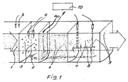
以下、添付の図面を参照して本発明を実施例によって説明するが、ここで、図1は本発明による空気浄化装置の一実施例を概略図示するものである。 Hereinafter, the present invention will be described by way of example with reference to the accompanying drawings, in which FIG. 1 schematically illustrates an example of an air purifier according to the present invention.
前記空気浄化装置は以下を有する。導入される浄化対象空気1、種々のガスを検出する複数のセンサ2。イオン化チャンバ3、その内では、浄化対象空気がイオン放出チップ4へと案内される。すべての空気処理ゾーンからの水の除去は、排出部またはタンク5へ行われる。ゾーン6、これは水ダストゾーンであって、ここでは、水ダストまたは酸化水ダストまたは水蒸気が作られる。ここで、最も好適な小滴サイズは20μm未満である。イオンブラストチャンバ7。ここでは収集面に向けられたイオンブラストチップ8からのイオン噴流が接地された収集面9に対して打ち付けられる。前記浄化チャンバの底部は水を排出部5へと案内する。電気/制御センター10は、好ましくは10kV〜36kVの負または正の電圧によって、前記イオンブラストのための、好ましくは16kV〜150kVの高電圧センターの制御に応じたイオン化のための電圧センターと、超音波発振器、または、その他のダスト発生装置、のための電流源と、ダスト装置のための自動給水装置とを有する。
The air purifier has the following. A purification target air 1 to be introduced and a plurality of sensors 2 for detecting various gases. In the ionization chamber 3, the air to be purified is guided to the ion emission tip 4. Water removal from all air treatment zones is done to the discharge or tank 5. Zone 6, which is a water dust zone, where water dust or oxidized water dust or water vapor is created. Here, the most preferred droplet size is less than 20 μm. Ion blast chamber 7. Here, an ion jet from the ion blast tip 8 directed to the collection surface is struck against the collection surface 9 that is grounded. The bottom of the purification chamber guides water to the discharge part 5. The electrical /
本発明による前記装置と方法は、空気によって運ばれる臭気、ガス、病原菌およびナノサイズ以上の粒子を空気から分離することを目的とする用途に適している。前記方法の大きな利点は、浄化対象空気の量を用途に応じて増やすことが可能であることである。前記方法および装置は、住居の特定の空気清浄と、家、ホテル、公共建築物や工場等の大きな空間の空気浄化との両方に適している。前記方法は、原子力発電所からの空気放出物中の放射性粒子とヨウ素ガスの分離に適し、これらの健康に危害を及ぼす汚染をほとんど100%浄化する。前記方法は、更に、非常にコスト効率が高く、エネルギ消費量は低く、その運転とメンテナンス費用は、繊維濾過法と比較して低い。 The device and method according to the invention are suitable for applications aimed at separating odors, gases, pathogens and nano-sized particles carried by air from air. A great advantage of the method is that the amount of air to be purified can be increased depending on the application. The method and apparatus are suitable for both specific air cleaning of residences and air purification of large spaces such as homes, hotels, public buildings and factories. The method is suitable for the separation of radioactive particles and iodine gas in air emissions from nuclear power plants, and cleans up almost 100% of these health hazards. The method is also very cost-effective, energy consumption is low, and its operation and maintenance costs are low compared to fiber filtration methods.
Claims (11)
前記浄化チャンバの入口端部に、浄化対象空気が水ダストまたは水蒸気ゾーン(6)を通して案内される前にこの浄化対象空気のイオン化のためのイオン化放出チップ(4)を備えるイオン化チャンバ(3)が設けられ、更に、前記浄化チャンバの入口に、前記浄化チャンバの電気/制御センター(10)に接続されたガスセンサ(2)が設けられ、前記センター(10)が、前記ガスセンサからの信号に基づいて、前記イオン化の電荷の正負を判定するように構成されていることを特徴とする装置。 An apparatus for purifying air from undesirable gases, microorganisms, droplets, nano-sized or larger particles, wherein the air to be purified (1) is configured to flow therethrough and is purified A purification chamber comprising a zone (6) configured to allow subject air to flow through water dust or vapor, and an ion blast chamber (7) comprising an ion blast tip (8) directed to a collection surface (9). The droplet or particulate matter contained in the air to be purified and supplied via an ion jet ejected from the ion blast tip (8) is a grounded collection surface (9). The substance collected on these collecting surfaces flows down to the bottom of the purification chamber, and further, purified air is further purified from the purification surface. When leaving the Yanba an apparatus configured to flow at the same time to a discharge portion (5),
At the inlet end of the purification chamber, an ionization chamber (3) comprising an ionization discharge tip (4) for ionization of the purification target air before the purification target air is guided through the water dust or water vapor zone (6). Further, a gas sensor (2) connected to the electricity / control center (10) of the purification chamber is provided at the inlet of the purification chamber, and the center (10) is based on a signal from the gas sensor. An apparatus configured to determine whether the ionization charge is positive or negative.
浄化対象空気(1)が、前記水ダストまたは水蒸気ゾーン(6)を通して案内される前に、イオン化され、それによって、前記浄化対象空気がガスセンサ(2)と接触するように案内されて、電気/制御センター(10)が、前記センサからの信号に基づいて前記イオン化の電荷の正負を判定することを特徴とする方法。 A method for purifying air from undesired gases, microorganisms, droplets, nano-sized or larger particles, wherein the air to be purified (1) is moved into a water dust or vapor zone (6) and then And a droplet-shaped or particulate substance that has a step of guiding it through the ion blast zone (7) and is supplied through the ion jet from the ion blast tip (8) contained in the air to be purified. Is thrown toward the grounded collection surface (9), and the material collected on the collection surface flows down to the bottom of the purification chamber from which the purified air is released and at the same time the discharge section (5) is a method that flows to
The air to be purified (1) is ionized before being guided through the water dust or water vapor zone (6), whereby the air to be purified is guided into contact with the gas sensor (2) to A method wherein the control center (10) determines whether the ionization charge is positive or negative based on a signal from the sensor.
Applications Claiming Priority (3)
| Application Number | Priority Date | Filing Date | Title |
|---|---|---|---|
| FI20110007A FI123025B (en) | 2011-01-12 | 2011-01-12 | Apparatus and method for purifying and eliminating undesirable constituents of air |
| FI20110007 | 2011-01-12 | ||
| PCT/FI2011/000037 WO2012095549A1 (en) | 2011-01-12 | 2011-07-14 | Device and method for purifying air from non-desired components and for eliminating such components |
Publications (2)
| Publication Number | Publication Date |
|---|---|
| JP2014509249A true JP2014509249A (en) | 2014-04-17 |
| JP6021821B2 JP6021821B2 (en) | 2016-11-09 |
Family
ID=43528477
Family Applications (1)
| Application Number | Title | Priority Date | Filing Date |
|---|---|---|---|
| JP2013548866A Expired - Fee Related JP6021821B2 (en) | 2011-01-12 | 2011-07-14 | Apparatus and method for purifying air from undesirable components and removing such components |
Country Status (35)
| Country | Link |
|---|---|
| US (1) | US9475065B2 (en) |
| EP (1) | EP2663403B1 (en) |
| JP (1) | JP6021821B2 (en) |
| KR (1) | KR20140030124A (en) |
| CN (1) | CN102791381B (en) |
| AU (1) | AU2011355199B2 (en) |
| BR (1) | BR112013017695B1 (en) |
| CA (1) | CA2823669C (en) |
| CL (1) | CL2013002022A1 (en) |
| CU (1) | CU20130097A7 (en) |
| CY (1) | CY1122890T1 (en) |
| DK (1) | DK2663403T3 (en) |
| EA (1) | EA024968B1 (en) |
| ES (1) | ES2791056T3 (en) |
| FI (1) | FI123025B (en) |
| GE (1) | GEP20156279B (en) |
| HR (1) | HRP20200808T2 (en) |
| HU (1) | HUE048958T2 (en) |
| IL (1) | IL227446A (en) |
| LT (1) | LT2663403T (en) |
| MA (1) | MA34893B1 (en) |
| MX (1) | MX347409B (en) |
| MY (1) | MY166128A (en) |
| NZ (1) | NZ611883A (en) |
| PH (1) | PH12013501484A1 (en) |
| PL (1) | PL2663403T3 (en) |
| PT (1) | PT2663403T (en) |
| RS (1) | RS60278B1 (en) |
| SG (1) | SG191170A1 (en) |
| SI (1) | SI2663403T1 (en) |
| SM (1) | SMT202000238T1 (en) |
| TN (1) | TN2013000228A1 (en) |
| UA (1) | UA107529C2 (en) |
| WO (1) | WO2012095549A1 (en) |
| ZA (1) | ZA201303953B (en) |
Families Citing this family (12)
| Publication number | Priority date | Publication date | Assignee | Title |
|---|---|---|---|---|
| CA2856196C (en) | 2011-12-06 | 2020-09-01 | Masco Corporation Of Indiana | Ozone distribution in a faucet |
| CN102837112B (en) * | 2012-09-10 | 2015-01-28 | 新疆威奥科技股份有限公司 | Saddle-shaped welding device capable of realizing gas shield and submerged-arc welding functions |
| CN103900155B (en) * | 2012-12-26 | 2017-06-16 | 广州市拓丰电器有限公司 | Water ion air purifier |
| CN105650750A (en) * | 2014-11-14 | 2016-06-08 | 徐千里 | Ecological type air purifier |
| KR101700431B1 (en) * | 2015-08-12 | 2017-01-26 | 주식회사 하나지엔씨 | Control apparatus and method for hybrid sterilizing system with cluster ionizer and water catch |
| WO2017112795A1 (en) | 2015-12-21 | 2017-06-29 | Delta Faucet Company | Fluid delivery system including a disinfectant device |
| CN106237780A (en) * | 2016-08-26 | 2016-12-21 | 中国石油天然气股份有限公司 | Steam injection boiler dust removal device and steam injection boiler |
| CN106178793A (en) * | 2016-09-29 | 2016-12-07 | 芜湖恒耀汽车零部件有限公司 | Automobile exhaust pipe workshop boiler waste gas purification device |
| CN107805794B (en) * | 2017-11-16 | 2024-03-15 | 温州卡耐夫电器有限公司 | Water vapor removing structure for vacuum aluminizing machine |
| US20230058655A1 (en) * | 2020-01-30 | 2023-02-23 | Ravi Kaushik | Air purifier with self-sustaining properties |
| EP4205830A1 (en) * | 2021-12-30 | 2023-07-05 | S. Martin Clemens | Technological system for eliminating floating aerosols in the ambient air of enclosed spaces |
| US20250144435A1 (en) | 2022-02-07 | 2025-05-08 | Bioengineering For The World Corporation S.L. | Cold atmospheric plasma generator and respiratory equipment for the stimulation of cellular regeneration for living beings |
Citations (12)
| Publication number | Priority date | Publication date | Assignee | Title |
|---|---|---|---|---|
| JPS6283019A (en) * | 1985-10-09 | 1987-04-16 | Isao Miyahara | Dust collector |
| JPH01123648A (en) * | 1987-11-06 | 1989-05-16 | Matsushita Seiko Co Ltd | Air cleaner device |
| JPH04194791A (en) * | 1990-11-28 | 1992-07-14 | Hitachi Ltd | How to reduce radioactive iodine |
| JPH04251132A (en) * | 1990-10-09 | 1992-09-07 | Shin Apex Boeki Kk | Negative ion air generating device |
| JPH0544959A (en) * | 1991-08-09 | 1993-02-23 | Takasago Thermal Eng Co Ltd | Air purification conditioner |
| JPH08298197A (en) * | 1995-04-26 | 1996-11-12 | Huegle Electron Kk | Ac ionizer |
| JPH09610A (en) * | 1995-06-13 | 1997-01-07 | Samsung Electron Co Ltd | Sterilization dust collector for air conditioner and control method thereof |
| JP2001310141A (en) * | 2000-02-25 | 2001-11-06 | Matsushita Seiko Co Ltd | Dust precipitator |
| JP2005075234A (en) * | 2003-09-02 | 2005-03-24 | Zexel Valeo Climate Control Corp | Air cleaner for vehicle |
| WO2005092510A1 (en) * | 2004-03-29 | 2005-10-06 | Veikko Ilmari Ilmasti | Device and method for removing undesirable gases and particles from the air |
| JP2006057942A (en) * | 2004-08-20 | 2006-03-02 | Sharp Corp | Air conditioner |
| JP2009233059A (en) * | 2008-03-26 | 2009-10-15 | Panasonic Electric Works Co Ltd | Air cleaning apparatus |
Family Cites Families (15)
| Publication number | Priority date | Publication date | Assignee | Title |
|---|---|---|---|---|
| GB556939A (en) | 1941-05-13 | 1943-10-28 | Westinghouse Electric Int Co | Improved method of and apparatus for removing dust or other foreign particles from gas or air |
| US3729898A (en) * | 1971-06-01 | 1973-05-01 | Chemical Construction Corp | Removal of entrained matter from gas streams |
| CN1057409A (en) | 1990-06-20 | 1992-01-01 | 李育春 | Ionization-type air purification device used for clearing smoke and dust |
| SI9300414A (en) * | 1993-08-04 | 1995-02-28 | Silvano Bizjak | Process for exploitation heat energy, cleaning smoked or poluted air and improvement it by ozon |
| JP2850713B2 (en) | 1993-08-12 | 1999-01-27 | 三菱化学株式会社 | Optical information recording medium |
| US5669946A (en) * | 1996-01-26 | 1997-09-23 | Blair, Jr.; Earl W. | Air particulate filtration device |
| JP3572164B2 (en) | 1996-05-23 | 2004-09-29 | 三菱重工業株式会社 | Dust removal device |
| JP3564366B2 (en) * | 1999-08-13 | 2004-09-08 | 三菱重工業株式会社 | Dust removal device |
| US6656253B2 (en) | 2000-05-18 | 2003-12-02 | The Procter & Gamble Company | Dynamic electrostatic filter apparatus for purifying air using electrically charged liquid droplets |
| WO2002085524A1 (en) * | 2001-04-24 | 2002-10-31 | Koenig Ag | Device and method for purifying outgoing air which is loaded with contaminants |
| CN1883758B (en) * | 2005-06-23 | 2010-10-20 | 李德国 | A purification device capable of removing various gaseous solid pollutants |
| JP4111229B2 (en) * | 2006-05-19 | 2008-07-02 | ダイキン工業株式会社 | Discharge device and air purification device |
| CN200987945Y (en) * | 2006-07-06 | 2007-12-12 | 陈敏生 | Electric coagulating and purifying device for indoor air micro particles by no corona discharge |
| DE102007037984A1 (en) * | 2007-08-10 | 2009-02-12 | Leibniz-Institut für Plasmaforschung und Technologie e.V. | Process for textile cleaning and disinfection by means of plasma and plasma lock |
| FI121165B (en) * | 2009-09-14 | 2010-08-13 | Veikko Ilmari Ilmasti | Apparatus and method for purifying and eliminating undesirable constituents of air |
-
2011
- 2011-01-12 FI FI20110007A patent/FI123025B/en active IP Right Grant
- 2011-07-14 MA MA36165A patent/MA34893B1/en unknown
- 2011-07-14 EP EP11855648.9A patent/EP2663403B1/en active Active
- 2011-07-14 PT PT118556489T patent/PT2663403T/en unknown
- 2011-07-14 GE GEAP201113190A patent/GEP20156279B/en unknown
- 2011-07-14 JP JP2013548866A patent/JP6021821B2/en not_active Expired - Fee Related
- 2011-07-14 US US13/977,816 patent/US9475065B2/en active Active
- 2011-07-14 MX MX2013008129A patent/MX347409B/en active IP Right Grant
- 2011-07-14 SM SM20200238T patent/SMT202000238T1/en unknown
- 2011-07-14 DK DK11855648.9T patent/DK2663403T3/en active
- 2011-07-14 LT LTEP11855648.9T patent/LT2663403T/en unknown
- 2011-07-14 SI SI201131878T patent/SI2663403T1/en unknown
- 2011-07-14 AU AU2011355199A patent/AU2011355199B2/en not_active Ceased
- 2011-07-14 NZ NZ611883A patent/NZ611883A/en not_active IP Right Cessation
- 2011-07-14 SG SG2013046008A patent/SG191170A1/en unknown
- 2011-07-14 EA EA201391022A patent/EA024968B1/en not_active IP Right Cessation
- 2011-07-14 HU HUE11855648A patent/HUE048958T2/en unknown
- 2011-07-14 ES ES11855648T patent/ES2791056T3/en active Active
- 2011-07-14 PH PH1/2013/501484A patent/PH12013501484A1/en unknown
- 2011-07-14 UA UAA201309963A patent/UA107529C2/en unknown
- 2011-07-14 HR HRP20200808TT patent/HRP20200808T2/en unknown
- 2011-07-14 KR KR1020137018181A patent/KR20140030124A/en not_active Ceased
- 2011-07-14 PL PL11855648T patent/PL2663403T3/en unknown
- 2011-07-14 WO PCT/FI2011/000037 patent/WO2012095549A1/en not_active Ceased
- 2011-07-14 CN CN201180013874.5A patent/CN102791381B/en not_active Expired - Fee Related
- 2011-07-14 CA CA2823669A patent/CA2823669C/en active Active
- 2011-07-14 BR BR112013017695-4A patent/BR112013017695B1/en not_active IP Right Cessation
- 2011-07-14 RS RS20200490A patent/RS60278B1/en unknown
- 2011-07-14 MY MYPI2013002319A patent/MY166128A/en unknown
-
2013
- 2013-05-29 TN TNP2013000228A patent/TN2013000228A1/en unknown
- 2013-05-30 ZA ZA2013/03953A patent/ZA201303953B/en unknown
- 2013-07-09 CU CU2013000097A patent/CU20130097A7/en unknown
- 2013-07-11 CL CL2013002022A patent/CL2013002022A1/en unknown
- 2013-07-11 IL IL227446A patent/IL227446A/en active IP Right Grant
-
2020
- 2020-05-08 CY CY20201100429T patent/CY1122890T1/en unknown
Patent Citations (12)
| Publication number | Priority date | Publication date | Assignee | Title |
|---|---|---|---|---|
| JPS6283019A (en) * | 1985-10-09 | 1987-04-16 | Isao Miyahara | Dust collector |
| JPH01123648A (en) * | 1987-11-06 | 1989-05-16 | Matsushita Seiko Co Ltd | Air cleaner device |
| JPH04251132A (en) * | 1990-10-09 | 1992-09-07 | Shin Apex Boeki Kk | Negative ion air generating device |
| JPH04194791A (en) * | 1990-11-28 | 1992-07-14 | Hitachi Ltd | How to reduce radioactive iodine |
| JPH0544959A (en) * | 1991-08-09 | 1993-02-23 | Takasago Thermal Eng Co Ltd | Air purification conditioner |
| JPH08298197A (en) * | 1995-04-26 | 1996-11-12 | Huegle Electron Kk | Ac ionizer |
| JPH09610A (en) * | 1995-06-13 | 1997-01-07 | Samsung Electron Co Ltd | Sterilization dust collector for air conditioner and control method thereof |
| JP2001310141A (en) * | 2000-02-25 | 2001-11-06 | Matsushita Seiko Co Ltd | Dust precipitator |
| JP2005075234A (en) * | 2003-09-02 | 2005-03-24 | Zexel Valeo Climate Control Corp | Air cleaner for vehicle |
| WO2005092510A1 (en) * | 2004-03-29 | 2005-10-06 | Veikko Ilmari Ilmasti | Device and method for removing undesirable gases and particles from the air |
| JP2006057942A (en) * | 2004-08-20 | 2006-03-02 | Sharp Corp | Air conditioner |
| JP2009233059A (en) * | 2008-03-26 | 2009-10-15 | Panasonic Electric Works Co Ltd | Air cleaning apparatus |
Also Published As
Similar Documents
| Publication | Publication Date | Title |
|---|---|---|
| JP6021821B2 (en) | Apparatus and method for purifying air from undesirable components and removing such components | |
| KR101008815B1 (en) | Liquid Handling Units, Air Conditioning Units, and Humidifiers | |
| CN101443970B (en) | Discharge device and air purifying device | |
| CN114450039B (en) | Method and apparatus for ozone-free component separation in corona discharge zone | |
| KR20100068977A (en) | To purify for volatile organic compounds | |
| CN104722405B (en) | A kind of electrostatic discharge protection device and use its air purifier and dust collection method | |
| CN203797809U (en) | Industrial air purifier | |
| CN114082255A (en) | Purifier device and related purification method | |
| JP4760567B2 (en) | Discharge device, air purification device, and liquid treatment device | |
| HK1177607B (en) | Device and method for purifying air from non-desired components and for eliminating such components | |
| TWM531565U (en) | Air purifier | |
| FI121165B (en) | Apparatus and method for purifying and eliminating undesirable constituents of air | |
| JPH10113526A (en) | Air cleaner | |
| JP2005066416A (en) | Air cleaner |
Legal Events
| Date | Code | Title | Description |
|---|---|---|---|
| A621 | Written request for application examination |
Free format text: JAPANESE INTERMEDIATE CODE: A621 Effective date: 20140528 |
|
| A977 | Report on retrieval |
Free format text: JAPANESE INTERMEDIATE CODE: A971007 Effective date: 20150305 |
|
| A131 | Notification of reasons for refusal |
Free format text: JAPANESE INTERMEDIATE CODE: A131 Effective date: 20150312 |
|
| A521 | Request for written amendment filed |
Free format text: JAPANESE INTERMEDIATE CODE: A523 Effective date: 20150612 |
|
| A131 | Notification of reasons for refusal |
Free format text: JAPANESE INTERMEDIATE CODE: A131 Effective date: 20151117 |
|
| A601 | Written request for extension of time |
Free format text: JAPANESE INTERMEDIATE CODE: A601 Effective date: 20160217 |
|
| A521 | Request for written amendment filed |
Free format text: JAPANESE INTERMEDIATE CODE: A523 Effective date: 20160317 |
|
| TRDD | Decision of grant or rejection written | ||
| A01 | Written decision to grant a patent or to grant a registration (utility model) |
Free format text: JAPANESE INTERMEDIATE CODE: A01 Effective date: 20160906 |
|
| A61 | First payment of annual fees (during grant procedure) |
Free format text: JAPANESE INTERMEDIATE CODE: A61 Effective date: 20161004 |
|
| R150 | Certificate of patent or registration of utility model |
Ref document number: 6021821 Country of ref document: JP Free format text: JAPANESE INTERMEDIATE CODE: R150 |
|
| R250 | Receipt of annual fees |
Free format text: JAPANESE INTERMEDIATE CODE: R250 |
|
| R250 | Receipt of annual fees |
Free format text: JAPANESE INTERMEDIATE CODE: R250 |
|
| R250 | Receipt of annual fees |
Free format text: JAPANESE INTERMEDIATE CODE: R250 |
|
| R250 | Receipt of annual fees |
Free format text: JAPANESE INTERMEDIATE CODE: R250 |
|
| LAPS | Cancellation because of no payment of annual fees |