JP2014509497A - Real-time calibration of air-to-ground communication systems - Google Patents
Real-time calibration of air-to-ground communication systems Download PDFInfo
- Publication number
- JP2014509497A JP2014509497A JP2013553572A JP2013553572A JP2014509497A JP 2014509497 A JP2014509497 A JP 2014509497A JP 2013553572 A JP2013553572 A JP 2013553572A JP 2013553572 A JP2013553572 A JP 2013553572A JP 2014509497 A JP2014509497 A JP 2014509497A
- Authority
- JP
- Japan
- Prior art keywords
- aircraft
- calibration
- pilot signal
- antenna array
- ground
- Prior art date
- Legal status (The legal status is an assumption and is not a legal conclusion. Google has not performed a legal analysis and makes no representation as to the accuracy of the status listed.)
- Granted
Links
Images


Classifications
-
- H—ELECTRICITY
- H01—ELECTRIC ELEMENTS
- H01Q—ANTENNAS, i.e. RADIO AERIALS
- H01Q21/00—Antenna arrays or systems
-
- H—ELECTRICITY
- H01—ELECTRIC ELEMENTS
- H01Q—ANTENNAS, i.e. RADIO AERIALS
- H01Q1/00—Details of, or arrangements associated with, antennas
- H01Q1/12—Supports; Mounting means
- H01Q1/22—Supports; Mounting means by structural association with other equipment or articles
- H01Q1/2291—Supports; Mounting means by structural association with other equipment or articles used in Bluetooth® or Wi-Fi® devices of Wireless Local Area Networks [WLAN]
-
- H—ELECTRICITY
- H04—ELECTRIC COMMUNICATION TECHNIQUE
- H04W—WIRELESS COMMUNICATION NETWORKS
- H04W52/00—Power management, e.g. Transmission Power Control [TPC] or power classes
- H04W52/04—Transmission power control [TPC]
- H04W52/18—TPC being performed according to specific parameters
- H04W52/24—TPC being performed according to specific parameters using SIR [Signal to Interference Ratio] or other wireless path parameters
- H04W52/241—TPC being performed according to specific parameters using SIR [Signal to Interference Ratio] or other wireless path parameters taking into account channel quality metrics, e.g. SIR, SNR, CIR or Eb/lo
-
- G—PHYSICS
- G08—SIGNALLING
- G08G—TRAFFIC CONTROL SYSTEMS
- G08G5/00—Traffic control systems for aircraft
-
- H—ELECTRICITY
- H01—ELECTRIC ELEMENTS
- H01Q—ANTENNAS, i.e. RADIO AERIALS
- H01Q1/00—Details of, or arrangements associated with, antennas
- H01Q1/12—Supports; Mounting means
- H01Q1/22—Supports; Mounting means by structural association with other equipment or articles
- H01Q1/24—Supports; Mounting means by structural association with other equipment or articles with receiving set
- H01Q1/241—Supports; Mounting means by structural association with other equipment or articles with receiving set used in mobile communications, e.g. GSM
- H01Q1/246—Supports; Mounting means by structural association with other equipment or articles with receiving set used in mobile communications, e.g. GSM specially adapted for base stations
-
- H—ELECTRICITY
- H01—ELECTRIC ELEMENTS
- H01Q—ANTENNAS, i.e. RADIO AERIALS
- H01Q1/00—Details of, or arrangements associated with, antennas
- H01Q1/27—Adaptation for use in or on movable bodies
- H01Q1/28—Adaptation for use in or on aircraft, missiles, satellites, or balloons
-
- H—ELECTRICITY
- H01—ELECTRIC ELEMENTS
- H01Q—ANTENNAS, i.e. RADIO AERIALS
- H01Q13/00—Waveguide horns or mouths; Slot antennas; Leaky-waveguide antennas; Equivalent structures causing radiation along the transmission path of a guided wave
- H01Q13/02—Waveguide horns
-
- H—ELECTRICITY
- H01—ELECTRIC ELEMENTS
- H01Q—ANTENNAS, i.e. RADIO AERIALS
- H01Q21/00—Antenna arrays or systems
- H01Q21/06—Arrays of individually energised antenna units similarly polarised and spaced apart
- H01Q21/061—Two dimensional planar arrays
- H01Q21/062—Two dimensional planar arrays using dipole aerials
-
- H—ELECTRICITY
- H01—ELECTRIC ELEMENTS
- H01Q—ANTENNAS, i.e. RADIO AERIALS
- H01Q21/00—Antenna arrays or systems
- H01Q21/06—Arrays of individually energised antenna units similarly polarised and spaced apart
- H01Q21/20—Arrays of individually energised antenna units similarly polarised and spaced apart the units being spaced along or adjacent to a curvilinear path
- H01Q21/205—Arrays of individually energised antenna units similarly polarised and spaced apart the units being spaced along or adjacent to a curvilinear path providing an omnidirectional coverage
-
- H—ELECTRICITY
- H01—ELECTRIC ELEMENTS
- H01Q—ANTENNAS, i.e. RADIO AERIALS
- H01Q25/00—Antennas or antenna systems providing at least two radiating patterns
-
- H—ELECTRICITY
- H01—ELECTRIC ELEMENTS
- H01Q—ANTENNAS, i.e. RADIO AERIALS
- H01Q3/00—Arrangements for changing or varying the orientation or the shape of the directional pattern of the waves radiated from an antenna or antenna system
- H01Q3/24—Arrangements for changing or varying the orientation or the shape of the directional pattern of the waves radiated from an antenna or antenna system varying the orientation by switching energy from one active radiating element to another, e.g. for beam switching
-
- H—ELECTRICITY
- H01—ELECTRIC ELEMENTS
- H01Q—ANTENNAS, i.e. RADIO AERIALS
- H01Q3/00—Arrangements for changing or varying the orientation or the shape of the directional pattern of the waves radiated from an antenna or antenna system
- H01Q3/26—Arrangements for changing or varying the orientation or the shape of the directional pattern of the waves radiated from an antenna or antenna system varying the relative phase or relative amplitude of energisation between two or more active radiating elements; varying the distribution of energy across a radiating aperture
-
- H—ELECTRICITY
- H04—ELECTRIC COMMUNICATION TECHNIQUE
- H04B—TRANSMISSION
- H04B7/00—Radio transmission systems, i.e. using radiation field
- H04B7/14—Relay systems
- H04B7/15—Active relay systems
- H04B7/185—Space-based or airborne stations; Stations for satellite systems
- H04B7/18502—Airborne stations
- H04B7/18506—Communications with or from aircraft, i.e. aeronautical mobile service
-
- H—ELECTRICITY
- H04—ELECTRIC COMMUNICATION TECHNIQUE
- H04W—WIRELESS COMMUNICATION NETWORKS
- H04W84/00—Network topologies
- H04W84/005—Moving wireless networks
Landscapes
- Engineering & Computer Science (AREA)
- Computer Networks & Wireless Communication (AREA)
- Aviation & Aerospace Engineering (AREA)
- Physics & Mathematics (AREA)
- General Physics & Mathematics (AREA)
- Signal Processing (AREA)
- Astronomy & Astrophysics (AREA)
- Remote Sensing (AREA)
- Quality & Reliability (AREA)
- Radio Transmission System (AREA)
- Variable-Direction Aerials And Aerial Arrays (AREA)
- Mobile Radio Communication Systems (AREA)
- Details Of Aerials (AREA)
- Support Of Aerials (AREA)
Abstract
空対地2方向通信システムのリアルタイム較正のための方法。本方法は、空対地2方向通信システムの動作中に通信シグナリングプロトコルの一部として航空機から受信した順方向リンク較正係数に従って地上基地局アンテナアレイを較正することを含む。本方法はまた、ナロービームを介して地上基地局アンテナアレイと航空機との間で通信することを含む。 A method for real-time calibration of an air-to-ground two-way communication system. The method includes calibrating a terrestrial base station antenna array according to a forward link calibration factor received from an aircraft as part of a communication signaling protocol during operation of an air-to-ground two-way communication system. The method also includes communicating between the ground base station antenna array and the aircraft via a narrow beam.
Description
関連出願の相互参照
本特許出願は、本出願の譲受人に譲渡され、その全体が参照により本明細書に明確に組み込まれる、M.Tassoudjiらの2011年2月9日に出願された米国仮出願第61/441,231号の利益を主張する。
CROSS REFERENCE TO RELATED APPLICATIONS This patent application is assigned to the assignee of this application and is hereby expressly incorporated by reference in its entirety. Claims the benefit of US Provisional Application No. 61 / 441,231, filed February 9, 2011 by Tassaudji et al.
本出願は、開示の全体が参照により本明細書に明確に組み込まれる、A.JALALIらの「HIGH DATA RATE AIRCRAFT TO GROUND COMMUNICATION ANTENNA SYSTEM」と題する同一出願人による米国特許出願、代理人整理番号第111025U1号、およびA.JALALIらの「GROUND STATION ANTENNA ARRAY FOR AIR TO GROUND COMMUNICATION SYSTEM」と題する同一出願人による米国特許出願、代理人整理番号第111025U3号に関する。 This application is herein incorporated by reference in its entirety, the disclosure of which is expressly incorporated herein by reference. JALALI et al., US Patent Application by the same applicant entitled “HIGH DATA RATE AIRCRAFT TO GROUND COMMUNICATION ANTENNA SYSTEM”; JALALI et al. Relates to US patent application filed by the same applicant entitled “GROUND STATION ANTENNA ARRAY FOR AIR TO GROUND COMMUNICATION SYSTEM”, agent serial number 1111025U3.
本開示の態様は、一般にワイヤレス通信システムに関し、より詳細には、航空機にインターネットサービスを与えるためのワイヤレス通信システムに関する。 Aspects of the present disclosure relate generally to wireless communication systems, and more particularly to wireless communication systems for providing Internet services to aircraft.
2つの主要な手法が飛行機へのインターネットアクセスを与える。1つの手法では、空対地(ATG:Air to Ground)システムが、セルラー通信技法を使用する地上波地上基地局(GBS:Ground Base Station)を使用して、上空を飛行する航空機へのインターネットアクセスを与える。米国本土上で動作する現在使用されているATGシステムは、3MHzのスペクトルのみを使用する。このシステムは商業的に存立可能になり得るが、限られたスペクトルは、航空機へのインターネットコンテンツのストリーミングなど、インターネットサービスに対する増加する需要に対応するには不十分であり得る。別の手法では、衛星リンクが航空機へのインターネットサービスを与える。衛星ベースのシステムは、より多くのスペクトルが利用可能であるが、それらのコストは過大である。 Two major approaches give Internet access to the plane. In one approach, an air-to-ground (ATG) system uses a ground-based ground station (GBS) that uses cellular communication techniques to provide Internet access to aircraft flying above it. give. Currently used ATG systems operating on the continental United States use only the 3 MHz spectrum. While this system can become commercially viable, the limited spectrum may be insufficient to meet the increasing demand for Internet services, such as streaming Internet content to aircraft. In another approach, satellite links provide Internet service to the aircraft. Satellite-based systems can use more spectrum, but their cost is excessive.
航空機インターネット通信のための衛星リンクのコストが過大であるので、地上波ベースのATGシステムを利用することが好ましくなっている。ATGのための利用可能なスペクトルを増加させること、および、そのようなシステムが、コストを大幅に増加させることなしに、航空機インターネットサービスに対する増加する需要に対応することを可能にする技法を提供することが望ましいであろう。 Since the cost of satellite links for aircraft internet communications is excessive, it is preferable to use terrestrial-based ATG systems. Providing techniques to increase the available spectrum for ATG and to enable such a system to meet the increasing demand for aircraft Internet services without significantly increasing costs It would be desirable.
本開示の一態様に従って、空対地2方向通信システムのリアルタイム較正のための方法について説明する。本方法は、空対地2方向通信システムの動作中に通信シグナリングプロトコルの一部として航空機から受信した順方向リンク較正係数に従って地上基地局アンテナアレイを較正することを含む。本方法はまた、ナロービームを介して地上基地局アンテナアレイと航空機との間で通信することを含む。 In accordance with one aspect of the present disclosure, a method for real-time calibration of an air-to-ground two-way communication system is described. The method includes calibrating a terrestrial base station antenna array according to a forward link calibration factor received from an aircraft as part of a communication signaling protocol during operation of an air-to-ground two-way communication system. The method also includes communicating between the ground base station antenna array and the aircraft via a narrow beam.
別の態様では、空対地2方向通信システムのリアルタイム較正のための装置について説明する。本装置は、空対地2方向通信システムの動作中に通信シグナリングプロトコルの一部として航空機から受信した順方向リンク較正係数に従って地上基地局アンテナアレイを較正するための手段を含む。本装置は、さらに、ナロービームを介して地上基地局アンテナアレイと航空機との間で通信するための手段を含む。 In another aspect, an apparatus for real-time calibration of an air-to-ground two-way communication system is described. The apparatus includes means for calibrating the terrestrial base station antenna array according to a forward link calibration factor received from an aircraft as part of a communication signaling protocol during operation of an air-to-ground two-way communication system. The apparatus further includes means for communicating between the ground base station antenna array and the aircraft via a narrow beam.
別の態様では、空対地2方向通信システムのリアルタイム較正のためのコンピュータプログラム製品について説明する。本コンピュータプログラム製品は、プログラムコードを記録したコンピュータ可読媒体を含む。本コンピュータプログラム製品は、空対地2方向通信システムの動作中に通信シグナリングプロトコルの一部として航空機から受信した順方向リンク較正係数に従って地上基地局アンテナアレイを較正するためのプログラムコードを有する。本コンピュータプログラム製品はまた、ナロービームを介して地上基地局アンテナアレイと航空機との間で通信するためのプログラムコードを含む。 In another aspect, a computer program product for real-time calibration of an air-to-ground two-way communication system is described. The computer program product includes a computer readable medium having recorded program code. The computer program product has program code for calibrating a terrestrial base station antenna array according to a forward link calibration factor received from an aircraft as part of a communication signaling protocol during operation of an air-to-ground two-way communication system. The computer program product also includes program code for communicating between the ground base station antenna array and the aircraft via a narrow beam.
さらに別の態様では、空対地2方向通信システムのリアルタイム較正のための装置について説明する。本装置は、少なくとも1つのプロセッサと、少なくとも1つのプロセッサに結合されたメモリとを含む。(1つまたは複数の)プロセッサは、空対地2方向通信システムの動作中に通信シグナリングプロトコルの一部として航空機から受信した順方向リンク較正係数に従って地上基地局アンテナアレイを較正するように構成される。(1つまたは複数の)プロセッサは、さらに、ナロービームを介して地上基地局アンテナアレイと航空機との間で通信するように構成される。 In yet another aspect, an apparatus for real-time calibration of an air-to-ground two-way communication system is described. The apparatus includes at least one processor and a memory coupled to the at least one processor. The processor (s) is configured to calibrate the terrestrial base station antenna array according to the forward link calibration factor received from the aircraft as part of the communication signaling protocol during operation of the air-to-ground two-way communication system. . The processor (s) is further configured to communicate between the ground base station antenna array and the aircraft via a narrow beam.
ここでは、以下の発明を実施するための形態がより良く理解され得るように、本開示の特徴および技術的利点についてやや広く概説した。以下で、本開示の追加の特徴および利点について説明する。本開示は、本開示の同じ目的を実行するための他の構造を変更または設計するための基礎として容易に利用され得ることを、当業者は諒解されたい。また、そのような等価な構成は、添付の特許請求の範囲に記載の本開示の教示から逸脱しないことを、当業者は了解されたい。さらなる目的および利点とともに、本開示の編成と動作の方法の両方に関して、本開示を特徴づけると考えられる新規の特徴は、添付の図に関連して以下の説明を検討するとより良く理解されよう。ただし、図の各々は、例示および説明のみの目的で提供され、本開示の範囲の限界を定めるものではないことを明白に理解されたい。 The foregoing has outlined rather broadly the features and technical advantages of the present disclosure in order that the detailed description of the invention that follows may be better understood. Additional features and advantages of the present disclosure are described below. Those skilled in the art will appreciate that the present disclosure can be readily utilized as a basis for modifying or designing other structures for carrying out the same purposes of the present disclosure. Those skilled in the art will also appreciate that such equivalent constructions do not depart from the teachings of the disclosure as set forth in the appended claims. The novel features believed to characterize the present disclosure, both as to the organization and method of operation of the present disclosure, as well as further objects and advantages, will be better understood when the following description is considered in conjunction with the accompanying drawings. It should be expressly understood, however, that each of the figures is provided for purposes of illustration and description only and is not intended to limit the scope of the present disclosure.
本開示の特徴、特性、および利点は、全体を通じて同様の参照符号が同様のものを指す図面とともに、以下に記載する発明を実施するための形態を読めばより明らかになろう。 The features, characteristics, and advantages of the present disclosure will become more apparent from the detailed description set forth below when taken in conjunction with the drawings, in which like reference characters refer to like parts throughout.
添付の図面に関して以下に示す発明を実施するための形態は、様々な構成を説明するものであり、本明細書で説明する概念が実施され得る唯一の構成を表すものではない。発明を実施するための形態は、様々な概念の完全な理解を与えるための具体的な詳細を含む。ただし、これらの概念はこれらの具体的な詳細なしに実施され得ることが当業者には明らかであろう。いくつかの例では、そのような概念を不明瞭にしないように、よく知られている構造および構成要素をブロック図の形式で示す。 The detailed description set forth below in connection with the appended drawings is intended as a description of various configurations and is not intended to represent the only configurations in which the concepts described herein may be implemented. The detailed description includes specific details for providing a thorough understanding of various concepts. However, it will be apparent to those skilled in the art that these concepts may be practiced without these specific details. In some instances, well-known structures and components are shown in block diagram form in order to avoid obscuring such concepts.
地上波空対地(ATG)システムによる航空機とのインターネット通信のために利用可能なスペクトルは、実際的および経済的理由のために限られている。(米国本土などの)広いエリアにわたって高い高度で飛行する航空機とのシームレス通信を行うことは、広いエリアにわたって利用可能であるスペクトルを必要とする。すなわち、ATGシステムに割り当てられたスペクトルは全国的に利用可能であるべきである。しかしながら、全国的に利用可能であるスペクトルの部分を識別すること、まして、他の用途のために割り振られたスペクトルのそのような部分を解放するように構成することには問題がある。 The spectrum available for Internet communication with aircraft via terrestrial air-to-ground (ATG) systems is limited for practical and economic reasons. Performing seamless communications with aircraft flying at high altitudes over large areas (such as the continental United States) requires a spectrum that is available over a large area. That is, the spectrum allocated to the ATG system should be available nationwide. However, there is a problem in identifying portions of the spectrum that are available nationwide, and even freeing up those portions of the spectrum allocated for other uses.
ブロードキャストTVおよび2方向FSS(固定衛星サービス)において使用するための大量のスペクトルが静止衛星に割り当てられている。本開示の態様は、ATGアプリケーションと静止衛星通信システムとの間でスペクトルの部分を共有するための高データレート航空機対地上通信アンテナシステムを提供する。Cバンド(4GHzダウンリンク、6GHzアップリンク)、Kuバンド(12GHzダウンリンク、14GHzアップリンク)およびKaバンド(20GHzダウンリンク、30GHzアップリンク)などの周波数バンドが静止衛星システムによって現在使用されている。一態様では、高データレート航空機対地上通信アンテナシステムは、航空機にインターネットサービスを与えるためにKuアップリンクバンドを共有し得る。 A large amount of spectrum is allocated to geostationary satellites for use in broadcast TV and two-way FSS (Fixed Satellite Service). Aspects of the present disclosure provide a high data rate aircraft-to-ground communication antenna system for sharing a portion of spectrum between an ATG application and a geostationary satellite communication system. Frequency bands such as C band (4 GHz downlink, 6 GHz uplink), Ku band (12 GHz downlink, 14 GHz uplink) and Ka band (20 GHz downlink, 30 GHz uplink) are currently used by geostationary satellite systems. In one aspect, a high data rate aircraft-to-ground antenna system may share a Ku uplink band to provide Internet service to an aircraft.
本開示の態様は、飛行機中の航空機トランシーバ(AT:aircraft transceiver)と通信している地上基地局(GBS)が、衛星システム上の通信に対する許容できない干渉なしに、衛星システムに割り当てられたスペクトルのアップリンク部分を使用することができるATGシステムのための方法および装置を提供する。本開示で説明するシステムおよび技法は、現行の衛星システムと新しいATGシステムとの間の相互干渉が無視できる、同じスペクトル上でのそれらの2つのシステムの共存を可能にし得る。 Aspects of the present disclosure provide for a spectrum of spectrum allocated to a satellite system by a ground base station (GBS) communicating with an aircraft transceiver (AT) in an airplane without unacceptable interference with communications on the satellite system. Methods and apparatus for an ATG system that can use the uplink portion are provided. The systems and techniques described in this disclosure may allow the coexistence of those two systems on the same spectrum where the mutual interference between the current satellite system and the new ATG system is negligible.
本開示の例示的な態様によるワイヤレス通信のためのシステム100について図1で説明する。一態様では、システム100は、順方向リンク(FL)108と逆方向リンク(RL)106とを使用して、衛星アップリンクバンド上で信号を送信および受信する地上基地局102を含む。また、地上基地局102と通信している航空機トランシーバ(AT)120は、順方向リンク108と逆方向リンク106とを使用して、衛星アップリンクバンド上で信号を送信および受信し得る。一態様では、航空機トランシーバ120はマルチビーム切替え可能アレイアンテナを含み得る。別の地上基地局110も示されている。
A system 100 for wireless communication according to an exemplary aspect of the present disclosure is described in FIG. In one aspect, system 100 includes a
一態様では、航空機トランシーバ120は、任意の方位角において地上基地局102と通信することが可能であるマルチビーム切替え可能アレイから構成される航空機アンテナを含み得る。航空機アンテナは、空気抵抗を低減するかまたは最小限に抑えるために、小さい突出部および空気力学的プロファイルを用いて胴体の下に取り付けられ得る。一態様では、アンテナ仰角カバレージは地平線下約3°から10°までである。アンテナアレイは、たとえば、図2に示すように、各要素が別個のビームを異なる方位角にダイレクトし、各々が360/N度をカバーするように配置された、N個の要素を含み得る。
In one aspect,
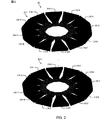
図2に、たとえば、14ギガヘルツ(GHz)において動作する複数の12ビームアレイ202(202−1、...、202−N)を有する航空機アンテナアレイシステム200の一例を示す。代表として、航空機アンテナアレイ202−1は、各々が、方位角において30°セクタをカバーし、約2.0インチ×0.45のインチの開口サイズをもち、>10dBi(dB等方性)の利得を有する、12個のホーンアンテナ210(210−1、...、210−12)を有する。一態様では、アンテナアレイの全径はほぼ8インチである。 FIG. 2 shows an example of an aircraft antenna array system 200 having a plurality of 12 beam arrays 202 (202-1,..., 202-N) operating at, for example, 14 gigahertz (GHz). Typically, the aircraft antenna array 202-1 each covers a 30 ° sector in azimuth, has an aperture size of approximately 2.0 inches by 0.45 inches, and> 10 dBi (dB isotropic). It has 12 horn antennas 210 (210-1, ..., 210-12) with gain. In one aspect, the overall diameter of the antenna array is approximately 8 inches.
図2は、12ビームアレイ構成における航空機アンテナアレイ202を示しているが、本開示および添付の特許請求の範囲の範囲内のまま他の構成が可能であることを認識されたい。具体的には、1つの例示的な構成は、4ビームアレイ構成における4アンテナアレイ202を含む。一態様では、複数の航空機アンテナアレイ202は、異なる仰角における地上基地局探索を可能にする。一態様では、複数のアンテナアレイ202は、仰角における地上基地局アンテナ探索のセクタ化を可能にする。この態様では、各要素はそれ自体のトランシーバに結合される。以下でさらに詳細に説明するように、地上基地局探索は、図1に示したように、航空機トランシーバ120と、地上基地局110などの次の地上基地局との間のハンドオフを可能にする。
Although FIG. 2 shows an
一態様では、航空機アンテナアレイシステム200は胴体の下に取り付けられ、航空機インターネットサービスを改善するために、補助アンテナが航空機の別個の部分に取り付けられる。特に、フライト中の航空機のバンキングまたはローリングは、胴体の下に取り付けられた航空機アンテナアレイシステム200と地上基地局102との間の通信を中断し得る。一態様では、補助アンテナは、航空機がバンクまたはロールする間、地上基地局との通信を扱うことによって、これらのときの航空機トランシーバ120と地上基地局102との間の通信の途絶を低減する。航空機アンテナ200の特性を図3Aおよび図3Bにさらに示す。
In one aspect, the aircraft antenna array system 200 is mounted below the fuselage, and auxiliary antennas are mounted on separate parts of the aircraft to improve aircraft Internet service. In particular, in-flight aircraft banking or rolling may interrupt communication between the aircraft antenna array system 200 mounted below the fuselage and the
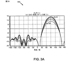
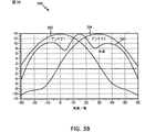
図3Aは、本開示の一態様による、0、5、10、15および20度の方位角における単一のアンテナ素子210のシミュレートされた仰角利得パターンの図300を示している。代表として、図3Aのx軸は、地平線が90°にある球面座標におけるθ角を表す。シミュレーションは無限グランドプレーン上で実行されるので、地平線の上方(−90と90との間)の利得パターンはイメージ理論により複製され、無視されるべきである。図3Bは、本開示の一態様による、2つの隣接する要素のシミュレートされた方位角利得パターン352および354とデジタル合成ビーム360との図350を示している。
FIG. 3A shows a diagram 300 of a simulated elevation gain pattern of a single antenna element 210 at azimuth angles of 0, 5, 10, 15, and 20 degrees, according to one aspect of the present disclosure. As a representative, the x-axis in FIG. 3A represents the θ angle in spherical coordinates with the horizon at 90 °. Since the simulation is performed on an infinite ground plane, the gain pattern above the horizon (between -90 and 90) is replicated by image theory and should be ignored. FIG. 3B illustrates a diagram 350 of two adjacent element simulated
航空機インターネットサービスを与えるための航空機アンテナ200の動作は、図1に示したように、現在の地上基地局102と次の地上基地局110との間での検出と航空機モデムハンドオフとを伴う。通信および探索の様々な方式がアンテナシステムによって採用され得る。一態様では、単一の受信チェーンが通信のために使用され、探索は連続的時間分割方法で実行される。別の態様では、一方のチェーンは地上局通信用であり、他方のチェーンは地上基地局探索用である、2つの受信チェーンが使用され得る。2受信チェーン構成では、探索チェーンはまた、探索していない間、利得およびスループットを増加させるためのダイバーシティ合成のために使用され得る。地上基地局探索は、以下のように実行され得る。
Operation of aircraft antenna 200 to provide aircraft Internet service involves detection and aircraft modem handoff between the current
一態様では、地上基地局探索は、所与の航空機アンテナ素子上で地上基地局から受信したすべてのパイロット信号の探索を含み得る。受信したパイロット信号は、航空機モデムがより強いパイロット信号をそれから受信している別の地上基地局に航空機モデムがハンドオフすべきか否かを判断するためにランク付けされる。あるアンテナ素子上での探索が完了すると、探索は別の要素に切り替わり、その要素上でのパイロット探索を繰り返し得る。一態様では、アンテナ素子210−2〜210−12の各々は、図2に示したように、アンテナ素子210−1によってデータが受信される間、地上局を継続的に探索し得る。 In one aspect, the ground base station search may include a search for all pilot signals received from the ground base station on a given aircraft antenna element. The received pilot signals are ranked to determine whether the aircraft modem should hand off to another ground base station from which the aircraft modem is receiving a stronger pilot signal. When the search on an antenna element is complete, the search switches to another element and the pilot search on that element can be repeated. In one aspect, each of the antenna elements 210-2 to 210-12 may continuously search for ground stations while data is received by the antenna element 210-1, as shown in FIG.
上記で説明した構成では、スイッチトアンテナ方式は、低い複雑さを維持しながら高い利得を達成するために、異なるアンテナ素子間で切り替えるトランシーバを必要とする。代替的に、フェーズドアレイ技法を使用して複数のアンテナ素子を合成することによって指向性ビームが形成され得る。一態様では、上記で説明したスイッチトアンテナ方式は、ダイバーシティを与えるためのハードウェア複雑さをわずかしか増加させずに、アンテナ利得をさらに増加させるために、2つの隣接するビーム352および354を合成して、合成ビーム360を形成し得る。一態様では、スイッチトアンテナ方式は、隣接するアンテナ素子の部分フェーズドアレイビーム合成を使用し得る。たとえば、隣接するビームの境界にまたはその近くに通信地上基地局があるとき、システム性能を改善するために隣接するビームが合成され得る。
In the configuration described above, the switched antenna scheme requires a transceiver that switches between different antenna elements in order to achieve high gain while maintaining low complexity. Alternatively, a directional beam can be formed by combining multiple antenna elements using phased array techniques. In one aspect, the switched antenna scheme described above combines two
図4に、地上基地局102と航空機トランシーバ120との設計のブロック図を示す。地上基地局102はアンテナ434a〜434tを装備し得、航空機トランシーバ120はアンテナ452a〜452rを装備し得る。
FIG. 4 shows a block diagram of a design of
地上基地局102において、送信プロセッサ420は、データソース412からデータを受信し、コントローラ/プロセッサ440から制御情報を受信し得る。プロセッサ420は、データと制御情報とを処理(たとえば、符号化およびシンボルマッピング)して、それぞれデータシンボルと制御シンボルとを取得し得る。プロセッサ420はまた基準シンボルを生成し得る。送信(TX)多入力多出力(MIMO)プロセッサ430は、適用可能な場合、データシンボル、制御シンボル、および/または基準シンボルに対して空間処理(たとえば、プリコーディング)を実行し得、出力シンボルストリームを変調器(MOD)432a〜432tに与え得る。各変調器432は、(たとえば、OFDMなどの)それぞれの出力シンボルストリームを処理して、出力サンプルストリームを取得し得る。各変調器432は、さらに、出力サンプルストリームを処理(たとえば、アナログへの変換、増幅、フィルタ処理、およびアップコンバート)して、ダウンリンク/順方向リンク信号を取得し得る。変調器432a〜432tからのダウンリンク信号は、それぞれアンテナ434a〜434tを介して送信され得る。
At the
航空機トランシーバ120において、アンテナ452a〜452rは、地上基地局102からダウンリンク/順方向リンク信号を受信し得、受信信号をそれぞれ復調器(DEMOD)454a〜454rに与え得る。各復調器454は、それぞれの受信信号を調整(たとえば、フィルタ処理、増幅、ダウンコンバート、およびデジタル化)して、入力サンプルを取得し得る。各復調器454は、さらに、(たとえば、OFDMなどの)入力サンプルを処理して、受信シンボルを取得し得る。MIMO検出器456は、すべての復調器454a〜454rから受信シンボルを取得し、適用可能な場合は受信シンボルに対してMIMO検出を実行し、検出されたシンボルを与え得る。受信プロセッサ458は、検出されたシンボルを処理(たとえば、復調、デインターリーブ、および復号)し、航空機トランシーバ120の復号されたデータをデータシンク460に与え、復号された制御情報をコントローラ/プロセッサ480に与え得る。
In
逆方向リンク/アップリンク上では、航空機トランシーバ120において、送信プロセッサ464は、データソース462からデータを受信し処理し、コントローラ/プロセッサ480から制御情報を受信し処理し得る。プロセッサ464はまた、基準信号のための基準シンボルを生成し得る。送信プロセッサ464からのシンボルは、適用可能な場合はTX MIMOプロセッサ466によってプリコードされ、さらに変調器454a〜454rによって処理され、地上基地局102に送信され得る。地上基地局102において、航空機トランシーバ120からのアップリンク/逆方向リンク信号は、アンテナ434によって受信され、復調器432によって処理され、適用可能な場合はMIMO検出器436によって検出され、さらに受信プロセッサ438によって処理されて、航空機トランシーバ120によって送られた復号されたデータおよび制御情報が取得され得る。プロセッサ438は、復号されたデータをデータシンク439に与え、復号された制御情報をコントローラ/プロセッサ440に与え得る。
On the reverse link / uplink, at
コントローラ/プロセッサ440および480は、それぞれ地上基地局102および航空機トランシーバ120における動作を指示し得る。地上基地局102におけるプロセッサ440および/または他のプロセッサならびにモジュールは、本明細書で説明する技法についての様々なプロセスを実行するかまたはその実行を指示し得る。航空機トランシーバ120におけるプロセッサ480および/または他のプロセッサならびにモジュールはまた、図8の使用方法フローチャートに示す機能ブロック、および/または本明細書で説明する技法のための他のプロセスを実行するかまたはその実行を指示し得る。メモリ442および482は、それぞれ地上基地局102および航空機トランシーバ120のためのデータおよびプログラムコードを記憶し得る。
Controllers /
本開示の態様による、航空機アンテナ200と通信するためのアンテナアレイを含む地上局アンテナアレイシステムを図5および図6に示す。一態様では、地上局アンテナアレイシステムは、たとえば、図5および図6に示すように、複数の航空機と同時に通信することが可能な高利得マルチビームアンテナアレイを含み得る。図5および図6は、本開示の態様によるセクタ化およびアンテナアレイ構成の2つの例を示している。 A ground station antenna array system including an antenna array for communicating with an aircraft antenna 200 in accordance with aspects of the present disclosure is shown in FIGS. In one aspect, a ground station antenna array system may include a high gain multi-beam antenna array capable of communicating simultaneously with multiple aircraft, for example, as shown in FIGS. 5 and 6 illustrate two examples of sectorization and antenna array configurations in accordance with aspects of the present disclosure.
一態様では、セクタ化は、たとえば、図5および図6に示すように、システムスループットを増加させるために仰角においてセクタを分割することを含み得る。代表として、方位角および仰角におけるカバレージ領域は、アンテナアレイが、カバレージエリア中ですべての角度にわたってそれの利得要件を維持することができる狭い領域に分割され得る。一構成では、アンテナは14GHz範囲内で動作させられ得、カバレージ領域は、方位角において120°であり、仰角において0.5°〜10°である。地上基地局アンテナ利得は、仰角0.5°では40dBiであり得、航空機に対するより低い経路損失により、仰角10°では25.5dBiまで低減される。 In one aspect, sectoring may include dividing the sector at elevation to increase system throughput, for example, as shown in FIGS. Typically, the coverage area in azimuth and elevation can be divided into narrow areas where the antenna array can maintain its gain requirements across all angles in the coverage area. In one configuration, the antenna can be operated in the 14 GHz range, and the coverage area is 120 ° in azimuth and 0.5 ° to 10 ° in elevation. The ground base station antenna gain may be 40 dBi at an elevation angle of 0.5 ° and is reduced to 25.5 dBi at an elevation angle of 10 ° due to lower path loss to the aircraft.
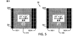
再び図5を参照すると、図5は、各々が方位角において60°をカバーする2つのアンテナパネル510および530をもつ地上基地局アンテナアレイシステム500の構成を示している。一態様では、各アンテナパネル510/530は、それぞれ、本明細書では地上局アンテナアレイと呼ぶことがある、アンテナ素子522(522−1、...、522−N)、524(524−1、...、524−N)、542(542−1、...、542−N)、および544(544−1、...、544−N)のN×Mアレイ520/540から構成され得る。一態様では、各アンテナ素子は送信/受信(T/R)モジュールを含む。代表として、地上局アンテナアレイ520および540は50×6個のアンテナ素子を含むが、説明する態様および添付の特許請求の範囲の範囲内のまま他の構成が可能である。一態様では、信号を合成し、望まれる総合利得を達成するために、デジタルビーム形成が採用され得る。デジタルビーム形成は、各パネルの異なる列および行中のアンテナ素子にわたって計算され得る。
Referring again to FIG. 5, FIG. 5 shows the configuration of a terrestrial base station
図6は、仰角をカバーするアンテナパネル610、620、630、および640/650、660、670、および680の数が4まで増加され、方位角をカバーするパネル602および604の数が2に維持された、地上局アンテナアレイシステム600の構成を示している。一態様では、より高い仰角においてより低い利得が必要とされるので、より高い仰角をカバーするパネル(610/650)の開口サイズは、低い仰角をカバーするパネル(640/680)の開口サイズよりも小さい。各アンテナアレイ612(612−1、...、612−N)/650(650−1、...、650−N)は、デジタルビーム形成が適用される50×1個の要素を含み得る。一態様では、デジタルビームの生成は、たとえば、航空機の仰角に応じて、隣接するパネル610/650と次の隣接するパネル620/660との間で切り替えられる。
FIG. 6 shows that the number of
デジタルビーム形成のためにより少ない数の要素を利用する他の構成は、方位角において各パネルのカバレージ領域をさらに低減することと、アレイサイズを維持したまま要素のアンテナ開口を増加させることとによって達成され得る。これにより、全体的な地上局アンテナアレイサイズはより大きくなるが、デジタル信号処理はあまり複雑でなくなり得る。一態様では、上記の例では100×4個のアンテナに対応する単一の要素が、デジタルビーム形成なしに各セクタのために使用され得る。 Other configurations utilizing a smaller number of elements for digital beamforming are achieved by further reducing the coverage area of each panel in azimuth and increasing the antenna aperture of the elements while maintaining the array size. Can be done. This makes the overall ground station antenna array size larger, but digital signal processing can be less complex. In one aspect, a single element corresponding to 100 × 4 antennas in the above example may be used for each sector without digital beamforming.
一態様では、複数のステアラブルペンシルビームを与えるために各アレイにおいてデジタルビーム形成が使用され得る。アレイの各要素のための信号がT/R(送信/受信)モジュールを通して受け渡され得、ベースバンドに変換される。一態様では、指向性ビームの位相シフトがビームステアリングコンピュータによって計算され、各信号に適用される。同様の位相ファクタが送信信号に適用され、送信/受信モジュールを通してアンテナ素子中に受け渡される。一態様では、較正プロシージャが、各要素の振幅および位相を等化し、回路の時間変動をなくす。 In one aspect, digital beamforming can be used in each array to provide a plurality of steerable pencil beams. The signal for each element of the array can be passed through a T / R (transmit / receive) module and converted to baseband. In one aspect, the phase shift of the directional beam is calculated by a beam steering computer and applied to each signal. A similar phase factor is applied to the transmitted signal and passed through the transmit / receive module and into the antenna element. In one aspect, the calibration procedure equalizes the amplitude and phase of each element and eliminates time variation of the circuit.
上述のように、較正は、アンテナおよび送信/受信ユニットの異なる位相/振幅応答を補償する。較正の1つのタイプは、ビルトイン回路を使用して工場で実行され得る。この較正は、任意のよく知られている技法を使用し得る。ビルトイン較正方式はまた、温度およびエージングによる変化を追跡するために、現場で定期較正のために使用され得る。較正のための別の手法は、地上基地局と航空機モデムとの間の2方向通信を実行しながらリアルタイム較正を行うためにエアインターフェースに組み込まれ得る。一態様では、較正は、エアインターフェースの通信シグナリングを使用して定期的に実行される。特に、オーバージエア(OTA)リアルタイム較正は、空対地2方向通信システムが動作している間に実行され得る。 As mentioned above, calibration compensates for the different phase / amplitude responses of the antenna and the transmit / receive unit. One type of calibration can be performed at the factory using built-in circuitry. This calibration may use any well-known technique. Built-in calibration schemes can also be used for periodic calibration in the field to track changes due to temperature and aging. Another approach for calibration can be incorporated into the air interface to perform real-time calibration while performing two-way communication between the ground base station and the aircraft modem. In one aspect, the calibration is performed periodically using air interface communication signaling. In particular, over-the-air (OTA) real-time calibration can be performed while an air-to-ground two-way communication system is operating.
一態様では、地上基地局(GBS)ユニット上の順方向リンク(FL)は、セクタ全体をカバーするワイドビーム上でパイロット信号を定期的に送信する。本明細書で説明するように、地上基地局の順方向リンク上で定期的に送信されたパイロット信号は、セクタワイドパイロット(SWP)と呼ばれることがある。一態様では、セクタワイドパイロットは、航空機が新しい地上基地局を検出することと、地上基地局に同期することと、以下で説明する定期較正プロシージャに関する情報などのシステムパラメータを受信することとを可能にし得る。たとえば、図1に示したように、地上基地局102は、順方向リンク108上でセクタワイドパイロットを送信し得る。
In one aspect, the forward link (FL) on a ground base station (GBS) unit periodically transmits pilot signals on a wide beam that covers the entire sector. As described herein, pilot signals that are periodically transmitted on the forward link of a terrestrial base station may be referred to as sector wide pilots (SWP). In one aspect, the sector-wide pilot allows the aircraft to detect a new ground base station, synchronize to the ground base station, and receive system parameters such as information regarding the periodic calibration procedure described below. Can be. For example, as shown in FIG. 1,
一態様では、セクタワイドパイロットを送信するために使用されるワイドビームは、たとえば、図5および図6に示した個々の地上局アンテナアレイ要素(522、524、542、544、612、または650)のいずれかの上で送信することによって形成され得る。航空機モデムは、それの探索プロシージャの一部としてこのセクタワイドパイロットを検出し得る。地上局アンテナアレイ要素の送信要素を較正するための1つの可能なリアルタイムプロシージャは、以下のように実行される。 In one aspect, the wide beam used to transmit the sector wide pilots may be, for example, the individual ground station antenna array elements (522, 524, 542, 544, 612, or 650) illustrated in FIGS. Can be formed by transmitting on any of the above. The aircraft modem may detect this sector wide pilot as part of its search procedure. One possible real-time procedure for calibrating the transmit elements of the ground station antenna array element is performed as follows.
一態様では、地上基地局は定期的に較正モードに入る。較正モードの時間は、セクタワイドパイロットを搬送する同じワイドビーム上において順方向リンク上で送られ得る。地上局アンテナアレイの送信側を較正することが最初に実行され得る。特に、地上基地局送信機は、較正に割り当てられた時間期間中に、すべての地上局アンテナアレイ要素上のセクタワイドパイロットを連続的に送り得る。復調の後に、k番目の地上局アンテナアレイ要素から航空機において受信された信号は、次式によって与えられる。
![]()
![]()
式(1)において、第1の項は、RFチェーンにおける利得(αk)および遅延(θk)に対応し得る。第2の項は、アンテナ素子間の結合の振幅(βk)および位相(φk)に対応し得る。第3の項は、アンテナアレイ間隔からの位相(νk)に対応し得る。最後の項は、マルチパスフェージング振幅(σk)および位相(∂k)に対応し得る。また、式(1)のjは、複素数の虚数部を表す。 In equation (1), the first term may correspond to gain (α k ) and delay (θ k ) in the RF chain. The second term may correspond to the amplitude (β k ) and phase (φ k ) of the coupling between the antenna elements. The third term may correspond to the phase (ν k ) from the antenna array spacing. The last term may correspond to multipath fading amplitude (σ k ) and phase (∂ k ). Moreover, j of Formula (1) represents the imaginary part of a complex number.
一態様では、最初の3つの項はハードウェアに起因し、いくつかの時間測定を行い、最後の項を平均化することによって推定され得る。たとえば、航空機が進む高い速度を仮定すれば、チャネル変更は極めて迅速に(たとえば、ミリ秒程度で)行われる。一態様では、式(1)のいくつかの測定は、2ミリ秒間隔にわたって行われ得る。これらの個別の測定値は、次いで、マルチパスに起因する式(1)の最後の項を平均化するためにフィルタ処理され得る。式(1)において、最後の項は、チャネルが周波数非選択性であること、またはOFDM(直交周波数分割多重化)物理レイヤの個々のトーン上でなど、ナローバンド幅上で測定が行われることのいずれかを仮定し得る。 In one aspect, the first three terms are due to hardware and can be estimated by taking several time measurements and averaging the last term. For example, assuming a high speed at which the aircraft travels, channel changes occur very quickly (eg, in the order of milliseconds). In one aspect, some measurements of equation (1) may be made over a 2 millisecond interval. These individual measurements can then be filtered to average the last term of equation (1) due to multipath. In equation (1), the last term indicates that the channel is frequency non-selective or that measurements are made on the narrow bandwidth, such as on individual tones of the OFDM (Orthogonal Frequency Division Multiplexing) physical layer. Either can be assumed.
ワイドバンド幅システムのための一態様では、すべての周波数にわたってハードウェアの較正を保証するために、十分な数のトーン上で信号が送られ得る。航空機モデムは、上記で説明したように較正係数を計算し得、係数を地上基地局に送信し、したがって、地上基地局は、たとえば、図1に示したように、航空機に向かう順方向リンクビーム形成のためにこれらの係数を使用し得る。 In one aspect for a wide bandwidth system, the signal may be sent on a sufficient number of tones to ensure hardware calibration across all frequencies. The aircraft modem may calculate the calibration factor as described above and transmit the factor to the ground base station so that the ground base station may forward link beam toward the aircraft, eg, as shown in FIG. These factors can be used for formation.
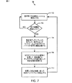
空対地2方向通信システムのリアルタイム較正のためのプロセスは、以下のように実行され得る。図7は、本開示の一態様による、地上局アンテナアレイシステムを含む空対地2方向通信システムのリアルタイム較正のための方法700を示すフローチャートである。プロセスブロック702において、空対地2方向通信システムは、たとえば、図1に示したように、航空機にインターネットサービスを与えるように動作する。プロセスブロック704において、空対地2方向通信システムの動作中に較正期間が検出されたかどうかを判断する。較正期間が検出されるまで、空対地2方向通信システムの動作は続く。較正期間が検出されると、基地局アンテナシステムの較正が以下のように実行され得る。
The process for real-time calibration of an air-to-ground two-way communication system can be performed as follows. FIG. 7 is a flowchart illustrating a method 700 for real-time calibration of an air-to-ground two-way communication system including a ground station antenna array system according to one aspect of the present disclosure. In
プロセスブロック706において、基地局アンテナアレイの各アンテナ素子によってワイドビーム上でセクタワイドパイロット信号を連続送信する。一態様では、アンテナ500(図5)は、地上局アンテナアレイ520および540の各要素上でセクタワイドパイロット(SWP)を送信し得る。図6に示した構成では、地上局アンテナシステム600は、航空機の仰角に応じて、隣接するアンテナパネル610および650、620および660、630および670、または640および680のうちの1つの上でセクタワイドパイロットを送信し得る。
In
再び図7を参照すると、プロセスブロック708において、較正期間中にセクタワイドパイロット信号に応答して、航空機からアンテナアレイの順方向リンク較正係数を受信する。一態様では、較正係数は、航空機によって受信されたセクタワイドパイロット信号を特徴づける。プロセスブロック710において、本開示の一態様によれば、たとえば、式(1)を使用して、受信した較正係数に従って地上局アンテナアレイシステムのアンテナアレイのリアルタイム較正を実行する。
Referring again to FIG. 7, at
一態様では、受信側較正は、上記の方式と同様に実行され得るが、図1に示したように、航空機モデムに逆方向リンク(RL)106上でパイロットシーケンスを送信させることによって実行され得る。パイロット信号は、地上基地局のアンテナ素子の各々での検出を可能にするために、十分な量のエネルギーおよび十分な量の継続時間を用いて送られ得る。送信チェーンを較正するための上記で説明した方式と同様に、一態様では、受信チェーンの位相および振幅は、マルチパスフェージングによる変動を平均化することによって推定され得る。 In one aspect, receiver calibration may be performed in a manner similar to that described above, but may be performed by having the aircraft modem transmit a pilot sequence on the reverse link (RL) 106, as shown in FIG. . The pilot signal may be sent with a sufficient amount of energy and a sufficient amount of duration to allow detection at each of the ground base station antenna elements. Similar to the scheme described above for calibrating the transmit chain, in one aspect, the phase and amplitude of the receive chain can be estimated by averaging the variations due to multipath fading.
地上基地局および航空機アンテナが較正された後、ビーム形成が多くの方法で実行され得る。一態様では、航空機は、たとえば、全地球測位システム(GPS)などの位置ロケーションシステムを用いて判断され得る現在の位置ロケーションに基づいて、それの位置を地上基地局に送る。地上基地局は、この情報を使用して、航空機の方向に、また地上基地局の受信側でビームを形成し得る。較正アンテナシステムでは、航空機および地上基地局の位置の知識は、航空機のロケーションのほうへビームのボアサイト(bore sight)を向けるためのフェーズドアレイアンテナ係数を計算するために使用され得る。フライト中に、本開示の一態様によれば、地上基地局に定期的に報告される航空機の位置を使用してビームが調整され得る。 After the ground base station and aircraft antenna are calibrated, beamforming can be performed in a number of ways. In one aspect, the aircraft sends its position to the ground base station based on a current position location that can be determined using a position location system, such as, for example, a global positioning system (GPS). The ground base station may use this information to form a beam in the direction of the aircraft and at the receiving side of the ground base station. In a calibration antenna system, knowledge of the position of the aircraft and ground base station can be used to calculate phased array antenna coefficients for directing the beam bore sight towards the location of the aircraft. During a flight, according to one aspect of the present disclosure, the beam position may be adjusted using aircraft positions that are periodically reported to ground base stations.
一態様では、航空機および地上基地局は、航空機および地上基地局において受信される信号対雑音干渉比(SINR)を増加させるかまたは最大にするようにそれらのビームを調整し得る。たとえば、地上基地局は、それの送信ビームをわずかに移動し得る。航空機は、航空機において受信されたSINR測定値を地上基地局に報告する。一態様では、地上基地局は、航空機から受信したSINRフィードバックに基づいて、それのビームを調整することによって、改善されたまたは最適な送信ビームを見つけ得る。一態様では、地上基地局は、たとえば、測定された信号エネルギーに基づいて、隣接するビームのうちの1つが改善された性能を与えるかどうかを判断するために、1つまたは複数の隣接するビームを送り得る。一態様では、改善されたまたは最適なビームの検出は、航空機から地上基地局への逆方向リンク上で使用され得る。 In one aspect, aircraft and ground base stations may adjust their beams to increase or maximize the signal to noise interference ratio (SINR) received at the aircraft and ground base stations. For example, a ground base station may move its transmit beam slightly. The aircraft reports the SINR measurements received at the aircraft to the ground base station. In one aspect, the terrestrial base station may find an improved or optimal transmit beam by adjusting its beam based on SINR feedback received from the aircraft. In one aspect, the terrestrial base station can determine one or more adjacent beams, for example, to determine whether one of the adjacent beams provides improved performance based on the measured signal energy. Can send. In one aspect, improved or optimal beam detection may be used on the reverse link from the aircraft to the ground base station.
順方向リンクと逆方向リンクとが相反するTDD(時分割複信)チャネルでは、較正されたハードウェア位相および遅延を除いて、地上基地局は、隣接するビーム上で受信されたSINRを比較することによって所望または最良の受信ビームを判断し得る。次いで、地上基地局は、それの受信側での所望のまたは最適なビームに基づいて、航空機に向かうビームを形成し得る。一態様では、地上基地局は、所望のまたは最適な受信ビームを繰り返し判断し、それに応じて送信ビームを調整する。マルチビーム切替え可能アレイアンテナを装備した航空機による空対地通信のためのプロセスは、以下のように実行され得る。 For TDD (Time Division Duplex) channels where the forward and reverse links are conflicting, the terrestrial base station compares the SINR received on adjacent beams, except for calibrated hardware phase and delay. Thereby determining the desired or best receive beam. The ground base station may then form a beam towards the aircraft based on the desired or optimal beam at its receiver. In one aspect, the terrestrial base station repeatedly determines the desired or optimal receive beam and adjusts the transmit beam accordingly. The process for air-to-ground communication with an aircraft equipped with a multi-beam switchable array antenna may be performed as follows.
図8は、本開示の一態様による、マルチビーム切替え可能アンテナ素子の複数のアンテナアレイを装備した航空機による空対地通信のための方法800を示すフローチャートである。プロセスブロック802において、アンテナの第1のアンテナ素子によってネットワークの第1の地上基地局からワイドビーム上の第1のパイロット信号を受信する。一態様では、アンテナ200(図2)は、航空機からの方位角の第1の範囲をカバーする第1のアンテナ素子210(210−1、...、210−12)上でセクタワイドパイロット(SWP)を受信し得る。図2に示した構成では、航空機アンテナ200は、各々が方位角において30°セクタをカバーする12個のホーンアンテナ210(210−1、...、210−12)を有する。
FIG. 8 is a flowchart illustrating a
再び図8を参照すると、プロセスブロック804において、第1のアンテナ素子(たとえば210−1)によって第1の地上局から指向ビーム上のデータを受信する。プロセスブロック806において、方位角の第1の範囲とは異なる航空機からの方位角の第2の範囲をカバーするアンテナの第2のアンテナ素子によって、ネットワークの少なくとも1つの第2の地上基地局からワイドビーム上の少なくとも1つの第2のパイロット信号を受信する。たとえば、図1に示したように、第1の地上基地局102からデータが受信されている間に、第2の地上局110からセクタワイドパイロットが受信され得る。
Referring again to FIG. 8, at
図2に示したように、第2のアンテナ素子210−2によってセクタワイドパイロットが受信される間に、第1のアンテナ素子210−1によってデータが受信され得る。一構成では、アンテナ素子210−2〜210−12の各々は、アンテナ素子210−1によってデータが受信される間、地上局を継続的に探索し得る。代替態様では、時分割モードが、データを受信するために単一のアンテナ素子を使用することによって動作し、データが受信されていないとき、残りのアンテナ素子は、航空機モデムハンドオフを実行すべきかどうかを判断するために地上局を探索し得る。 As shown in FIG. 2, data may be received by the first antenna element 210-1 while a sector-wide pilot is received by the second antenna element 210-2. In one configuration, each of antenna elements 210-2 to 210-12 may continuously search for ground stations while data is received by antenna element 210-1. In an alternative aspect, time division mode operates by using a single antenna element to receive data, and when no data is received, the remaining antenna elements should perform an aircraft modem handoff May be searched for ground stations to determine
再び図8を参照すると、プロセスブロック808において、(1つまたは複数の)第2のパイロット信号の信号強度を第1のパイロット信号の信号強度と比較する。プロセスブロック810において、第2のアンテナ素子によって受信された第2のパイロット信号強度が、第1のアンテナ素子上で受信された第1のパイロット信号強度よりも大きいと判断したことに応答して、第1のアンテナ素子から第2のアンテナ素子にデータの受信を切り替える。一態様では、方法800は、図8に示すように、複数の航空機アンテナアレイを有する構成のための各航空機アンテナアレイ202(図2)について繰り返される。代替態様では、方法800は、選択された航空機アンテナアレイ(たとえば202−1)について実行される。
Referring again to FIG. 8, at
非静止衛星端末からの送信が、地上基地局から被サービス航空機上の航空機トランシーバへの通信に干渉し得る。また、他の航空機が、地上基地局から被サービス航空機上の航空機トランシーバへの通信に干渉し得る。さらに、KaバンドまたはKuバンドのいずれかが空対地通信システムによって使用されるとき、雨によって信号劣化が生じ得る。本開示の態様は、航空機端末に対するこのタイプの干渉と信号劣化とを緩和し得る。 Transmissions from non-geostationary satellite terminals can interfere with communications from ground base stations to aircraft transceivers on the served aircraft. Other aircraft may also interfere with communications from the ground base station to the aircraft transceiver on the served aircraft. Further, when either the Ka band or the Ku band is used by an air-to-ground communication system, signal degradation can occur due to rain. Aspects of the present disclosure may mitigate this type of interference and signal degradation for aircraft terminals.
図1に示したように、地上基地局102の順方向リンク108上の送信電力は、干渉を克服するために増加され、地上基地局110の順方向リンク送信電力の等しい減少を伴い得る。一態様では、地上基地局コントローラ/プロセッサ440(図4)は、様々な地上基地局にわたる全送信電力の和が一定のままになるように、様々な基地局の間で送信電力を調整することを担当する。
As shown in FIG. 1, the transmit power on the
特に、航空機受信機は、信号対干渉雑音比(SINR)を測定し、測定されたSINRのインデックスを地上基地局に送り得る。一態様では、地上基地局は、航空機において受信されたSINRをターゲット値より上に維持するように順方向リンクビーム上の送信電力を調整する。雨の場合、信号は減衰してくるので、航空機における受信されたSINRは低減する。各ビームは最大送信電力を与えられ得る。基地局コントローラは、すべての地上基地局からの全送信電力に対して限界を課する。航空機受信機への他のシステムからの干渉の場合、SINRの干渉項が増加し、航空機によって受信されるSINRを低減することになる。一態様では、地上基地局コントローラは、航空機モデムからのSINRフィードバックに応答して、順方向リンク電力を増加させ得る。 In particular, the aircraft receiver may measure a signal to interference noise ratio (SINR) and send an index of the measured SINR to the terrestrial base station. In one aspect, the terrestrial base station adjusts the transmit power on the forward link beam to maintain the SINR received at the aircraft above the target value. In the case of rain, the received signal at the aircraft is reduced because the signal is attenuated. Each beam may be given a maximum transmit power. The base station controller imposes a limit on the total transmit power from all terrestrial base stations. In the case of interference from other systems to the aircraft receiver, the SINR interference term will increase and reduce the SINR received by the aircraft. In one aspect, the terrestrial base station controller may increase forward link power in response to SINR feedback from the aircraft modem.
図9は、本開示の一態様による、航空機干渉を緩和するためにサービング地上基地局からの順方向リンク上の送信電力を増加させるための方法900を示すフローチャートである。プロセスブロック902において、サービング地上基地局から航空機への、地上基地局アンテナアレイの順方向リンク上でのデータの送信中に干渉を検出する。プロセスブロック904において、サービング地上基地局は、航空機干渉を緩和するために順方向リンク上の送信電力を増加させる。一態様では、サービング地上基地局の送信電力を増加させることは、1つまたは複数の他の地上基地局の送信電力の等しい減少を伴う。したがって、プロセスブロック906において、1つまたは複数の他の地上基地局の送信電力の減少を実行する。一態様では、様々な地上基地局にわたる全送信電力の和が一定のままになるように、送信電力の減少が実行される。
FIG. 9 is a flowchart illustrating a
一構成では、空対地2方向通信システムの動作中に通信シグナリングプロトコルの一部として航空機から受信した順方向リンク較正係数に従って地上基地局アンテナアレイを較正するための手段を含む、ワイヤレス通信のための地上基地局102が構成される。一態様では、較正手段は、図4のコントローラ/プロセッサ440、および/またはメモリ442であり得る。地上基地局はまた、ナロービームを介して地上基地局アンテナアレイと航空機との間で通信するための手段を含むように構成される。一態様では、通信手段は、図5および図6に示した地上基地局アンテナアレイ、ならびに/あるいは図4のアンテナ434a〜r、復調器434a〜r、送信プロセッサ420、コントローラ/プロセッサ440、および/またはメモリ442であり得る。別の態様では、上述の手段は、上述の手段によって具陳される機能を実行するように構成されたモジュールまたは任意の装置であり得る。
In one configuration, for wireless communication, including means for calibrating a terrestrial base station antenna array according to a forward link calibration factor received from an aircraft as part of a communication signaling protocol during operation of an air-to-ground two-way communication system. A
さらに、本明細書の開示に関して説明した様々な例示的な論理ブロック、モジュール、回路、およびアルゴリズムステップは、電子ハードウェア、コンピュータソフトウェア、または両方の組合せとして実装され得ることを、当業者は諒解されよう。ハードウェアとソフトウェアのこの互換性を明確に示すために、様々な例示的な構成要素、ブロック、モジュール、回路、およびステップについて、上記では概してそれらの機能に関して説明した。そのような機能をハードウェアとして実装するか、ソフトウェアとして実装するかは、特定の適用例および全体的なシステムに課された設計制約に依存する。当業者は、説明した機能を特定の適用例ごとに様々な方法で実装し得るが、そのような実装の決定は、本開示の範囲からの逸脱を生じるものと解釈すべきではない。 Moreover, those skilled in the art will appreciate that the various exemplary logic blocks, modules, circuits, and algorithm steps described in connection with the disclosure herein can be implemented as electronic hardware, computer software, or a combination of both. Like. To clearly illustrate this interchangeability of hardware and software, various illustrative components, blocks, modules, circuits, and steps have been described above generally in terms of their functionality. Whether such functionality is implemented as hardware or software depends upon the particular application and design constraints imposed on the overall system. Those skilled in the art may implement the described functionality in a variety of ways for each particular application, but such implementation decisions should not be construed as departing from the scope of the present disclosure.
本明細書の開示に関して説明した様々な例示的な論理ブロック、モジュール、および回路は、汎用プロセッサ、デジタル信号プロセッサ(DSP)、特定用途向け集積回路(ASIC)、フィールドプログラマブルゲートアレイ(FPGA)または他のプログラマブル論理デバイス、個別ゲートまたはトランジスタ論理、個別ハードウェア構成要素、あるいは本明細書で説明した機能を実行するように設計されたそれらの任意の組合せを用いて実装または実行され得る。汎用プロセッサはマイクロプロセッサであり得るが、代替として、プロセッサは、任意の従来のプロセッサ、コントローラ、マイクロコントローラ、または状態機械であり得る。プロセッサはまた、コンピューティングデバイスの組合せ、たとえば、DSPとマイクロプロセッサとの組合せ、複数のマイクロプロセッサ、DSPコアと連携する1つまたは複数のマイクロプロセッサ、または任意の他のそのような構成として実装され得る。 Various exemplary logic blocks, modules, and circuits described in connection with the disclosure herein may be general purpose processors, digital signal processors (DSPs), application specific integrated circuits (ASICs), field programmable gate arrays (FPGAs), or others. Programmable logic device, individual gate or transistor logic, individual hardware components, or any combination thereof designed to perform the functions described herein. A general purpose processor may be a microprocessor, but in the alternative, the processor may be any conventional processor, controller, microcontroller, or state machine. The processor is also implemented as a combination of computing devices, eg, a DSP and microprocessor combination, a plurality of microprocessors, one or more microprocessors associated with a DSP core, or any other such configuration. obtain.
本明細書の開示に関して説明した方法またはアルゴリズムのステップは、直接ハードウェアで実施されるか、プロセッサによって実行されるソフトウェアモジュールで実施されるか、またはその2つの組合せで実施され得る。ソフトウェアモジュールは、RAMメモリ、フラッシュメモリ、ROMメモリ、EPROMメモリ、EEPROMメモリ、レジスタ、ハードディスク、リムーバブルディスク、CD−ROM、または当技術分野で知られている任意の他の形態の記憶媒体中に常駐し得る。例示的な記憶媒体は、プロセッサが記憶媒体から情報を読み取り、記憶媒体に情報を書き込むことができるように、プロセッサに結合される。代替として、記憶媒体はプロセッサに一体化され得る。プロセッサおよび記憶媒体はASIC中に常駐し得る。ASICはユーザ端末中に常駐し得る。代替として、プロセッサおよび記憶媒体は、ユーザ端末中に個別構成要素として常駐し得る。 The method or algorithm steps described in connection with the disclosure herein may be implemented directly in hardware, implemented in software modules executed by a processor, or a combination of the two. A software module resides in RAM memory, flash memory, ROM memory, EPROM memory, EEPROM memory, registers, hard disk, removable disk, CD-ROM, or any other form of storage medium known in the art. Can do. An exemplary storage medium is coupled to the processor such that the processor can read information from, and write information to, the storage medium. In the alternative, the storage medium may be integral to the processor. The processor and the storage medium can reside in an ASIC. The ASIC may reside in the user terminal. In the alternative, the processor and the storage medium may reside as discrete components in a user terminal.
1つまたは複数の例示的な設計では、説明した機能は、ハードウェア、ソフトウェア、ファームウェア、またはそれらの組合せで実装され得る。ソフトウェアで実装した場合、機能は、1つまたは複数の命令またはコードとしてコンピュータ可読媒体上に記憶されるか、あるいはコンピュータ可読媒体を介して送信され得る。コンピュータ可読媒体は、ある場所から別の場所へのコンピュータプログラムの転送を可能にする任意の媒体を含む、コンピュータ記憶媒体とコンピュータ通信媒体の両方を含む。記憶媒体は、汎用または専用コンピュータによってアクセスされ得る任意の利用可能な媒体であり得る。限定ではなく例として、そのようなコンピュータ可読媒体は、RAM、ROM、EEPROM、CD−ROMまたは他の光ディスクストレージ、磁気ディスクストレージまたは他の磁気ストレージデバイス、あるいは命令またはデータ構造の形態の所望のプログラムコード手段を搬送または記憶するために使用され得、汎用もしくは専用コンピュータ、または汎用もしくは専用プロセッサによってアクセスされ得る、任意の他の媒体を備えることができる。また、いかなる接続もコンピュータ可読媒体と適切に呼ばれる。たとえば、ソフトウェアが、同軸ケーブル、光ファイバーケーブル、ツイストペア、デジタル加入者回線(DSL)、または赤外線、無線、およびマイクロ波などのワイヤレス技術を使用して、ウェブサイト、サーバ、または他のリモートソースから送信される場合、同軸ケーブル、光ファイバーケーブル、ツイストペア、DSL、または赤外線、無線、およびマイクロ波などのワイヤレス技術は、媒体の定義に含まれる。本明細書で使用するディスク(disk)およびディスク(disc)は、コンパクトディスク(disc)(CD)、レーザーディスク(登録商標)(disc)、光ディスク(disc)、デジタル多用途ディスク(disc)(DVD)、フロッピー(登録商標)ディスク(disk)およびブルーレイ(登録商標)ディスク(disc)を含み、ディスク(disk)は、通常、データを磁気的に再生し、ディスク(disc)は、データをレーザーで光学的に再生する。上記の組合せもコンピュータ可読媒体の範囲内に含めるべきである。 In one or more exemplary designs, the functions described may be implemented in hardware, software, firmware, or combinations thereof. If implemented in software, the functions may be stored on or transmitted over as one or more instructions or code on a computer-readable medium. Computer-readable media includes both computer storage media and computer communication media including any medium that facilitates transfer of a computer program from one place to another. A storage media may be any available media that can be accessed by a general purpose or special purpose computer. By way of example, and not limitation, such computer readable media can be RAM, ROM, EEPROM, CD-ROM or other optical disk storage, magnetic disk storage or other magnetic storage device, or desired program in the form of instructions or data structures. Any other medium that can be used to carry or store the code means and that can be accessed by a general purpose or special purpose computer, or a general purpose or special purpose processor can be provided. Any connection is also properly termed a computer-readable medium. For example, software sends from a website, server, or other remote source using coaxial cable, fiber optic cable, twisted pair, digital subscriber line (DSL), or wireless technologies such as infrared, wireless, and microwave Where included, coaxial technology, fiber optic cable, twisted pair, DSL, or wireless technologies such as infrared, radio, and microwave are included in the definition of media. As used herein, a disk and a disc are a compact disc (CD), a laser disc (registered trademark) (disc), an optical disc (disc), a digital versatile disc (DVD). ), Floppy® disk and Blu-ray® disk, which normally reproduces the data magnetically, and the disk uses a laser to reproduce the data. Reproduce optically. Combinations of the above should also be included within the scope of computer-readable media.
本開示についての以上の説明は、いかなる当業者も本開示を作成または使用することができるように与えたものである。本開示への様々な修正は当業者には容易に明らかとなり、本明細書で定義した一般原理は、本開示の趣旨または範囲から逸脱することなく他の変形形態に適用され得る。したがって、本開示は、本明細書で説明した例および設計に限定されるものではなく、本明細書で開示した原理および新規の特徴に合致する最も広い範囲を与えられるべきである。 The previous description of the disclosure is provided to enable any person skilled in the art to make or use the disclosure. Various modifications to this disclosure will be readily apparent to those skilled in the art, and the generic principles defined herein may be applied to other variations without departing from the spirit or scope of this disclosure. Accordingly, the present disclosure is not limited to the examples and designs described herein but is to be accorded the widest scope consistent with the principles and novel features disclosed herein.
Claims (20)
前記空対地2方向通信システムの動作中に通信シグナリングプロトコルの一部として航空機から受信した順方向リンク較正係数に従って地上基地局アンテナアレイを較正すること、
を備える。 A method for real-time calibration of an air-to-ground two-way communication system comprising:
Calibrating a terrestrial base station antenna array according to a forward link calibration factor received from an aircraft as part of a communication signaling protocol during operation of the air-to-ground two-way communication system;
Is provided.
少なくとも1つの較正期間中に前記地上基地局アンテナアレイの複数のアンテナ素子の各々によってワイドビーム上でセクタワイドパイロット信号を連続送信することと、
前記少なくとも1つの較正期間中に航空機アンテナアレイのアンテナ素子によって順方向リンクパイロット信号を連続受信することと、
前記順方向リンクパイロット信号を復調することと、
前記復調された順方向リンクパイロット信号を特徴づける前記航空機アンテナアレイの前記順方向リンク較正係数を計算することと、
前記少なくとも1つの較正期間中に送信された前記セクタワイドパイロット信号に応答して、前記航空機から前記航空機アンテナアレイのための前記順方向リンク較正係数を受信することであって、前記順方向リンク較正係数が、前記航空機によって受信された前記セクタワイドパイロット信号を特徴づける、
を備える、請求項1に記載の方法。 To calibrate is
Continuously transmitting a sector wide pilot signal on a wide beam by each of a plurality of antenna elements of the ground base station antenna array during at least one calibration period;
Continuously receiving forward link pilot signals by antenna elements of an aircraft antenna array during the at least one calibration period;
Demodulating the forward link pilot signal;
Calculating the forward link calibration factor of the aircraft antenna array characterizing the demodulated forward link pilot signal;
Receiving the forward link calibration factor for the aircraft antenna array from the aircraft in response to the sector-wide pilot signal transmitted during the at least one calibration period, the forward link calibration A coefficient characterizes the sector-wide pilot signal received by the aircraft;
The method of claim 1, comprising:
をさらに備える、請求項2に記載の方法。 The method of claim 2, further comprising sending a notification of the at least one calibration time period for at least one of the antenna elements on the wide beam by a ground base station.
前記逆方向リンクパイロット信号を復調することと、
前記復調された逆方向リンクパイロット信号を特徴づける航空機アンテナアレイの逆方向リンク較正係数を計算することと
をさらに備える、請求項1に記載の方法。 Continuously receiving a reverse link pilot signal by each of a plurality of antenna elements during at least one calibration period;
Demodulating the reverse link pilot signal;
2. The method of claim 1, further comprising calculating an aircraft antenna array reverse link calibration factor characterizing the demodulated reverse link pilot signal.
をさらに備える、請求項1に記載の方法。 The method of claim 1, further comprising communicating between the ground base station antenna array and the aircraft via a narrow beam.
ナロービームを介して前記地上基地局アンテナアレイと前記航空機との間で通信する手段と
を備える、ワイヤレス通信のための装置。 Means for calibrating a terrestrial base station antenna array according to a forward link calibration factor received from an aircraft as part of a communication signaling protocol during operation of an air-to-ground two-way communication system;
An apparatus for wireless communication comprising means for communicating between the ground base station antenna array and the aircraft via a narrow beam.
少なくとも1つの較正期間中に前記地上基地局アンテナアレイの複数のアンテナ素子の各々によってワイドビーム上でセクタワイドパイロット信号を連続送信する手段と、
前記少なくとも1つの較正期間中に航空機アンテナアレイのアンテナ素子によって順方向リンクパイロット信号を連続受信する手段と、
前記順方向リンクパイロット信号を復調する手段と、
前記復調された順方向リンクパイロット信号を特徴づける前記航空機アンテナアレイの前記順方向リンク較正係数を計算する手段と、
前記少なくとも1つの較正期間中に送信された前記セクタワイドパイロット信号に応答して、前記航空機から前記航空機アンテナアレイのための前記順方向リンク較正係数を受信する手段であって、前記順方向リンク較正係数が、前記航空機によって受信された前記セクタワイドパイロット信号を特徴づける、
をさらに備える、請求項8に記載の装置。 The means for calibrating comprises:
Means for continuously transmitting a sector wide pilot signal on a wide beam by each of a plurality of antenna elements of the ground base station antenna array during at least one calibration period;
Means for continuously receiving forward link pilot signals by antenna elements of an aircraft antenna array during the at least one calibration period;
Means for demodulating the forward link pilot signal;
Means for calculating the forward link calibration factor of the aircraft antenna array characterizing the demodulated forward link pilot signal;
Means for receiving the forward link calibration factor for the aircraft antenna array from the aircraft in response to the sector wide pilot signal transmitted during the at least one calibration period, the forward link calibration A coefficient characterizes the sector-wide pilot signal received by the aircraft;
The apparatus of claim 8, further comprising:
をさらに備える、請求項9に記載の装置。 The apparatus of claim 9, further comprising means for transmitting a notification of the at least one calibration time period for at least one of the antenna elements on the wide beam by a ground base station.
前記逆方向リンクパイロット信号を復調する手段と、
前記復調された逆方向リンクパイロット信号を特徴づける前記航空機アンテナアレイの逆方向リンク較正係数を計算する手段と
をさらに備える、請求項8に記載の装置。 Means for continuously receiving a reverse link pilot signal by each of a plurality of antenna elements during at least one calibration period;
Means for demodulating the reverse link pilot signal;
9. The apparatus of claim 8, further comprising means for calculating a reverse link calibration factor for the aircraft antenna array characterizing the demodulated reverse link pilot signal.
非一時的プログラムコードを記録した非一時的コンピュータ可読媒体を備え、前記プログラムコードが、
空対地2方向通信システムの動作中に通信シグナリングプロトコルの一部として航空機から受信した順方向リンク較正係数に従って地上基地局アンテナアレイを較正するためのプログラムコード
を備える、コンピュータプログラム製品。 A computer program product for wireless communication in a wireless network,
A non-transitory computer readable medium having recorded non-transitory program code, the program code comprising:
A computer program product comprising program code for calibrating a terrestrial base station antenna array according to a forward link calibration factor received from an aircraft as part of a communication signaling protocol during operation of an air-to-ground two-way communication system.
前記メモリに結合された少なくとも1つのプロセッサであって、
前記少なくとも1つのプロセッサは、空対地2方向通信システムの動作中に通信シグナリングプロトコルの一部として航空機から受信した順方向リンク較正係数に従って地上基地局アンテナアレイを較正するように構成された
、ワイヤレス通信のための装置。 Memory,
At least one processor coupled to the memory, comprising:
The at least one processor is configured to calibrate a terrestrial base station antenna array according to a forward link calibration factor received from an aircraft as part of a communication signaling protocol during operation of an air-to-ground two-way communication system. Equipment for.
少なくとも1つの較正期間中に前記地上基地局アンテナアレイの複数のアンテナ素子の各々によってワイドビーム上でセクタワイドパイロット信号を連続送信することと、
前記少なくとも1つの較正期間中に航空機アンテナアレイのアンテナ素子によって順方向リンクパイロット信号を連続受信することと、
前記順方向リンクパイロット信号を復調することと、
前記復調された順方向リンクパイロット信号を特徴づける前記航空機アンテナアレイの前記順方向リンク較正係数を計算することと、
前記少なくとも1つの較正期間中に送信された前記セクタワイドパイロット信号に応答して、前記航空機から前記航空機アンテナアレイのための前記順方向リンク較正係数を受信することであって、前記順方向リンク較正係数が、前記航空機によって受信された前記セクタワイドパイロット信号を特徴づける、
を行うようにさらに構成された、請求項15に記載の装置。 The processor is
Continuously transmitting a sector wide pilot signal on a wide beam by each of a plurality of antenna elements of the ground base station antenna array during at least one calibration period;
Continuously receiving forward link pilot signals by antenna elements of an aircraft antenna array during the at least one calibration period;
Demodulating the forward link pilot signal;
Calculating the forward link calibration factor of the aircraft antenna array characterizing the demodulated forward link pilot signal;
Receiving the forward link calibration factor for the aircraft antenna array from the aircraft in response to the sector-wide pilot signal transmitted during the at least one calibration period, the forward link calibration A coefficient characterizes the sector-wide pilot signal received by the aircraft;
The apparatus of claim 15, further configured to:
少なくとも1つの較正期間中に複数のアンテナ素子の各々によって逆方向リンクパイロット信号を連続受信することと、
前記逆方向リンクパイロット信号を復調することと、
前記復調された逆方向リンクパイロット信号を特徴づける前記航空機アンテナアレイの逆方向リンク較正係数を計算することと
を行うようにさらに構成された、請求項15に記載の装置。 The processor is
Continuously receiving a reverse link pilot signal by each of a plurality of antenna elements during at least one calibration period;
Demodulating the reverse link pilot signal;
The apparatus of claim 15, further configured to: calculate a reverse link calibration factor for the aircraft antenna array characterizing the demodulated reverse link pilot signal.
Applications Claiming Priority (5)
| Application Number | Priority Date | Filing Date | Title |
|---|---|---|---|
| US201161441231P | 2011-02-09 | 2011-02-09 | |
| US61/441,231 | 2011-02-09 | ||
| US13/168,617 | 2011-06-24 | ||
| US13/168,617 US9295006B2 (en) | 2011-02-09 | 2011-06-24 | Real-time calibration of an air to ground communication system |
| PCT/US2012/024540 WO2012109480A1 (en) | 2011-02-09 | 2012-02-09 | Real-time calibration of an air to ground communication system |
Publications (2)
| Publication Number | Publication Date |
|---|---|
| JP2014509497A true JP2014509497A (en) | 2014-04-17 |
| JP6173920B2 JP6173920B2 (en) | 2017-08-02 |
Family
ID=46600302
Family Applications (3)
| Application Number | Title | Priority Date | Filing Date |
|---|---|---|---|
| JP2013553574A Pending JP2014506763A (en) | 2011-02-09 | 2012-02-09 | Ground station antenna array for air-to-ground communication systems. |
| JP2013553572A Expired - Fee Related JP6173920B2 (en) | 2011-02-09 | 2012-02-09 | Real-time calibration of air-to-ground communication systems |
| JP2013553570A Expired - Fee Related JP5893648B2 (en) | 2011-02-09 | 2012-02-09 | High data rate aircraft-to-ground communication antenna system |
Family Applications Before (1)
| Application Number | Title | Priority Date | Filing Date |
|---|---|---|---|
| JP2013553574A Pending JP2014506763A (en) | 2011-02-09 | 2012-02-09 | Ground station antenna array for air-to-ground communication systems. |
Family Applications After (1)
| Application Number | Title | Priority Date | Filing Date |
|---|---|---|---|
| JP2013553570A Expired - Fee Related JP5893648B2 (en) | 2011-02-09 | 2012-02-09 | High data rate aircraft-to-ground communication antenna system |
Country Status (7)
| Country | Link |
|---|---|
| US (4) | US9295006B2 (en) |
| EP (3) | EP2673833A1 (en) |
| JP (3) | JP2014506763A (en) |
| KR (4) | KR20130124966A (en) |
| CN (3) | CN103348606B (en) |
| TW (3) | TW201240377A (en) |
| WO (3) | WO2012109480A1 (en) |
Cited By (2)
| Publication number | Priority date | Publication date | Assignee | Title |
|---|---|---|---|---|
| JP2021515205A (en) * | 2018-02-26 | 2021-06-17 | スマートスカイ ネットワークス エルエルシーSmartsky Networks Llc | Optimized location-based beamforming |
| JP2022518893A (en) * | 2019-01-18 | 2022-03-17 | ヴィアサット,インコーポレイテッド | Systems and methods for calibrating phased array antennas |
Families Citing this family (110)
| Publication number | Priority date | Publication date | Assignee | Title |
|---|---|---|---|---|
| US9459246B2 (en) | 2009-09-08 | 2016-10-04 | Nodality, Inc. | Induced intercellular communication |
| US9295006B2 (en) * | 2011-02-09 | 2016-03-22 | Qualcomm Incorporated | Real-time calibration of an air to ground communication system |
| US8467363B2 (en) * | 2011-08-17 | 2013-06-18 | CBF Networks, Inc. | Intelligent backhaul radio and antenna system |
| US9319172B2 (en) | 2011-10-14 | 2016-04-19 | Qualcomm Incorporated | Interference mitigation techniques for air to ground systems |
| US9794807B2 (en) * | 2011-11-30 | 2017-10-17 | Maxlinear Asia Singapore PTE LTD | Management of backhaul nodes in a microwave backhaul |
| WO2014035274A1 (en) * | 2012-08-27 | 2014-03-06 | Siemens, Research Center Limited Liability Company | Odd harmonic radial rf filter |
| JP6030765B2 (en) | 2012-08-27 | 2016-11-24 | シーメンス リミテッド ライアビリティ カンパニー | RF power combiner that functions as a high-order harmonic filter |
| US20170137138A9 (en) * | 2012-08-29 | 2017-05-18 | John William Hunter | Solar relay aircraft powered by ground based solar concentrator mirrors in dual use with power towers |
| US20150021442A1 (en) * | 2012-08-29 | 2015-01-22 | John William Hunter | Solar relay aircraft powered by ground based solar concentrator mirrors in dual use with power towers |
| JP6004873B2 (en) * | 2012-10-01 | 2016-10-12 | 三菱重工業株式会社 | Aircraft antenna control apparatus, aircraft, aircraft antenna selection program, and aircraft antenna control method |
| EP2753003B1 (en) * | 2013-01-08 | 2021-03-31 | Alcatel Lucent | Remote radio head and method for a remode radio head |
| WO2014107882A1 (en) * | 2013-01-11 | 2014-07-17 | Empire Technology Development Llc | Distributed antenna for wireless communication at high speed |
| US10470095B2 (en) * | 2013-01-13 | 2019-11-05 | Qualcomm Incorporated | Method for air-to-ground data link antenna self calibration |
| EP4236606A3 (en) | 2013-02-11 | 2023-10-04 | Gogo Business Aviation LLC | Multiple antenna system and method for mobile platforms |
| US9293830B2 (en) * | 2013-03-13 | 2016-03-22 | Smartsky Networks LLC | Antenna element with high gain toward the horizon |
| US9014704B2 (en) | 2013-03-15 | 2015-04-21 | Smartsky Networks LLC | Concentric cells in a wireless communication system |
| US9998202B2 (en) | 2013-03-15 | 2018-06-12 | Smartsky Networks LLC | Position information assisted beamforming |
| US9008669B2 (en) | 2013-03-15 | 2015-04-14 | Smartsky Networks LLC | Wedge shaped cells in a wireless communication system |
| US8688101B1 (en) | 2013-04-09 | 2014-04-01 | Smartsky Networks LLC | Position information assisted network control |
| US9941600B2 (en) | 2013-05-02 | 2018-04-10 | Qualcomm Incorporated | Ultra low profile conformal antenna system |
| US10103428B2 (en) | 2013-05-02 | 2018-10-16 | Qualcomm Incorporated | Low cost high performance aircraft antenna for advanced ground to air internet system |
| US8922436B2 (en) * | 2013-05-13 | 2014-12-30 | Smartsky Networks LLC | Plasma aviation antenna |
| EP2840723A1 (en) * | 2013-08-20 | 2015-02-25 | Martin Herbst | Supply of aircraft with telephony and broadband Internet services using frequencies in the 6 GHz domain. |
| US20150065127A1 (en) * | 2013-09-04 | 2015-03-05 | Qualcomm Incorporated | Methods and apparatus for improving connected mode search |
| WO2015038591A1 (en) * | 2013-09-10 | 2015-03-19 | Smartsky Networks LLC | Interference mitigation in an air-to-ground wireless communication network |
| US9780859B2 (en) * | 2014-02-28 | 2017-10-03 | Spatial Digital Systems, Inc. | Multi-user MIMO via active scattering platforms |
| US9847828B2 (en) * | 2013-12-18 | 2017-12-19 | X Development Llc | Adjusting beam width of air-to-ground communications based on distance to neighbor balloon(s) in order to maintain contiguous service |
| CN104735685B (en) * | 2013-12-20 | 2019-04-23 | 中兴通讯股份有限公司 | An information processing method, device and system |
| CN104734765B (en) * | 2013-12-24 | 2019-04-05 | 北京信威通信技术股份有限公司 | Digital beam-forming signal processing apparatus and method |
| US9859972B2 (en) | 2014-02-17 | 2018-01-02 | Ubiqomm Llc | Broadband access to mobile platforms using drone/UAV background |
| US9853715B2 (en) * | 2014-02-17 | 2017-12-26 | Ubiqomm Llc | Broadband access system via drone/UAV platforms |
| US9853712B2 (en) * | 2014-02-17 | 2017-12-26 | Ubiqomm Llc | Broadband access system via drone/UAV platforms |
| US9479964B2 (en) | 2014-04-17 | 2016-10-25 | Ubiqomm Llc | Methods and apparatus for mitigating fading in a broadband access system using drone/UAV platforms |
| US10305176B2 (en) * | 2014-05-20 | 2019-05-28 | University Of North Dakota | Conformal antennas for unmanned and piloted vehicles and method of antenna operation |
| DE102014210204A1 (en) * | 2014-05-28 | 2015-12-03 | Lufthansa Systems Gmbh & Co. Kg | Apparatus and method for air-to-ground communication of aircraft |
| US9614608B2 (en) | 2014-07-14 | 2017-04-04 | Ubiqomm Llc | Antenna beam management and gateway design for broadband access using unmanned aerial vehicle (UAV) platforms |
| US9735862B2 (en) * | 2014-09-15 | 2017-08-15 | Verizon Patent And Licensing Inc. | System and method for providing cellular signals to mobile device users travelling by air |
| US9924474B2 (en) * | 2014-09-18 | 2018-03-20 | Intel IP Corporation | Scheme of finite power transmission statuses for low cost wireless broadband communication system |
| US9692499B2 (en) | 2014-10-06 | 2017-06-27 | Harris Corporation | Terrestrial based air-to-ground communications system and related methods |
| US9571180B2 (en) | 2014-10-16 | 2017-02-14 | Ubiqomm Llc | Unmanned aerial vehicle (UAV) beam forming and pointing toward ground coverage area cells for broadband access |
| US9712228B2 (en) | 2014-11-06 | 2017-07-18 | Ubiqomm Llc | Beam forming and pointing in a network of unmanned aerial vehicles (UAVs) for broadband access |
| CN108184275B (en) | 2014-12-31 | 2021-07-06 | 深圳市大疆创新科技有限公司 | Method and system for automatic alignment of moving object and antenna thereof |
| US10247820B2 (en) | 2015-01-07 | 2019-04-02 | GM Global Technology Operations LLC | Spatial cognitive radar |
| US10784904B2 (en) | 2015-02-23 | 2020-09-22 | Qualcomm Incorporated | Transceiver configuration for millimeter wave wireless communications |
| GB2536015A (en) * | 2015-03-03 | 2016-09-07 | Stratospheric Platforms Ltd | Process and apparatus for communicating with a user antenna |
| US9419330B1 (en) * | 2015-03-10 | 2016-08-16 | The United States Of America As Represented By The Secretary Of The Air Force | System for airborne communications |
| US9590720B2 (en) | 2015-05-13 | 2017-03-07 | Ubiqomm Llc | Ground terminal and gateway beam pointing toward an unmanned aerial vehicle (UAV) for network access |
| US9660718B2 (en) | 2015-05-13 | 2017-05-23 | Ubiqomm, LLC | Ground terminal and UAV beam pointing in an unmanned aerial vehicle (UAV) for network access |
| US10536858B2 (en) * | 2015-06-03 | 2020-01-14 | The Aerospace Corporation | Spectrum sharing based on signal-based shared access |
| US11183749B2 (en) | 2015-06-05 | 2021-11-23 | Viasat, Inc. | Methods and systems for mitigating interference with a nearby satellite |
| US10135126B2 (en) | 2015-06-05 | 2018-11-20 | Viasat, Inc. | Methods and systems for mitigating interference with a nearby satellite |
| US10615861B2 (en) | 2015-06-12 | 2020-04-07 | Telefonaktiebolaget Lm Ericsson (Publ) | Beam switching in a cellular network where the network nodes support a plurality of beams |
| US10686487B2 (en) * | 2015-06-23 | 2020-06-16 | Eridan Communications, Inc. | Universal transmit/receive module for radar and communications |
| US10667143B2 (en) * | 2015-07-13 | 2020-05-26 | Qualcomm Incorporated | Air-to-ground (ATG) uplink subband beamformer with combinable subbands |
| CN106656285B (en) * | 2015-10-30 | 2021-03-16 | 中兴通讯股份有限公司 | A communication method, terminal and communication system |
| US10321461B2 (en) | 2016-05-06 | 2019-06-11 | Bridgewest Finance Llc | Unmanned aerial vehicle (UAV) beam pointing and data rate optimization for high throughput broadband access |
| US9973268B1 (en) * | 2016-05-16 | 2018-05-15 | Google Llc | Reusing frequencies among high altitude platforms |
| US10708791B2 (en) | 2016-05-20 | 2020-07-07 | Smartsky Networks LLC | Virtual concentric cells based on active antennas in a wireless communication system |
| US10129764B2 (en) * | 2016-05-30 | 2018-11-13 | Mediatek Inc. | Reference signal provisioning and channel information reporting for wireless directional transmission systems |
| US9954600B2 (en) * | 2016-07-05 | 2018-04-24 | Gogo Llc | Servicing cell selection in air to ground communication systems |
| US10911105B2 (en) * | 2016-07-13 | 2021-02-02 | Smartsky Networks, Llc | Air to ground communication system with separate control and traffic channels |
| US10270519B2 (en) * | 2016-08-04 | 2019-04-23 | Gogo Llc | Air-to-ground co-channel interference avoidance system |
| CN106301511B (en) * | 2016-08-12 | 2019-10-29 | 上海卫星工程研究所 | Satellite-borne data transmission antenna is to ground force transfer system and its control method |
| US10313686B2 (en) | 2016-09-20 | 2019-06-04 | Gopro, Inc. | Apparatus and methods for compressing video content using adaptive projection selection |
| US10277308B1 (en) | 2016-09-22 | 2019-04-30 | Viasat, Inc. | Methods and systems of adaptive antenna pointing for mitigating interference with a nearby satellite |
| EP3664316B1 (en) * | 2016-10-21 | 2023-07-19 | Viasat, Inc. | Ground-based beamformed communications using mutually synchronized spatially multiplexed feeder links |
| US10249948B2 (en) * | 2016-12-09 | 2019-04-02 | The Boeing Company | Phased array antennas for high altitude platforms |
| CN108270476B (en) * | 2016-12-30 | 2021-07-20 | 华为技术有限公司 | High-altitude communication system, method and device |
| WO2018197709A1 (en) * | 2017-04-28 | 2018-11-01 | Telefonaktiebolaget Lm Ericsson (Publ) | Base transceiver station interference cancellation for reuse of terrestrial carrier in air-to-ground communication |
| CN108809399A (en) * | 2017-05-03 | 2018-11-13 | 中兴通讯股份有限公司 | Airborne communication device and earth-space communication method |
| CN110603841A (en) * | 2017-05-05 | 2019-12-20 | 英特尔Ip公司 | Method and arrangement for signalling an aircraft |
| CN107231185B (en) * | 2017-06-06 | 2020-06-02 | 北京邮电大学 | Machine-ground wireless communication device and method based on ADS-B signals |
| CN109004969A (en) * | 2017-06-07 | 2018-12-14 | 中国移动通信集团公司 | A kind of reception information source selection processing unit |
| US10542493B2 (en) * | 2017-06-30 | 2020-01-21 | Ford Global Technologies, Llc | Vehicle communications management |
| US10263690B2 (en) | 2017-08-01 | 2019-04-16 | Viasat, Inc. | Handover based on predicted network conditions |
| EP3460909A1 (en) * | 2017-09-20 | 2019-03-27 | Oxbridge Pulsar Sources Ltd. | Equatorially and near-equatorially radiating arc-shaped polarization current antennas and related methods |
| EP3576472B1 (en) * | 2017-09-27 | 2021-06-16 | CloudMinds (Shanghai) Robotics Co., Ltd. | Resource allocation method and apparatus, network device, and storage medium |
| CN107770856A (en) * | 2017-09-27 | 2018-03-06 | 北京空间技术研制试验中心 | Poewr control method for signal of communication between spacecraft |
| CN107749883B (en) * | 2017-10-20 | 2020-10-23 | 广州海格通信集团股份有限公司 | Aircraft ground-air broadband communication link method based on narrowband wave beam directional antenna |
| KR101861282B1 (en) * | 2017-10-20 | 2018-05-25 | 국방과학연구소 | Method of detemrining azimuth angle of wide bem for receiving of multiplexed datalink for image information |
| CN108365340B (en) * | 2017-12-29 | 2021-07-09 | 武汉船舶通信研究所(中国船舶重工集团公司第七二二研究所) | Shipborne antenna control method and device for maritime UAV |
| CN108093452A (en) * | 2018-02-11 | 2018-05-29 | 广东欧珀移动通信有限公司 | antenna switching method, device, storage medium and electronic equipment |
| CN110312199B (en) * | 2018-03-20 | 2021-07-02 | 中兴通讯股份有限公司 | Method and device for ground-air interconnection |
| US10873388B2 (en) * | 2018-06-12 | 2020-12-22 | Bombardier Inc. | System, device and method for switching air-to-ground antennas |
| US10932167B2 (en) * | 2018-06-28 | 2021-02-23 | The Boeing Company | Multi-GBPS wireless data communication system for vehicular systems |
| CN110768705B (en) * | 2018-07-27 | 2021-06-15 | 华为技术有限公司 | Method, receiving apparatus, and computer-readable storage medium for configuring an antenna channel |
| US10567071B1 (en) * | 2018-09-07 | 2020-02-18 | The Boeing Company | Ground-based antenna for concurrent communications with multiple spacecraft |
| US10588089B1 (en) | 2018-09-21 | 2020-03-10 | Qualcomm Incorporated | Mitigation of calibration errors |
| RU2700688C1 (en) | 2018-09-24 | 2019-09-19 | Самсунг Электроникс Ко., Лтд. | Methods for calibrating channels of phased antenna array |
| GB2580294A (en) | 2018-11-09 | 2020-07-22 | Stratospheric Platforms Ltd | Communication network and method of wireless communication |
| GB2580296A (en) | 2018-11-09 | 2020-07-22 | Stratospheric Platforms Ltd | Communication network and method of making a connection |
| GB2580295A (en) * | 2018-11-09 | 2020-07-22 | Stratospheric Platforms Ltd | Communication network and method of maintaining connection |
| CN112188602B (en) * | 2019-07-05 | 2023-06-27 | 中国移动通信有限公司研究院 | Power control method and communication equipment |
| WO2021005454A1 (en) * | 2019-07-05 | 2021-01-14 | Telefonaktiebolaget Lm Ericsson (Publ) | A method of measuring aas emf |
| US10925114B1 (en) | 2019-11-11 | 2021-02-16 | Loon Llc | Remote monitoring of geographically distributed assets using mobile platforms |
| CN113055062A (en) * | 2019-12-11 | 2021-06-29 | 中兴通讯股份有限公司 | Air route communication method, system, computer readable storage medium and electronic equipment |
| WO2021185441A1 (en) * | 2020-03-18 | 2021-09-23 | Nokia Solutions And Networks Oy | Controlling transmission power of radio device |
| EP3907903A1 (en) | 2020-05-05 | 2021-11-10 | Airbus Defence and Space, S.A.U. | Method and airborne system for aircraft wireless comunications through terrestrial cellular communications networks without any modification on ground |
| CN111555015B (en) * | 2020-06-12 | 2025-08-22 | 中国气象局气象探测中心 | A dual-polarization phased array weather radar |
| US11677140B2 (en) * | 2020-09-15 | 2023-06-13 | Gilat Satellite Networks Ltd. | Controllable antenna arrays for wireless communications |
| CN112770376B (en) * | 2020-12-29 | 2022-05-24 | 深圳市微网力合信息技术有限公司 | A communication method and communication device based on 5G and Wi-Fi 6 |
| JP7134513B1 (en) * | 2021-03-18 | 2022-09-12 | 株式会社光電製作所 | Receiving device, receiving method, and program |
| US20220322271A1 (en) * | 2021-04-02 | 2022-10-06 | Booz Allen Hamilton Inc. | Systems and methods for managing antenna systems |
| US20220355941A1 (en) * | 2021-05-04 | 2022-11-10 | John Galaz | Solar Powered Airships |
| CN113556189B (en) * | 2021-06-24 | 2022-09-16 | 中国联合网络通信集团有限公司 | Antenna adjusting method and device for unmanned aerial vehicle |
| CN115842997A (en) * | 2021-08-25 | 2023-03-24 | 中国移动通信有限公司研究院 | Control method, device, equipment and storage medium |
| US20230198608A1 (en) * | 2021-12-16 | 2023-06-22 | Cirrus Design Corporation d/b/a Cirrus Aircraft | Wireless network devices, systems, and methods |
| CN114885361B (en) * | 2022-06-14 | 2025-01-03 | 中国电信股份有限公司 | Aviation mobile communication system, method, device, electronic equipment and storage medium |
| CN115347941B (en) * | 2022-10-17 | 2023-02-17 | 四川腾盾科技有限公司 | Large-scale high-altitude whole-network emergency communication unmanned aerial vehicle ground covering method |
| CN118509970B (en) * | 2024-07-18 | 2024-11-15 | 北京遥感设备研究所 | Method and device for multistage regulation and control of receiving gain based on ray tracing theory |
Citations (5)
| Publication number | Priority date | Publication date | Assignee | Title |
|---|---|---|---|---|
| JPH10117162A (en) * | 1996-05-17 | 1998-05-06 | Motorola Ltd | Device/method for transmission route weight |
| JPH11205222A (en) * | 1997-09-04 | 1999-07-30 | Alcatel Cit | Method for calibrating a receiving and / or transmitting system controlling an active antenna array, and a corresponding mobile station |
| JP2006505155A (en) * | 2002-05-29 | 2006-02-09 | インテル・コーポレーション | Method and system for multi-channel wireless transmitter and receiver with phase and amplitude calibration |
| JP2006081158A (en) * | 2004-08-09 | 2006-03-23 | Matsushita Electric Ind Co Ltd | Wireless communication device |
| WO2010025997A1 (en) * | 2008-09-04 | 2010-03-11 | Alcatel Lucent | Systems and method for providing in-flight broadband mobile communication services |
Family Cites Families (67)
| Publication number | Priority date | Publication date | Assignee | Title |
|---|---|---|---|---|
| US3946395A (en) | 1974-04-17 | 1976-03-23 | Kirchhoff C Edward | Radio direction finding apparatus |
| JPS6346824A (en) | 1986-08-14 | 1988-02-27 | Kokusai Denshin Denwa Co Ltd <Kdd> | Transmission power control system |
| US5123112A (en) | 1990-08-02 | 1992-06-16 | Gte Airfone Incorporated | Air-to-ground communication system |
| US8145208B2 (en) | 2006-10-31 | 2012-03-27 | Gogo Llc | Air-to-ground cellular communication network terrestrial base station having multi-dimensional sectors with alternating radio frequency polarizations |
| US5444762A (en) | 1993-03-08 | 1995-08-22 | Aircell, Inc. | Method and apparatus for reducing interference among cellular telephone signals |
| US7107062B2 (en) | 1992-03-06 | 2006-09-12 | Aircell, Inc. | System for managing call handoffs between an aircraft and multiple cell sites |
| US6104926A (en) | 1995-07-31 | 2000-08-15 | Gte Airfone, Incorporated | Call handoff |
| US5982337A (en) | 1998-02-20 | 1999-11-09 | Marconi Aerospace Systems Inc. | Cellular antennas for stratosphere coverage of multi-band annular earth pattern |
| US6275187B1 (en) | 1998-03-03 | 2001-08-14 | General Electric Company | System and method for directing an adaptive antenna array |
| US6615024B1 (en) * | 1998-05-01 | 2003-09-02 | Arraycomm, Inc. | Method and apparatus for determining signatures for calibrating a communication station having an antenna array |
| KR100322001B1 (en) | 1998-09-16 | 2002-06-22 | 윤종용 | Device and method for measuring position of mobile station in mobile communication system |
| US6311075B1 (en) | 1998-11-24 | 2001-10-30 | Northern Telecom Limited | Antenna and antenna operation method for a cellular radio communications system |
| US6330278B1 (en) | 1999-07-28 | 2001-12-11 | Integrity Broadband Networks, Inc. | Dynamic adaptive modulation negotiation for point-to-point terrestrial links |
| US6642894B1 (en) | 1999-09-13 | 2003-11-04 | Motorola, Inc. | Smart antenna for airborne cellular system |
| JP3276620B2 (en) | 1999-10-29 | 2002-04-22 | 松下電器産業株式会社 | Base station apparatus and transmission power control method |
| US7013137B2 (en) * | 2000-07-14 | 2006-03-14 | Comsat Corporation | Smaller aperture antenna for multiple spot beam satellites |
| JP5006500B2 (en) | 2000-08-16 | 2012-08-22 | ザ・ボーイング・カンパニー | Method and apparatus for providing interactive data services and live broadcast television programs to mobile platforms |
| US7054593B2 (en) | 2000-09-28 | 2006-05-30 | The Boeing Company | Return link design for PSD limited mobile satellite communication systems |
| EP1271694A3 (en) | 2001-06-29 | 2004-01-28 | Roke Manor Research Limited | A conformal phased array antenna |
| JP3604655B2 (en) | 2001-09-04 | 2004-12-22 | 三菱電機株式会社 | Array type multi-beam antenna device for communication |
| AU2002334708A1 (en) | 2001-10-01 | 2003-04-14 | Kline And Walker, Llc | Pfn/trac system faa upgrades for accountable remote and robotics control |
| US20030069043A1 (en) | 2001-10-10 | 2003-04-10 | Pallav Chhaochharia | Methods and devices for wirelessly transmitting data in dependence on location |
| FI20021554A7 (en) * | 2001-12-28 | 2003-06-29 | Nokia Corp | Method for channel estimation and radio system |
| US7068615B2 (en) | 2002-01-09 | 2006-06-27 | The Boeing Company | Adaptable forward link data rates in communications systems for mobile platforms |
| KR100640470B1 (en) * | 2002-06-29 | 2006-10-30 | 삼성전자주식회사 | Apparatus and method for transmitting data using transmit antenna diversity scheme in packet service communication system |
| CA2393552C (en) * | 2002-07-31 | 2004-11-30 | Yuan Xie | A three-dimensional space coverage cellular network |
| CN1176555C (en) | 2002-12-25 | 2004-11-17 | 大唐移动通信设备有限公司 | Method for adjusting intelligences antenna array system in real time |
| US7751337B2 (en) | 2003-02-10 | 2010-07-06 | The Boeing Company | Method and apparatus for optimizing forward link data rate for radio frequency transmissions to mobile platforms |
| US6791507B2 (en) | 2003-02-13 | 2004-09-14 | Telefonaktiebolaget Lm Ericsson (Publ) | Feed network for simultaneous generation of narrow and wide beams with a rotational-symmetric antenna |
| US7392015B1 (en) * | 2003-02-14 | 2008-06-24 | Calamp Corp. | Calibration methods and structures in wireless communications systems |
| US20050030248A1 (en) * | 2003-08-06 | 2005-02-10 | Kathrein-Werke Kg, | Antenna arrangement |
| US7187950B2 (en) | 2003-11-14 | 2007-03-06 | Intel Corporation | Command station for mobile radio networks |
| GB2408387B (en) * | 2003-11-19 | 2005-10-19 | Roke Manor Research | A method of calibrating an adaptive antenna array of a satellite system |
| US8442519B2 (en) | 2003-12-07 | 2013-05-14 | Gogo Llc | Spectrum sharing between an aircraft-based air-to-ground communication system and existing geostationary satellite services |
| US7925206B2 (en) | 2003-12-10 | 2011-04-12 | The Boeing Company | Systems and methods for providing adaptive wireless connectivity |
| US7310380B1 (en) | 2004-05-28 | 2007-12-18 | Rockwell Collins, Inc. | Generic transmission parameter configuration |
| US7084811B1 (en) | 2004-09-14 | 2006-08-01 | Hrl Laboratories, Llc | Agile optical wavelength selection for antenna beamforming |
| US7193574B2 (en) | 2004-10-18 | 2007-03-20 | Interdigital Technology Corporation | Antenna for controlling a beam direction both in azimuth and elevation |
| US7307579B2 (en) | 2004-11-03 | 2007-12-11 | Flight Safety Technologies, Inc. | Collision alerting and avoidance system |
| US7747229B2 (en) | 2004-11-19 | 2010-06-29 | Atc Technologies, Llc | Electronic antenna beam steering using ancillary receivers and related methods |
| US7379750B2 (en) | 2005-03-29 | 2008-05-27 | Qualcomm Incorporated | Communications handoff using an adaptive antenna |
| US8280309B2 (en) | 2005-04-08 | 2012-10-02 | The Boeing Company | Soft handoff method and apparatus for mobile vehicles using directional antennas |
| US7636552B2 (en) * | 2005-04-08 | 2009-12-22 | The Boeing Company | Point-to-multipoint communications system and method |
| US20060229076A1 (en) * | 2005-04-08 | 2006-10-12 | Monk Anthony D | Soft handoff method and apparatus for mobile vehicles using directional antennas |
| US7801521B2 (en) | 2005-05-18 | 2010-09-21 | Telefonaktiebolaget L M Ericsson (Publ) | System and method for communicating with aircraft through cellular base station towers |
| US7567213B2 (en) | 2006-05-02 | 2009-07-28 | Accton Technology Corporation | Array structure for the application to wireless switch of WLAN and WMAN |
| US7907578B2 (en) | 2006-05-03 | 2011-03-15 | Cellco Partnership | Frequency overlay technique for a pico cell system |
| US20080174488A1 (en) | 2006-05-08 | 2008-07-24 | Eliahu Weinstein | Passive tracking antenna system |
| US7414578B1 (en) | 2006-09-27 | 2008-08-19 | Rockwell Collins, Inc. | Method for efficiently computing the beamforming weights for a large antenna array |
| US7920860B2 (en) | 2006-10-31 | 2011-04-05 | Aircell Llc | System for managing the multiple air-to-ground communications links originating from each aircraft in an air-to-ground cellular communication network |
| JP2010508695A (en) | 2006-11-01 | 2010-03-18 | テレフオンアクチーボラゲット エル エム エリクソン(パブル) | Method and configuration for SINR feedback in a MIMO-based wireless communication system |
| US7876259B2 (en) | 2006-11-06 | 2011-01-25 | Leonard Schuchman | Automatic dependent surveillance system secure ADS-S |
| US8671432B2 (en) | 2007-10-16 | 2014-03-11 | Livetv, Llc | Aircraft in-flight entertainment system having a dual-beam antenna and associated methods |
| US8504019B2 (en) | 2007-03-30 | 2013-08-06 | Livetv, Llc | Aircraft communications system with data memory cache and associated methods |
| US20090186611A1 (en) | 2007-12-18 | 2009-07-23 | Voyant International Corporation | Aircraft broadband wireless system and methods |
| US8626080B2 (en) * | 2008-03-11 | 2014-01-07 | Intel Corporation | Bidirectional iterative beam forming |
| US8193971B2 (en) | 2008-11-10 | 2012-06-05 | Motorola Mobility, Inc. | Antenna reciprocity calibration |
| CN102217141A (en) | 2008-11-14 | 2011-10-12 | 夏普株式会社 | Antenna device and base station device |
| GB2465752B (en) | 2008-11-26 | 2012-11-14 | Ubidyne Inc | A calibration apparatus and a method for generating at least one calibration signal for an antenna array |
| US8238962B2 (en) | 2008-12-18 | 2012-08-07 | Honeywell International Inc. | System and method for ground station selection |
| GB2467773B (en) | 2009-02-13 | 2012-02-01 | Socowave Technologies Ltd | Communication system, apparatus and methods for calibrating an antenna array |
| DE102009019995A1 (en) | 2009-05-05 | 2010-11-11 | Airbus Deutschland Gmbh | Method for directional digital data transmission between an aircraft and a ground station |
| JP5159718B2 (en) | 2009-07-08 | 2013-03-13 | 三菱電機株式会社 | Antenna device |
| US8923189B2 (en) | 2009-08-06 | 2014-12-30 | Truepath Technologies, Llc | System and methods for scalable processing of received radio frequency beamform signal |
| US9295006B2 (en) | 2011-02-09 | 2016-03-22 | Qualcomm Incorporated | Real-time calibration of an air to ground communication system |
| US9319172B2 (en) | 2011-10-14 | 2016-04-19 | Qualcomm Incorporated | Interference mitigation techniques for air to ground systems |
| US8639265B1 (en) * | 2012-02-14 | 2014-01-28 | Sprint Spectrum L.P. | Advertising wireless coverage areas based on device altitude |
-
2011
- 2011-06-24 US US13/168,617 patent/US9295006B2/en not_active Expired - Fee Related
- 2011-06-24 US US13/168,538 patent/US8676192B2/en not_active Expired - Fee Related
- 2011-06-24 US US13/168,623 patent/US20120200458A1/en not_active Abandoned
-
2012
- 2012-02-09 EP EP12708609.8A patent/EP2673833A1/en not_active Withdrawn
- 2012-02-09 CN CN201280008420.3A patent/CN103348606B/en not_active Expired - Fee Related
- 2012-02-09 WO PCT/US2012/024540 patent/WO2012109480A1/en not_active Ceased
- 2012-02-09 JP JP2013553574A patent/JP2014506763A/en active Pending
- 2012-02-09 WO PCT/US2012/024546 patent/WO2012109484A1/en not_active Ceased
- 2012-02-09 TW TW101104225A patent/TW201240377A/en unknown
- 2012-02-09 JP JP2013553572A patent/JP6173920B2/en not_active Expired - Fee Related
- 2012-02-09 EP EP12708608.0A patent/EP2673895A1/en not_active Withdrawn
- 2012-02-09 KR KR1020137023699A patent/KR20130124966A/en not_active Ceased
- 2012-02-09 KR KR1020147029463A patent/KR101825122B1/en not_active Expired - Fee Related
- 2012-02-09 EP EP12705741.2A patent/EP2673894A1/en not_active Withdrawn
- 2012-02-09 WO PCT/US2012/024535 patent/WO2012109477A1/en not_active Ceased
- 2012-02-09 TW TW101104231A patent/TW201238275A/en unknown
- 2012-02-09 KR KR1020137023716A patent/KR101517524B1/en not_active Expired - Fee Related
- 2012-02-09 TW TW101104229A patent/TWI474652B/en not_active IP Right Cessation
- 2012-02-09 CN CN201280008376.6A patent/CN103354979B/en not_active Expired - Fee Related
- 2012-02-09 CN CN201280008435XA patent/CN103380538A/en active Pending
- 2012-02-09 KR KR1020137023712A patent/KR20130124561A/en not_active Ceased
- 2012-02-09 JP JP2013553570A patent/JP5893648B2/en not_active Expired - Fee Related
-
2014
- 2014-03-17 US US14/216,124 patent/US9848391B2/en not_active Expired - Fee Related
Patent Citations (5)
| Publication number | Priority date | Publication date | Assignee | Title |
|---|---|---|---|---|
| JPH10117162A (en) * | 1996-05-17 | 1998-05-06 | Motorola Ltd | Device/method for transmission route weight |
| JPH11205222A (en) * | 1997-09-04 | 1999-07-30 | Alcatel Cit | Method for calibrating a receiving and / or transmitting system controlling an active antenna array, and a corresponding mobile station |
| JP2006505155A (en) * | 2002-05-29 | 2006-02-09 | インテル・コーポレーション | Method and system for multi-channel wireless transmitter and receiver with phase and amplitude calibration |
| JP2006081158A (en) * | 2004-08-09 | 2006-03-23 | Matsushita Electric Ind Co Ltd | Wireless communication device |
| WO2010025997A1 (en) * | 2008-09-04 | 2010-03-11 | Alcatel Lucent | Systems and method for providing in-flight broadband mobile communication services |
Cited By (6)
| Publication number | Priority date | Publication date | Assignee | Title |
|---|---|---|---|---|
| JP2021515205A (en) * | 2018-02-26 | 2021-06-17 | スマートスカイ ネットワークス エルエルシーSmartsky Networks Llc | Optimized location-based beamforming |
| JP7289312B2 (en) | 2018-02-26 | 2023-06-09 | スマートスカイ ネットワークス エルエルシー | Optimized location-aided beamforming |
| US11899118B2 (en) | 2018-02-26 | 2024-02-13 | Smartsky Networks LLC | Optimized position information assisted beamforming |
| US12352870B2 (en) | 2018-02-26 | 2025-07-08 | Smartsky Networks LLC | Optimized position information assisted beamforming |
| JP2022518893A (en) * | 2019-01-18 | 2022-03-17 | ヴィアサット,インコーポレイテッド | Systems and methods for calibrating phased array antennas |
| JP7551623B2 (en) | 2019-01-18 | 2024-09-17 | ヴィアサット,インコーポレイテッド | SYSTEM AND METHOD FOR CALIBRATING A PHASED ARRAY ANTENNA - Patent application |
Also Published As
| Publication number | Publication date |
|---|---|
| US20120202418A1 (en) | 2012-08-09 |
| US20140200045A1 (en) | 2014-07-17 |
| EP2673833A1 (en) | 2013-12-18 |
| KR20130124561A (en) | 2013-11-14 |
| US8676192B2 (en) | 2014-03-18 |
| CN103348606B (en) | 2018-01-26 |
| JP2014511051A (en) | 2014-05-01 |
| EP2673895A1 (en) | 2013-12-18 |
| KR20140131395A (en) | 2014-11-12 |
| TWI474652B (en) | 2015-02-21 |
| EP2673894A1 (en) | 2013-12-18 |
| WO2012109480A1 (en) | 2012-08-16 |
| JP6173920B2 (en) | 2017-08-02 |
| CN103348606A (en) | 2013-10-09 |
| KR101517524B1 (en) | 2015-05-04 |
| KR20130124966A (en) | 2013-11-15 |
| US9295006B2 (en) | 2016-03-22 |
| TW201240378A (en) | 2012-10-01 |
| WO2012109484A1 (en) | 2012-08-16 |
| TW201238275A (en) | 2012-09-16 |
| KR101825122B1 (en) | 2018-02-02 |
| CN103354979B (en) | 2016-09-28 |
| US20120200458A1 (en) | 2012-08-09 |
| KR20130124562A (en) | 2013-11-14 |
| TW201240377A (en) | 2012-10-01 |
| JP5893648B2 (en) | 2016-03-23 |
| US9848391B2 (en) | 2017-12-19 |
| JP2014506763A (en) | 2014-03-17 |
| US20120202430A1 (en) | 2012-08-09 |
| CN103380538A (en) | 2013-10-30 |
| CN103354979A (en) | 2013-10-16 |
| WO2012109477A1 (en) | 2012-08-16 |
Similar Documents
| Publication | Publication Date | Title |
|---|---|---|
| JP6173920B2 (en) | Real-time calibration of air-to-ground communication systems | |
| US9319172B2 (en) | Interference mitigation techniques for air to ground systems |
Legal Events
| Date | Code | Title | Description |
|---|---|---|---|
| A977 | Report on retrieval |
Free format text: JAPANESE INTERMEDIATE CODE: A971007 Effective date: 20141114 |
|
| A131 | Notification of reasons for refusal |
Free format text: JAPANESE INTERMEDIATE CODE: A131 Effective date: 20141202 |
|
| A521 | Request for written amendment filed |
Free format text: JAPANESE INTERMEDIATE CODE: A523 Effective date: 20150302 |
|
| A02 | Decision of refusal |
Free format text: JAPANESE INTERMEDIATE CODE: A02 Effective date: 20150901 |
|
| A521 | Request for written amendment filed |
Free format text: JAPANESE INTERMEDIATE CODE: A523 Effective date: 20160104 |
|
| A521 | Request for written amendment filed |
Free format text: JAPANESE INTERMEDIATE CODE: A523 Effective date: 20160104 |
|
| A911 | Transfer to examiner for re-examination before appeal (zenchi) |
Free format text: JAPANESE INTERMEDIATE CODE: A911 Effective date: 20160113 |
|
| A912 | Re-examination (zenchi) completed and case transferred to appeal board |
Free format text: JAPANESE INTERMEDIATE CODE: A912 Effective date: 20160212 |
|
| A601 | Written request for extension of time |
Free format text: JAPANESE INTERMEDIATE CODE: A601 Effective date: 20161019 |
|
| A521 | Request for written amendment filed |
Free format text: JAPANESE INTERMEDIATE CODE: A523 Effective date: 20161121 |
|
| A61 | First payment of annual fees (during grant procedure) |
Free format text: JAPANESE INTERMEDIATE CODE: A61 Effective date: 20170705 |
|
| R150 | Certificate of patent or registration of utility model |
Ref document number: 6173920 Country of ref document: JP Free format text: JAPANESE INTERMEDIATE CODE: R150 |
|
| LAPS | Cancellation because of no payment of annual fees |