JP2015010902A - Magnetic inspection apparatus and magnetic inspection method - Google Patents
Magnetic inspection apparatus and magnetic inspection method Download PDFInfo
- Publication number
- JP2015010902A JP2015010902A JP2013135651A JP2013135651A JP2015010902A JP 2015010902 A JP2015010902 A JP 2015010902A JP 2013135651 A JP2013135651 A JP 2013135651A JP 2013135651 A JP2013135651 A JP 2013135651A JP 2015010902 A JP2015010902 A JP 2015010902A
- Authority
- JP
- Japan
- Prior art keywords
- inspection
- magnetic field
- magnetic
- specific
- magnetism
- Prior art date
- Legal status (The legal status is an assumption and is not a legal conclusion. Google has not performed a legal analysis and makes no representation as to the accuracy of the status listed.)
- Granted
Links
Images






Landscapes
- Measuring Magnetic Variables (AREA)
- Investigating Or Analyzing Materials By The Use Of Magnetic Means (AREA)
- Inspection Of Paper Currency And Valuable Securities (AREA)
- Hall/Mr Elements (AREA)
Abstract
Description
本発明は、食品、医薬品、工業製品等に含まれる異物の検出、磁性インクを用いた印刷媒体の識別や認識等に用いることができる磁気検査装置またはその磁気検査方法に関する。 The present invention relates to a magnetic inspection apparatus or a magnetic inspection method thereof that can be used for detection of foreign matters contained in foods, pharmaceuticals, industrial products, etc., identification and recognition of print media using magnetic ink, and the like.
磁気センサを備えた磁気検査装置により、食品、医薬品、工業製品等に含まれる異物(例えば金属製の微細片や微粒子等)の検出、磁性材を含む特殊インク(磁性インク)等を用いた印刷媒体(例えば紙幣や小切手等)の認識や識別等がなされることが多い。このような磁気検査装置に関する記載が、例えば、下記の特許文献にある。 Detection of foreign matters (for example, metal fine pieces and fine particles) contained in food, pharmaceuticals, industrial products, etc., and printing using special ink (magnetic ink) containing magnetic material, etc., using a magnetic inspection device equipped with a magnetic sensor In many cases, a medium (for example, a bill or a check) is recognized or identified. The description regarding such a magnetic inspection apparatus is, for example, in the following patent document.
特許文献1は、マグネトインピーダンス素子(適宜「MI素子」という。)からなる磁気センサを用いた磁気検出装置を提案している。この磁気検出装置では、磁気センサから十分に離れたところで予め検査対象物に含まれる被検出体(金属異物等)を十分に磁化(さらには飽和磁化まで着磁)させておき、その被検出体の残留磁気を測定することによって、検査対象物中の異物検出や検査対象物(磁性媒体)の認識や識別等を行っている。しかし、軟磁性材からなる被検出体は、着磁場から離れると、その残留磁気が急減するため、高感度な検出が困難になり易い。特に、被検出体が極微少である場合、その残留磁気も非常に僅かとなり、磁気検出装置による高精度な検出が困難となる。
特許文献2および特許文献3は、検査対象物を強磁場環境中を通過させつつ、磁気抵抗効果素子(適宜「MR素子」という。)からなる磁気センサを用いて、被検出体の検査を行う磁気センサ装置を提案している。ここで、強い外部磁場中に置かれたMR素子は、被検出体から生じる磁場とは関係のない外部磁場に強く影響を受ける。このため、特許文献2のように二つのMR素子とそれらの差動増幅回路を用いたり、特許文献3のようにMR素子を磁界強度が零点となる付近に配置したりする必要があり、装置が複雑化したり高コスト化等となり得る。
In
なお、ホール素子からなる磁気センサ装置は、比較的感度が低く、空間分解能も小さいため、微細な被検出体の検出や磁性インクを用いた印刷物などの識別等には向かない。またフラックスゲートセンサからなる磁気センサ装置は、高感度であるものの小型化が困難でホール素子と同様に空間分解能が小さく、高精度な検出や微細な被検出体を対象とする識別等には向かない。また、検査対象物を強磁場環境中を通過させつつ被検出体から生じる磁場を測定しようとしても、強磁場環境下ではコアが常に飽和してしまうため、検出自体が困難となる。 Note that a magnetic sensor device including a Hall element is relatively low in sensitivity and has a small spatial resolution, and thus is not suitable for detecting a minute object to be detected or identifying a printed matter using magnetic ink. Magnetic sensor devices composed of fluxgate sensors are highly sensitive but difficult to miniaturize and have a small spatial resolution, similar to a Hall element, and are suitable for high-precision detection and identification of fine objects. No. Further, even if an attempt is made to measure the magnetic field generated from the detection object while passing the inspection object through the strong magnetic field environment, the core is always saturated in the strong magnetic field environment, so that the detection itself becomes difficult.
本発明はこのような事情に鑑みて為されたものであり、上述したような従来の磁気検査装置とは異なり、極微細な被検出体であっても高精度な検出、認識または識別等が可能となる新たな磁気検査装置または磁気検査方法を提供することを目的とする。 The present invention has been made in view of such circumstances, and unlike conventional magnetic inspection apparatuses as described above, highly accurate detection, recognition, or identification can be performed even with an extremely fine object to be detected. It is an object of the present invention to provide a new magnetic inspection apparatus or magnetic inspection method that can be realized.
本発明者はこの課題を解決すべく鋭意研究し、試行錯誤を重ねた結果、従来の磁気検査装置のように被検出体の残留磁気を検出するパッシブ型磁気検査装置ではなく、外部磁場源により生成した強磁場環境中で、被検出体の移動により生じる磁気変動をMI素子により検出するアクティブ型磁気検査装置を思いついた。この成果を発展させることにより、以降に述べる本発明を完成するに至った。 As a result of extensive research and trial and error, the present inventor has conducted a trial and error, and as a result of using an external magnetic field source instead of a passive magnetic inspection device that detects the residual magnetism of the detected object as in the conventional magnetic inspection device. The inventors have come up with an active magnetic inspection apparatus that uses an MI element to detect magnetic fluctuations caused by the movement of an object to be detected in the generated strong magnetic field environment. By developing this result, the present invention described below has been completed.
《磁気検査装置》
(1)本発明の磁気検査装置は、検査対象物に含まれる磁性材からなる被検出体へ印加される検査磁場を生成する検査磁場源と、該検査磁場内の特定軸方向に延在し該特定軸方向の磁気である特定磁気に感応してインピーダンスを変化させ得る感磁体を有するマグネトインピーダンス素子とを備え、該検査対象物が該マグネトインピーダンス素子または該検査磁場源に対して相対移動することにより、該検査磁場内で該被検出体により誘起される該特定磁気の変化に基づき、該検査対象物内における該被検出体の存在状況を把握し得ることを特徴とする。
《Magnetic inspection device》
(1) A magnetic inspection apparatus according to the present invention includes an inspection magnetic field source that generates an inspection magnetic field applied to a detection object made of a magnetic material included in an inspection object, and extends in a specific axial direction within the inspection magnetic field. A magneto-impedance element having a magnetosensitive element capable of changing impedance in response to specific magnetism that is magnetized in the specific axis direction, and the inspection object moves relative to the magneto-impedance element or the inspection magnetic field source. Thus, the presence state of the detected object in the inspection object can be grasped based on the change in the specific magnetism induced by the detected object in the inspection magnetic field.
(2)本発明の磁気検査装置によれば、強磁場環境である検査磁場内に検査対象物を配置し、その検査対象物内に含まれる被検出体(異物や磁性インク等)を十分に磁化した状態(さらには飽和磁化状態)で、その被検出体から放出される磁気を検出できる。このため、残留磁気による測定では検出困難であった軟磁性体の検出も可能になると共に従来装置に比べてより微小な被検出体まで磁気検査の対象となり得る。 (2) According to the magnetic inspection apparatus of the present invention, the inspection object is arranged in the inspection magnetic field which is a strong magnetic field environment, and the detected object (foreign matter, magnetic ink, etc.) contained in the inspection object is sufficiently provided. The magnetism emitted from the detected object can be detected in a magnetized state (and also in a saturated magnetization state). For this reason, it is possible to detect a soft magnetic material that has been difficult to detect by measurement using residual magnetism, and even a finer object to be detected can be subjected to magnetic inspection as compared with the conventional apparatus.
ここで本発明の磁気検査装置では、磁気センサーとして、従来のようなMR素子等よりも遙かに高感度で高分解能なMI素子を用いており、特定軸方向に延在する感磁体からなるMI素子は、特定軸方向に対する垂直方向の磁気成分を検出せず、特定軸方向の磁気成分のみを検出する。このMI素子を用いれば、強磁場環境下でも、被検出体により誘起される特定方向の磁気成分(特定磁気)の変化のみを高感度に検出でき、また空間分解能に優れた検出も可能となる。こうして本発明の磁気検査装置によれば、被検出体の高精度な検出、認識または識別等が可能となる。 Here, in the magnetic inspection apparatus of the present invention, an MI element having a much higher sensitivity and resolution than a conventional MR element or the like is used as a magnetic sensor, and the magnetic sensor is made of a magnetic sensitive body extending in a specific axis direction. The MI element does not detect the magnetic component in the direction perpendicular to the specific axis direction, but detects only the magnetic component in the specific axis direction. By using this MI element, even in a strong magnetic field environment, it is possible to detect only a change in a magnetic component (specific magnetism) in a specific direction induced by a detection object with high sensitivity, and detection with excellent spatial resolution is also possible. . Thus, according to the magnetic inspection apparatus of the present invention, it is possible to detect, recognize or identify the detected object with high accuracy.
《磁気検査方法》
本発明は、上述した磁気検査装置としてのみならず、磁気検査方法としても把握できる。すなわち本発明は、磁性材からなる被検出体を含み得る検査対象物へ印加する検査磁場を生成する検査磁場源または該検査磁場内の特定軸方向に延在し該特定軸方向の磁気である特定磁気に感応してインピーダンスを変化させ得る感磁体を有するマグネトインピーダンス素子に対して、該検査対象物を相対移動させ得る移動ステップと、該移動ステップ中に該検査磁場内で該被検出体により誘起される該特定磁気の変化を該マグネトインピーダンス素子により検出する検出ステップとを備え、該特定磁気の変化に基づき該検査対象物内における該被検出体の存在状況を把握し得ることを特徴とする磁気検査方法としても把握できる。
《Magnetic inspection method》
The present invention can be grasped not only as the magnetic inspection apparatus described above but also as a magnetic inspection method. That is, the present invention is an inspection magnetic field source that generates an inspection magnetic field to be applied to an inspection object that can include an object to be detected made of a magnetic material, or a magnetism that extends in a specific axis direction in the inspection magnetic field and extends in the specific axis direction. A moving step capable of moving the inspection object relative to a magneto-impedance element having a magnetosensitive body capable of changing impedance in response to a specific magnetism, and the detected object within the inspection magnetic field during the moving step. A detection step of detecting the induced change in the specific magnetism by the magneto-impedance element, and the presence state of the detected object in the inspection object can be grasped based on the change in the specific magnetism. It can be grasped as a magnetic inspection method.
《その他》
(1)本明細書でいう検査磁場は、検査磁場源により形成される磁場であって、その磁場内における被検出体の進入または退出により、MI素子により検出される磁気の特定軸方向成分(特定磁気)が変動を生じる範囲である。
<Others>
(1) The inspection magnetic field referred to in this specification is a magnetic field formed by an inspection magnetic field source, and a specific axial direction component of the magnetism detected by the MI element when the detected object enters or leaves the magnetic field ( This is the range in which the specific magnetism) varies.
(2)本発明の構成要素となる「手段」と「ステップ」は、相互に読み替えることができる。例えば、移動手段や判定手段を構成する内容は、実質的に移動ステップや判定ステップを構成する内容とし得る。 (2) “Means” and “Steps” which are constituent elements of the present invention can be read interchangeably. For example, the contents constituting the moving means and the determining means can be substantially the contents constituting the moving step and the determining step.
本明細書で説明する内容は、本発明の磁気検査装置のみならず磁気検査方法にも該当し得る。上述した本発明の構成要素に、本明細書中から任意に選択した一つまたは二つ以上の構成要素を付加し得る。いずれの実施形態が最良であるか否かは、対象、要求性能等によって異なる。 The contents described in this specification can be applied not only to the magnetic inspection apparatus of the present invention but also to the magnetic inspection method. One or two or more components arbitrarily selected from the present specification may be added to the above-described components of the present invention. Which embodiment is the best depends on the target, required performance, and the like.
《MI素子》
MI素子は、高周波電流の供給下にある感磁体のインピーダンスが、表皮効果により外部磁界に応じて変化するマグネトインピーダンス効果(MI効果)を利用した素子である。この感磁体は、通常、CoFeSiB系合金等の軟磁性材からなるワイヤや薄膜などからなるが、特に感度やコスト等の点で零磁歪のアモルファスワイヤが好ましい。
<MI element>
The MI element is an element that uses a magneto-impedance effect (MI effect) in which the impedance of a magnetosensitive body under the supply of a high-frequency current changes according to an external magnetic field due to the skin effect. This magnetosensitive body is usually composed of a wire or a thin film made of a soft magnetic material such as a CoFeSiB alloy, but an amorphous wire having zero magnetostriction is particularly preferable in terms of sensitivity and cost.
高周波(パルス)電流を印加した感磁体の磁場変化に応じたインピーダンス変化は、感磁体の両端電圧から直接的に検出してもよいし、延在する感磁体の周囲に巻回された検出コイル(ピックアップコイル)を介して起電力の変化として間接的に検出してもよい。但し、検出コイルを用いると、特定磁気の向きも検出でき、より高感度な検出が可能となる。この場合、本発明に係るMI素子は、感磁体(特に感磁ワイヤー)の他に検出コイル(検出手段)も含むことになる。 The impedance change according to the magnetic field change of the magnetosensitive body to which the high frequency (pulse) current is applied may be detected directly from the voltage across the magnetosensitive body, or a detection coil wound around the extending magnetosensitive body. You may detect indirectly as a change of an electromotive force via a (pickup coil). However, when a detection coil is used, the direction of specific magnetism can be detected, and detection with higher sensitivity is possible. In this case, the MI element according to the present invention includes a detection coil (detection means) in addition to the magnetic sensitive body (particularly, the magnetic sensitive wire).
MI素子からなる磁気センサ(適宜、「MIセンサ」という。)は、MI素子の他に、例えば、MI素子へ高周波(パルス)電流を供給するパルス発振回路、ピックアップコイルで生じた電圧を処理する信号処理回路等を備える。これら回路とMI素子は同一基板上に設けられていると、MIセンサ全体がコンパクトになり、ひいては磁気検査装置の小型化を図れて好ましい。このようなMIセンサについては多数の出願がなされており、例えば、WO2005/19851号公報、WO2009/119081号公報、日本特許4655247号公報などに詳しく記載されている。 In addition to the MI element, a magnetic sensor composed of an MI element (referred to as “MI sensor” as appropriate) processes, for example, a pulse oscillation circuit that supplies a high-frequency (pulse) current to the MI element and a voltage generated in the pickup coil. A signal processing circuit and the like are provided. It is preferable that the circuit and the MI element are provided on the same substrate because the entire MI sensor is compact, and the magnetic inspection apparatus can be downsized. Many applications for such MI sensors have been filed, and are described in detail in, for example, WO 2005/19851 publication, WO 2009/119081 publication, and Japanese Patent 4655247 publication.
なお、MIセンサは、指向性に優れるため、基本的に検出対象である磁気の検出方向(座標軸方向)毎に1つ設けられる。本発明の磁気検査装置では、特定軸方向の磁気(特定磁気)を検出できる少なくとも一つのMI素子を備えれば足るが、複数の検出方向に対応して複数のMI素子を設けてもよい。例えば、検査対象物の相対移動方向に対して垂直な二方向をそれぞれ特定軸方向とする二つのMI素子を設けてもよい。これにより検査対象物毎にその相対移動軌跡がバラついたり二次元的になるような場合でも、各検査対象物毎に被検出体の検出をより確実に行うことが可能となる。なお、MI素子は、同一の検出方向(特定軸方向)に沿って横方向または縦方向に複数(例えば一対)設けられていてもよい。また複数のMI素子を設ける場合、その入力側のパルス発振回路やその出力側の信号処理回路を各MI素子毎に設けずに一つに集約すると、磁気検査装置の小型化を図れて好ましい。 Since one MI sensor is excellent in directivity, one MI sensor is basically provided for each magnetic detection direction (coordinate axis direction) that is a detection target. In the magnetic inspection apparatus of the present invention, it is sufficient to provide at least one MI element capable of detecting magnetism (specific magnetism) in a specific axis direction, but a plurality of MI elements may be provided corresponding to a plurality of detection directions. For example, two MI elements each having a specific axis direction in two directions perpendicular to the relative movement direction of the inspection object may be provided. As a result, even when the relative movement trajectory varies for each inspection object or becomes two-dimensional, the detection object can be detected more reliably for each inspection object. Note that a plurality (for example, a pair) of MI elements may be provided in the horizontal direction or the vertical direction along the same detection direction (specific axis direction). In the case where a plurality of MI elements are provided, it is preferable to integrate the pulse oscillation circuit on the input side and the signal processing circuit on the output side without providing each MI element so that the magnetic inspection apparatus can be reduced in size.
《検査磁場源》
検査磁場源は、永久磁石でも電磁石でもよい。検査磁場源に永久磁石を用いると、磁気検査装置の小型化や簡素化を図れると共にMI素子による検出に影響するノイズの発生も抑制し得る。
<Inspection magnetic field source>
The inspection magnetic field source may be a permanent magnet or an electromagnet. When a permanent magnet is used as the inspection magnetic field source, the magnetic inspection apparatus can be reduced in size and simplified, and generation of noise that affects detection by the MI element can be suppressed.
検査磁場の生成と検査磁場中における特定磁気またはその変化量の検出が可能である限り、検査磁場源の個数、磁極の向きなどは問わない。但し、検査磁場源またはMI素子に被検出体が接近または離反した際に、MI素子により検出される特定磁気の変化量が大きくなるように、検査磁場源とMI素子の配置を調整すると好ましい。 As long as the generation of the inspection magnetic field and the detection of the specific magnetism or the amount of change in the inspection magnetic field are possible, the number of inspection magnetic field sources, the direction of the magnetic pole, etc. are not limited. However, it is preferable to adjust the arrangement of the inspection magnetic field source and the MI element so that the amount of change in the specific magnetism detected by the MI element increases when the detected object approaches or separates from the inspection magnetic field source or the MI element.
検査磁場源の配置は種々考えられる。例えば、検査磁場源は、少なくとも第1検査磁場源と第2検査磁場源とからなり、第1検査磁場源と第2検査磁場源の中間にマグネトインピーダンス素子を配設するようにするとよい。また単数または複数の検査磁場源を特定軸方向に沿って配置してもよいし、特定軸方向に垂直方向に配置しても、さらには特定軸方向に対して斜め方向や交差状に配置してもよい。複数の検査磁場源は、同磁極同士を対向(対峙)させて配置しても良いし、異磁極同士を対向(対峙)させて配置しても良い。 Various arrangements of the inspection magnetic field source are conceivable. For example, the inspection magnetic field source may include at least a first inspection magnetic field source and a second inspection magnetic field source, and a magneto-impedance element may be disposed between the first inspection magnetic field source and the second inspection magnetic field source. One or a plurality of inspection magnetic field sources may be arranged along the specific axis direction, arranged perpendicular to the specific axis direction, or arranged obliquely or intersecting with the specific axis direction. May be. The plurality of inspection magnetic field sources may be arranged so that the same magnetic poles face each other (opposite each other) or different magnetic poles face each other (opposite each other).
《移動手段》
検査磁場源により生成された検査磁場内の磁場状態(磁力線の分布状態)は、被検出体を含む検査対象物の検査磁場内における進退や相対移動によって乱れ、変化し得る。このような検査磁場の変化状態または変化量を検出することにより、被検出体の検出、識別等が可能となる。
"transportation"
The magnetic field state (distribution state of magnetic field lines) in the inspection magnetic field generated by the inspection magnetic field source can be disturbed and changed by the advancement / retraction or relative movement in the inspection magnetic field of the inspection object including the detection target. By detecting such a change state or change amount of the inspection magnetic field, the detection object can be detected and identified.
そこで先ず、被検出体を含む検査対象物が検査磁場に対して接近(進入)または離反(退出)することが必要となる。この際、検査磁場源および/またはMI素子と検査対象物とのいずれか一方が移動すれば足る。多くの検査対象物を効率的に検査する場合、本発明の磁気検査装置は、さらに、検査対象物を検査磁場源またはマグネトインピーダンス素子に対して相対移動させ得る移動手段を備えると好ましい。この移動手段は、例えば、検査対象物を検査磁場内へ搬送する搬送手段である。逆に、磁気検査装置が、検査磁場源とMI素子がパッケージ化されたハンディータイプなら、その磁気検査装置を自動または手動で検査対象物に対して接近または離反等させてもよい。 Therefore, first, it is necessary that the inspection object including the detected object approaches (enters) or separates (withdraws) from the inspection magnetic field. At this time, any one of the inspection magnetic field source and / or the MI element and the inspection object needs to move. When inspecting many inspection objects efficiently, it is preferable that the magnetic inspection apparatus of the present invention further includes moving means that can move the inspection object relative to the inspection magnetic field source or the magneto-impedance element. This moving means is, for example, a transport means for transporting the inspection object into the inspection magnetic field. Conversely, if the magnetic inspection apparatus is a handy type in which the inspection magnetic field source and the MI element are packaged, the magnetic inspection apparatus may be automatically or manually approached or separated from the inspection object.
《判定手段》
次に、本発明の磁気検査装置によって被検出体の存在状態を高精度に把握するには、被検出体が検査磁場外にあるときの特定磁気(被検出体の影響を受けないときの基準磁気)と被検出体が検査磁場内にあるときの特定磁気とを比較して、被検出体の有無、被検出体の分布等を判定することが必要となる。
《Judgment means》
Next, in order to grasp the existence state of the detected object with high accuracy by the magnetic inspection apparatus of the present invention, the specific magnetism when the detected object is outside the inspection magnetic field (reference when not affected by the detected object) It is necessary to determine the presence / absence of the detected object, the distribution of the detected object, and the like by comparing the magnetism) with the specific magnetism when the detected object is in the inspection magnetic field.
そこで本発明の磁気検査装置は、さらに、特定磁気の変化量または変化状態に基づいて被検出体の存在状況を判定できる判定手段を備えると好ましい。被検出体である異物等の有無を検出する場合なら、判定手段は、例えば、特定磁気の変化量を所定の閾値と大小比較する比較手段であれば足る。一方、そのような異物の存在位置を把握したり、磁性インクを用いた印刷物の認識や識別を行う場合なら、判定手段は、例えば、特定磁気の変化状態(例えば特定磁気の検出波形)を、被検出体が存在しないときの基準状態(例えば特定磁気の基準波形)と比較する比較手段とすることができる。 Therefore, it is preferable that the magnetic inspection apparatus of the present invention further includes a determination unit that can determine the presence state of the detected object based on the change amount or change state of the specific magnetism. In the case of detecting the presence or absence of a foreign object or the like that is the detection target, the determination unit may be a comparison unit that compares the amount of change in specific magnetism with a predetermined threshold, for example. On the other hand, in the case of grasping the position where such a foreign substance exists or performing recognition or identification of a printed matter using magnetic ink, the determination means, for example, the change state of specific magnetism (for example, the detection waveform of specific magnetism), It can be used as a comparison means for comparing with a reference state (for example, a reference waveform of specific magnetism) when the detection target does not exist.
《検査対象物と被検出体》
本発明に係る検査対象物は、その種類、形状等を問わない。例えば、検査対象物は、食品、医薬品、工業製品、特殊な印刷媒体(紙幣、小切手等)等である。このような検査対象物に含まれる被検出体は、検査磁場内で検出される特定磁気に変化を及ぼす程度の磁性材からなれば足りる。被検出体は、検査対象物や検査目的により異なるが、金属製異物、印刷物等に含まれる磁性材等である。本発明の磁気検査装置では、従来のように残留磁気を検出する訳ではなく、またMR素子よりも高感度なMI素子を利用できるため、被検出体が極微細でも高精度な検出、識別等が可能となる。なお、検査磁場内で被検出体は飽和するまで磁化されていると好ましいが、被検出体の検出が可能な限り、検査磁場内における被検出体の磁化レベルは問わない。
<Inspection object and detected object>
The inspection object according to the present invention may be of any type or shape. For example, the inspection object is food, medicine, industrial product, special print medium (banknote, check, etc.), and the like. The object to be detected included in such an inspection object only needs to be made of a magnetic material that changes the specific magnetism detected in the inspection magnetic field. The object to be detected is a magnetic material or the like contained in a metal foreign object, printed matter, etc., depending on the inspection object and the inspection purpose. In the magnetic inspection apparatus of the present invention, residual magnetism is not detected as in the prior art, and an MI element that is more sensitive than an MR element can be used. Therefore, even if the object to be detected is extremely fine, highly accurate detection, identification, etc. Is possible. In addition, although it is preferable that the detection target is magnetized until it is saturated in the inspection magnetic field, the magnetization level of the detection target in the inspection magnetic field is not limited as long as the detection target can be detected.
本明細書でいう「被検出体の存在状況」は、検査対象物の形態やその検査目的によって異なる。例えば、異物等の有無が検査目的であれば、被検出体の存在状況は単に被検出体の有無となる。しかし、異物等の存在位置や印刷媒体中に含まれる磁性材の分布状況等の把握ひいては検査対象物の識別や認識等が検査目的であれば、被検出体の存在状況には被検出体の存在位置や分布等も含まれる。 The “existing state of the object to be detected” as used in this specification differs depending on the form of the inspection object and the inspection purpose. For example, if the presence / absence of a foreign substance or the like is for the purpose of inspection, the presence state of the detected object is simply the presence / absence of the detected object. However, if the purpose of inspection is to identify the presence position of foreign matter, etc., the distribution status of magnetic materials contained in the print medium, and the identification and recognition of the inspection object, the presence status of the detection object The location and distribution are also included.
《実施例1》
(1)磁気検査装置の構成
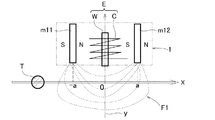
本発明をより具体的に説明する一実施例である磁気検査装置1の概要と、磁気検査装置1により異物T(鋼球)の有無を検出する様子を図1Aに示した。磁気検査装置1は、永久磁石m11(第1検査磁場源)と、永久磁石m12(第2検査磁場源)と、永久磁石m11、m12の中央に配設されたMI素子Eと、MI素子Eの駆動回路(図略)と、MI素子Eの出力に基づき異物Tの有無を判定する判定回路(図略/判定手段)とからなる。
Example 1
(1) Configuration of Magnetic Inspection Device FIG. 1A shows an outline of a
MI素子Eは、永久磁石m11、m12の中央を図中上下方向に延在するy軸(特定軸)上に配設された感磁ワイヤwと、この感磁ワイヤwの周囲を囲繞するピックアップコイルcとからなる。なお、感磁ワイヤwはCoFeSiB系合金製のほぼ零磁歪であるアモルファスワイヤからなる。 The MI element E includes a magnetic sensing wire w disposed on the y-axis (specific axis) extending in the vertical direction in the drawing in the center of the permanent magnets m11 and m12, and a pickup surrounding the magnetic sensing wire w. It consists of a coil c. The magnetosensitive wire w is made of an amorphous wire having a substantially zero magnetostriction made of a CoFeSiB alloy.
永久磁石m11、m12は、板状の希土類磁石からなり、異極同士(永久磁石m11のN極と永久磁石m12のS極)がy軸(特定軸)に垂直な方向に沿って対面配置されている。参考に、これら永久磁石m11、m12により生成される検査磁場F1を磁力線(破線)で示した。 The permanent magnets m11 and m12 are made of plate-like rare earth magnets, and different poles (N pole of the permanent magnet m11 and S pole of the permanent magnet m12) are arranged facing each other along a direction perpendicular to the y axis (specific axis). ing. For reference, the inspection magnetic field F1 generated by these permanent magnets m11 and m12 is indicated by magnetic lines (broken lines).
なお、MI素子E(感磁ワイヤwおよびピックアップコイルc)と駆動回路はシリコン基板上に形成されており、これらがMIセンサ(チップ)となる。なお、駆動回路は、感磁ワイヤwの両端電極に接続されてパルス電流を供給するパルス発振回路と、ピックアップコイルcで生じた電圧を所定タイミングでサンプリングし増幅して出力する信号処理回路とからなる。信号処理回路から得られた出力は、異物Tの有無を判定する判定回路へ入力される。 The MI element E (magnetic wire w and pickup coil c) and the drive circuit are formed on a silicon substrate, and these are the MI sensor (chip). The drive circuit includes a pulse oscillation circuit that is connected to both end electrodes of the magnetic sensing wire w and supplies a pulse current, and a signal processing circuit that samples, amplifies, and outputs the voltage generated in the pickup coil c at a predetermined timing. Become. The output obtained from the signal processing circuit is input to a determination circuit that determines the presence or absence of the foreign matter T.
(2)磁気検査装置による異物検出
図1Aに示すように、永久磁石m11、m12とMI素子Eの下方(図中)を、異物Tが矢印の方向(x軸方向)へ通過する場合を考える。先ず、異物Tが十分に遠方にあるときにおける検査磁場F1のy軸方向成分(特定磁気)を、その検査磁場F1中に配置したMI素子Eにより計測する。このとき得られた特定磁気を基準磁場(M0)とする。
(2) Foreign object detection by magnetic inspection apparatus As shown in FIG. 1A, a case where the foreign object T passes through the permanent magnets m11 and m12 and the MI element E (in the drawing) in the direction of the arrow (x-axis direction) is considered. . First, the y-axis direction component (specific magnetism) of the inspection magnetic field F1 when the foreign object T is sufficiently far away is measured by the MI element E arranged in the inspection magnetic field F1. The specific magnetism obtained at this time is set as a reference magnetic field (M0).
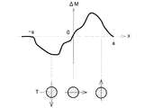
次に、ベルトコンベア等の搬送手段により異物Tを、図左側(x軸の負側)の遠方から図右側(x軸の正側)へゆっくりと移動させる。この移動に伴って異物Tの磁化状態(方向や強さ)が変化すると共に、異物Tの磁化状態の変化に伴ってMI素子Eにより検出される検査磁場F1のy軸方向の磁気成分である特定磁気(M)も変化する。 Next, the foreign matter T is slowly moved from the far side on the left side (the negative side of the x axis) to the right side (the positive side of the x axis) by transport means such as a belt conveyor. This is a magnetic component in the y-axis direction of the inspection magnetic field F1 detected by the MI element E along with the change in the magnetization state (direction and strength) of the foreign matter T along with this movement. The specific magnetism (M) also changes.
異物Tの移動に伴って、その特定磁気(M)が基準磁場(M0)に対して変化する様子(ΔM=M−M0)を図1Bに示した。なお、図1Bに示した波形は、MI素子Eの信号処理回路からの出力を、オシロスコープで観察した波形を模写したものである。また参考に、異物Tの各位置における磁化状態(方向)を図1Bの下方に示した。 FIG. 1B shows how the specific magnetism (M) changes with respect to the reference magnetic field (M0) as the foreign object T moves (ΔM = M−M0). The waveform shown in FIG. 1B is a copy of the waveform of the output from the signal processing circuit of the MI element E observed with an oscilloscope. For reference, the magnetization state (direction) at each position of the foreign matter T is shown below FIG. 1B.
図1Bからわかるように、検査磁場F1を異物Tが通過する際に、MI素子Eにより検出される特定磁気は負側(磁場が下向き)のピークから正側(磁場が上向き)のピークへ大きく変化することがわかる。磁気検査装置1は、そのような大きな特定磁気の変化量に基づいて被検出体の有無等を判定できるので、非常に高感度で高精度な検査が可能となる。
As can be seen from FIG. 1B, when the foreign substance T passes through the inspection magnetic field F1, the specific magnetism detected by the MI element E is greatly increased from a negative peak (magnetic field downward) to a positive peak (magnetic field upward). You can see that it changes. Since the
ちなみに、検査磁場F1は、永久磁石m11、m12により形成される磁場であって、異物Tの進入によりMI素子Eにより検出される特定磁気(y軸成分)が変動を生じる範囲内の磁場である。もっとも便宜的には、永久磁石m11の中央と永久磁石m12の中央との間(図1Aまたは図1Bに示したx軸方向の区間[−a、a])にできる磁場と考えてもよい。これは他の実施例でも同様である。 Incidentally, the inspection magnetic field F1 is a magnetic field formed by the permanent magnets m11 and m12, and is a magnetic field within a range in which the specific magnetism (y-axis component) detected by the MI element E due to the entry of the foreign matter T varies. . Most conveniently, it may be considered as a magnetic field that can be formed between the center of the permanent magnet m11 and the center of the permanent magnet m12 (section [-a, a] in the x-axis direction shown in FIG. 1A or FIG. 1B). The same applies to other embodiments.
《実施例2》
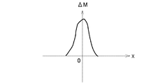
磁気検査装置1の永久磁石m11、永久磁石m12の形状と配置を変更した磁気検査装置2を図2Aに示した。磁気検査装置2を構成する永久磁石m21、m22は、棒状の希土類磁石からなり、図2Aに示すように、同極同士(永久磁石m21のN極と永久磁石m22のN極)をy軸(特定軸)に垂直な方向に沿って対面配置されている。参考に、これら永久磁石m21、m22により生成される検査磁場F2を磁力線(破線)で示した。なお、磁気検査装置1と同じ構成要素については、本実施例でも同符号を用いた。これは他の実施例でも同様である。
Example 2
A
異物Tの移動に伴って、磁気検査装置2のMI素子Eにより検出される特定磁気(M)の基準磁場(M0)に対する変化量(ΔM=M−M0)を図2Bに示した。磁気検査装置1と磁気検査装置2を比較すると、特定磁気の変化量に関する波形は異なるが、大きな特定磁気の変化量に基づいて被検出体の有無等を高感度、高精度に判定できる点は同様である。
FIG. 2B shows the amount of change (ΔM = M−M0) with respect to the reference magnetic field (M0) of the specific magnetism (M) detected by the MI element E of the
《実施例3》
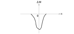
磁気検査装置3は、磁気検査装置1等とは異なり、図3Aに示すように、棒状の希土類磁石からなる一つの永久磁石m3をy軸(特定軸)に沿って配置してなる。参考に、これら永久磁石m3により生成される検査磁場F3を磁力線(破線)で示した。また、異物Tの移動に伴って、磁気検査装置3のMI素子Eにより検出される特定磁気(M)の基準磁場(M0)に対する変化量(ΔM=M−M0)を図3Bに示した。この場合も、特定磁気の変化量に関する波形は他の実施例と異なるが、大きな特定磁気の変化量に基づいて被検出体の有無等を高感度、高精度に判定できる点は他の実施例と同様である。なお、図3Aでは永久磁石m3のN極を上方に向けたが、S極を上方に向けてもよい。MI素子Eへ向ける磁極を変更することにより、図3Bに示した波形が上下逆転することになる。
Example 3
Unlike the
《実施例4》
磁気検査装置4は、図4Aに示すように、棒状の希土類磁石からなる永久磁石m41と永久磁石m42を、y軸(特定軸)に沿いつつy軸を中央に挟むように並列配置してなる。参考に、これら永久磁石m41、m42により生成される検査磁場F4を磁力線(破線)で示した。また、異物Tの移動に伴って、磁気検査装置4のMI素子Eにより検出される特定磁気(M)の基準磁場(M0)に対する変化量(ΔM=M−M0)を図4Bに示した。この場合も、特定磁気の変化量に関する波形は他の実施例と異なるが、大きな特定磁気の変化量に基づいて被検出体の有無等を高感度、高精度に判定できる点は他の実施例と同様である。なお図4Aでは、永久磁石m41と永久磁石m42を異極同士で接するように配置したが、永久磁石m41と永久磁石m42を同極同士で接するように配置してもよい。
Example 4
As shown in FIG. 4A, the
《実施例5》
磁気検査装置5は、図5Aに示すように、棒状の希土類磁石からなる永久磁石m51と永久磁石m52を、y軸(特定軸)に沿って異極同士で対向するように上下に配置してなる。参考に、これら永久磁石m51、m52により生成される検査磁場F5を磁力線(破線)で示した。また、異物Tの移動に伴って、磁気検査装置5のMI素子Eにより検出される特定磁気(M)の基準磁場(M0)に対する変化量(ΔM=M−M0)を図5Bに示した。この場合も、特定磁気の変化量に関する波形は他の実施例と異なるが、大きな特定磁気の変化量に基づいて被検出体の有無等を高感度、高精度に判定できる点は他の実施例と同様である。
Example 5
As shown in FIG. 5A, the
《実施例6》
磁気検査装置6は、磁気検査装置5の永久磁石m51、m52の配置とMI素子Eの配置を変更したものである。すなわち、図6Aに示すように、棒状の希土類磁石からなる永久磁石m61と永久磁石m62を、y軸(特定軸)に沿って同極同士で対向するように上下に配置すると共に、MI素子Eを下方側の永久磁石m62寄り(異物Tの奇跡により近い側)へ配置した。参考に、これら永久磁石m61、m62により生成される検査磁場F6を磁力線(破線)で示した。また、異物Tの移動に伴って、磁気検査装置6のMI素子Eにより検出される特定磁気(M)の基準磁場(M0)に対する変化量(ΔM=M−M0)を図6Bに示した。この場合も、特定磁気の変化量に関する波形は他の実施例と異なるが、大きな特定磁気の変化量に基づいて被検出体の有無等を高感度、高精度に判定できる点は他の実施例と同様である。
Example 6
The
《実施例7》
磁気検査装置7は、図7Aに示すように、棒状の希土類磁石からなる永久磁石m71と永久磁石m72を、y軸(特定軸)の斜め方向に沿って異極同士で対向配置してなる。参考に、これら永久磁石m71、m72により生成される検査磁場F7を磁力線(破線)で示した。また、異物Tの移動に伴って、磁気検査装置7のMI素子Eにより検出される特定磁気(M)の基準磁場(M0)に対する変化量(ΔM=M−M0)を図7Bに示した。この場合も、特定磁気の変化量に関する波形は他の実施例と異なるが、大きな特定磁気の変化量に基づいて被検出体の有無等を高感度、高精度に判定できる点は他の実施例と同様である。
Example 7
As shown in FIG. 7A, the
《実施例8》
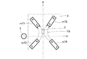
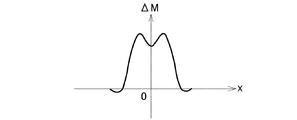
磁気検査装置8は、図8Aに示すように、棒状の希土類磁石からなる4つの永久磁石m81、m82、m83、m84を、y軸(特定軸)対称にして、クロス状(X状)に配置してなる。本実施例では、永久磁石m81と永久磁石m82のS極同士を内側にして配置すると共に、永久磁石m83と永久磁石m84のN極同士を内側にして配置した。参考に、これら永久磁石m81、m82、m83、m84により生成される検査磁場F8を磁力線(破線)で示した。また、異物Tの移動に伴って、磁気検査装置8のMI素子Eにより検出される特定磁気(M)の基準磁場(M0)に対する変化量(ΔM=M−M0)を図8Bに示した。この場合も、特定磁気の変化量に関する波形は他の実施例と異なるが、大きな特定磁気の変化量に基づいて被検出体の有無等を高感度、高精度に判定できる点は他の実施例と同様である。
Example 8
As shown in FIG. 8A, the magnetic inspection apparatus 8 is arranged in a cross shape (X shape) with four permanent magnets m81, m82, m83, and m84 made of rod-shaped rare earth magnets symmetrical with respect to the y axis (specific axis). Do it. In the present embodiment, the S poles of the permanent magnet m81 and the permanent magnet m82 are arranged inside, and the N poles of the permanent magnet m83 and the permanent magnet m84 are arranged inside. For reference, the inspection magnetic field F8 generated by these permanent magnets m81, m82, m83, and m84 is indicated by magnetic lines (broken lines). FIG. 8B shows the amount of change (ΔM = M−M0) with respect to the reference magnetic field (M0) of the specific magnetism (M) detected by the MI element E of the magnetic inspection apparatus 8 as the foreign object T moves. In this case as well, the waveform related to the amount of change in the specific magnetism is different from that in the other embodiments. It is the same.
以上のように検査磁場源の配置やMI素子の配置は種々あり得るが、いずれの場合であっても、本発明の磁気検査装置によれば高感度で高精度な被検出体の検出、識別等が可能となる。 As described above, there can be various arrangements of inspection magnetic field sources and MI elements. In any case, according to the magnetic inspection apparatus of the present invention, detection and identification of a detection object with high sensitivity and high accuracy are possible. Etc. are possible.
1 磁気検査装置
E MI素子
m1、m2 永久磁石(検査磁場源)
F1 検査磁場
T 異物(被検出体)
1 Magnetic inspection device E MI element m1, m2 Permanent magnet (inspection magnetic field source)
F1 Inspection magnetic field T Foreign object (object to be detected)
Claims (5)
該検査磁場内の特定軸方向に延在し該特定軸方向の磁気である特定磁気に感応してインピーダンスを変化させ得る感磁体を有するマグネトインピーダンス素子とを備え、
該検査対象物が該マグネトインピーダンス素子または該検査磁場源に対して相対移動することにより、該検査磁場内で該被検出体により誘起される該特定磁気の変化に基づき、該検査対象物内における該被検出体の存在状況を把握し得ることを特徴とする磁気検査装置。 An inspection magnetic field source for generating an inspection magnetic field applied to a detection object made of a magnetic material included in the inspection object;
A magneto-impedance element having a magnetosensitive body that extends in a specific axis direction in the inspection magnetic field and can change impedance in response to specific magnetism that is magnetism in the specific axis direction;
The inspection object moves relative to the magneto-impedance element or the inspection magnetic field source, and based on the change in the specific magnetism induced by the detected object in the inspection magnetic field, A magnetic inspection apparatus capable of grasping the presence state of the detected object.
前記マグネトインピーダンス素子は、該第1検査磁場源と該第2検査磁場源の中間に配設される請求項1に記載の磁気検査装置。 The inspection magnetic field source comprises at least a first inspection magnetic field source and a second inspection magnetic field source,
The magnetic inspection apparatus according to claim 1, wherein the magneto-impedance element is disposed between the first inspection magnetic field source and the second inspection magnetic field source.
該移動ステップ中に該検査磁場内で該被検出体により誘起される該特定磁気の変化を該マグネトインピーダンス素子により検出する検出ステップとを備え、
該特定磁気の変化に基づき該検査対象物内における該被検出体の存在状況を把握し得ることを特徴とする磁気検査方法。 An inspection magnetic field source that generates an inspection magnetic field to be applied to an inspection object that can include an object to be detected made of a magnetic material, or a specific magnetic field that extends in a specific axis direction in the inspection magnetic field and is a magnetism in the specific axis direction. A moving step capable of moving the test object relative to a magneto-impedance element having a magnetosensitive element capable of changing impedance.
A detection step of detecting, by the magneto-impedance element, a change in the specific magnetism induced by the detected object in the inspection magnetic field during the moving step;
A magnetic inspection method characterized in that the presence state of the detected object in the inspection object can be grasped based on the change in the specific magnetism.
Priority Applications (1)
| Application Number | Priority Date | Filing Date | Title |
|---|---|---|---|
| JP2013135651A JP6149542B2 (en) | 2013-06-27 | 2013-06-27 | Magnetic inspection apparatus and magnetic inspection method |
Applications Claiming Priority (1)
| Application Number | Priority Date | Filing Date | Title |
|---|---|---|---|
| JP2013135651A JP6149542B2 (en) | 2013-06-27 | 2013-06-27 | Magnetic inspection apparatus and magnetic inspection method |
Publications (2)
| Publication Number | Publication Date |
|---|---|
| JP2015010902A true JP2015010902A (en) | 2015-01-19 |
| JP6149542B2 JP6149542B2 (en) | 2017-06-21 |
Family
ID=52304191
Family Applications (1)
| Application Number | Title | Priority Date | Filing Date |
|---|---|---|---|
| JP2013135651A Active JP6149542B2 (en) | 2013-06-27 | 2013-06-27 | Magnetic inspection apparatus and magnetic inspection method |
Country Status (1)
| Country | Link |
|---|---|
| JP (1) | JP6149542B2 (en) |
Cited By (6)
| Publication number | Priority date | Publication date | Assignee | Title |
|---|---|---|---|---|
| WO2017213005A1 (en) * | 2016-06-09 | 2017-12-14 | 愛知製鋼株式会社 | Magnetic field measurement device |
| JP2019027985A (en) * | 2017-08-02 | 2019-02-21 | アンリツインフィビス株式会社 | Metal detection apparatus and metal detection method |
| CN109765503A (en) * | 2019-02-01 | 2019-05-17 | 昆山国显光电有限公司 | A kind of process cavity and fragmentation inspection method with fragmentation detection |
| EP3346298A4 (en) * | 2015-10-06 | 2019-06-12 | Aichi Steel Corporation | MAGNETIC MICROSUBSTANCE DETECTION SENSOR AND FOREIGN BODY DETECTION APPARATUS |
| WO2020110407A1 (en) * | 2018-11-29 | 2020-06-04 | 昭和電工株式会社 | Magnetic sensor and magnetic sensor manufacturing method |
| WO2021199757A1 (en) * | 2020-03-30 | 2021-10-07 | 三菱電機株式会社 | Magnetic sensor device |
Citations (6)
| Publication number | Priority date | Publication date | Assignee | Title |
|---|---|---|---|---|
| JPS52118652U (en) * | 1976-03-05 | 1977-09-08 | ||
| JPH11183195A (en) * | 1997-12-22 | 1999-07-09 | Sony Precision Technology Inc | Magnetic metal sensor and magnetic metal detecting method |
| JP2004121667A (en) * | 2002-10-04 | 2004-04-22 | Olympus Corp | Instrument for detecting magnetic fluid |
| JP2008249583A (en) * | 2007-03-30 | 2008-10-16 | Deed Corp | Magnetic object detector |
| JP2009300331A (en) * | 2008-06-16 | 2009-12-24 | Japan Oil Gas & Metals National Corp | Magnetic field sensor device |
| US20120038354A1 (en) * | 2006-12-21 | 2012-02-16 | Gies Paul D | Linear structure inspection apparatus and method |
-
2013
- 2013-06-27 JP JP2013135651A patent/JP6149542B2/en active Active
Patent Citations (6)
| Publication number | Priority date | Publication date | Assignee | Title |
|---|---|---|---|---|
| JPS52118652U (en) * | 1976-03-05 | 1977-09-08 | ||
| JPH11183195A (en) * | 1997-12-22 | 1999-07-09 | Sony Precision Technology Inc | Magnetic metal sensor and magnetic metal detecting method |
| JP2004121667A (en) * | 2002-10-04 | 2004-04-22 | Olympus Corp | Instrument for detecting magnetic fluid |
| US20120038354A1 (en) * | 2006-12-21 | 2012-02-16 | Gies Paul D | Linear structure inspection apparatus and method |
| JP2008249583A (en) * | 2007-03-30 | 2008-10-16 | Deed Corp | Magnetic object detector |
| JP2009300331A (en) * | 2008-06-16 | 2009-12-24 | Japan Oil Gas & Metals National Corp | Magnetic field sensor device |
Cited By (13)
| Publication number | Priority date | Publication date | Assignee | Title |
|---|---|---|---|---|
| EP3346298A4 (en) * | 2015-10-06 | 2019-06-12 | Aichi Steel Corporation | MAGNETIC MICROSUBSTANCE DETECTION SENSOR AND FOREIGN BODY DETECTION APPARATUS |
| US10539701B2 (en) | 2015-10-06 | 2020-01-21 | Aichi Steel Corporation | Minute magnetic body detecting sensor and foreign substance detecting device |
| JP2017219456A (en) * | 2016-06-09 | 2017-12-14 | 愛知製鋼株式会社 | Magnetic field measurement device |
| WO2017213005A1 (en) * | 2016-06-09 | 2017-12-14 | 愛知製鋼株式会社 | Magnetic field measurement device |
| JP2019027985A (en) * | 2017-08-02 | 2019-02-21 | アンリツインフィビス株式会社 | Metal detection apparatus and metal detection method |
| US11525871B2 (en) | 2018-11-29 | 2022-12-13 | Showa Denko K. K. | Magnetic sensor and magnetic sensor manufacturing method |
| WO2020110407A1 (en) * | 2018-11-29 | 2020-06-04 | 昭和電工株式会社 | Magnetic sensor and magnetic sensor manufacturing method |
| JP2020085766A (en) * | 2018-11-29 | 2020-06-04 | 昭和電工株式会社 | Magnetic sensor and method of manufacturing magnetic sensor |
| JP7259293B2 (en) | 2018-11-29 | 2023-04-18 | 株式会社レゾナック | Magnetic sensor and method for manufacturing magnetic sensor |
| CN109765503A (en) * | 2019-02-01 | 2019-05-17 | 昆山国显光电有限公司 | A kind of process cavity and fragmentation inspection method with fragmentation detection |
| JP6980166B1 (en) * | 2020-03-30 | 2021-12-15 | 三菱電機株式会社 | Magnetic sensor device |
| WO2021199757A1 (en) * | 2020-03-30 | 2021-10-07 | 三菱電機株式会社 | Magnetic sensor device |
| US11639974B1 (en) | 2020-03-30 | 2023-05-02 | Mitsubishi Electric Corporation | Magnetic sensor device |
Also Published As
| Publication number | Publication date |
|---|---|
| JP6149542B2 (en) | 2017-06-21 |
Similar Documents
| Publication | Publication Date | Title |
|---|---|---|
| JP6149542B2 (en) | Magnetic inspection apparatus and magnetic inspection method | |
| US10109131B2 (en) | Sensor device including magnetoresistive sensor element and pre-magnetization device | |
| JP2017072456A5 (en) | ||
| JP2017072456A (en) | Minute magnetic material detection sensor and foreign matter detection device | |
| JP2009163336A (en) | Magnetic pattern detection device | |
| JP5889697B2 (en) | Paper sheet magnetism evaluation apparatus and paper sheet magnetism evaluation method | |
| CN103238064A (en) | Quenching depth measuring method and quenching depth measuring device | |
| JP6300908B2 (en) | Magnetic sensor device | |
| CN105974338B (en) | Magnetic Sensor | |
| RU2648010C2 (en) | Metering device for measuring the magnetic properties of environment of the metering device | |
| JP2017150904A (en) | Flaw detection apparatus and flaw detection method | |
| US11237227B2 (en) | Magnetic sensor | |
| CN108156821A (en) | Magnet sensor arrangement | |
| EP3159854B1 (en) | Coin detection system | |
| JP2015124999A (en) | Magnetic detection device and magnetic substance presence inspection device | |
| Marchand et al. | Innovative flexible eddy current probes for the inspection of complex parts | |
| JP2014010118A (en) | Magnetic sensor device | |
| US10884076B2 (en) | MI magnetic field sensor | |
| JP6075225B2 (en) | Magnetic sensor device | |
| CN204129826U (en) | A kind of Detecting of coin system | |
| JP6460079B2 (en) | MI magnetic sensor | |
| JP2006322860A (en) | Eddy current flaw detection probe | |
| JP2016095138A (en) | Magnetic sensor | |
| JP4805631B2 (en) | Magnetic body analyzing apparatus and magnetic body analyzing method | |
| US20130124101A1 (en) | Method for detecting magnetically marked objects and corresponding device |
Legal Events
| Date | Code | Title | Description |
|---|---|---|---|
| A621 | Written request for application examination |
Free format text: JAPANESE INTERMEDIATE CODE: A621 Effective date: 20160204 |
|
| A977 | Report on retrieval |
Free format text: JAPANESE INTERMEDIATE CODE: A971007 Effective date: 20160920 |
|
| A131 | Notification of reasons for refusal |
Free format text: JAPANESE INTERMEDIATE CODE: A131 Effective date: 20160927 |
|
| A521 | Request for written amendment filed |
Free format text: JAPANESE INTERMEDIATE CODE: A523 Effective date: 20161118 |
|
| TRDD | Decision of grant or rejection written | ||
| A01 | Written decision to grant a patent or to grant a registration (utility model) |
Free format text: JAPANESE INTERMEDIATE CODE: A01 Effective date: 20170425 |
|
| A61 | First payment of annual fees (during grant procedure) |
Free format text: JAPANESE INTERMEDIATE CODE: A61 Effective date: 20170508 |
|
| R150 | Certificate of patent or registration of utility model |
Ref document number: 6149542 Country of ref document: JP Free format text: JAPANESE INTERMEDIATE CODE: R150 |
|
| R250 | Receipt of annual fees |
Free format text: JAPANESE INTERMEDIATE CODE: R250 |
|
| R250 | Receipt of annual fees |
Free format text: JAPANESE INTERMEDIATE CODE: R250 |
|
| R250 | Receipt of annual fees |
Free format text: JAPANESE INTERMEDIATE CODE: R250 |
|
| R250 | Receipt of annual fees |
Free format text: JAPANESE INTERMEDIATE CODE: R250 |
|
| R250 | Receipt of annual fees |
Free format text: JAPANESE INTERMEDIATE CODE: R250 |
|
| R250 | Receipt of annual fees |
Free format text: JAPANESE INTERMEDIATE CODE: R250 |
|
| R250 | Receipt of annual fees |
Free format text: JAPANESE INTERMEDIATE CODE: R250 |