JP2015092425A - Stopper and disk drive - Google Patents
Stopper and disk drive Download PDFInfo
- Publication number
- JP2015092425A JP2015092425A JP2014121947A JP2014121947A JP2015092425A JP 2015092425 A JP2015092425 A JP 2015092425A JP 2014121947 A JP2014121947 A JP 2014121947A JP 2014121947 A JP2014121947 A JP 2014121947A JP 2015092425 A JP2015092425 A JP 2015092425A
- Authority
- JP
- Japan
- Prior art keywords
- stopper
- rail
- disk drive
- pickup
- exterior
- Prior art date
- Legal status (The legal status is an assumption and is not a legal conclusion. Google has not performed a legal analysis and makes no representation as to the accuracy of the status listed.)
- Granted
Links
Images

Classifications
-
- G—PHYSICS
- G11—INFORMATION STORAGE
- G11B—INFORMATION STORAGE BASED ON RELATIVE MOVEMENT BETWEEN RECORD CARRIER AND TRANSDUCER
- G11B33/00—Constructional parts, details or accessories not provided for in the other groups of this subclass
- G11B33/14—Reducing influence of physical parameters, e.g. temperature change, moisture, dust
-
- G—PHYSICS
- G11—INFORMATION STORAGE
- G11B—INFORMATION STORAGE BASED ON RELATIVE MOVEMENT BETWEEN RECORD CARRIER AND TRANSDUCER
- G11B17/00—Guiding record carriers not specifically of filamentary or web form, or of supports therefor
- G11B17/02—Details
- G11B17/04—Feeding or guiding single record carrier to or from transducer unit
- G11B17/05—Feeding or guiding single record carrier to or from transducer unit specially adapted for discs not contained within cartridges
- G11B17/053—Indirect insertion, i.e. with external loading means
- G11B17/056—Indirect insertion, i.e. with external loading means with sliding loading means
-
- F—MECHANICAL ENGINEERING; LIGHTING; HEATING; WEAPONS; BLASTING
- F16—ENGINEERING ELEMENTS AND UNITS; GENERAL MEASURES FOR PRODUCING AND MAINTAINING EFFECTIVE FUNCTIONING OF MACHINES OR INSTALLATIONS; THERMAL INSULATION IN GENERAL
- F16F—SPRINGS; SHOCK-ABSORBERS; MEANS FOR DAMPING VIBRATION
- F16F7/00—Vibration-dampers; Shock-absorbers
-
- G—PHYSICS
- G11—INFORMATION STORAGE
- G11B—INFORMATION STORAGE BASED ON RELATIVE MOVEMENT BETWEEN RECORD CARRIER AND TRANSDUCER
- G11B33/00—Constructional parts, details or accessories not provided for in the other groups of this subclass
- G11B33/005—Means for locking the disc or cassette receiving slot, e.g. dummy cassettes locked in the slot
Landscapes
- Engineering & Computer Science (AREA)
- General Engineering & Computer Science (AREA)
- Mechanical Engineering (AREA)
- Supporting Of Heads In Record-Carrier Devices (AREA)
- Feeding And Guiding Record Carriers (AREA)
Abstract
Description
本開示は、ディスクドライブのヘッドを固定するストッパーに関する。 The present disclosure relates to a stopper for fixing a head of a disk drive.
特許文献1は、光ディスク装置のヘッド固定手段を開示している。ヘッド固定手段は、光ディスク装置の移動時に光ヘッドを装置内部に固定するために、光ディスク装置内のディスクカートリッジ収納部に袋体を挿入、配置し、袋体にエアーを充填することで、光ヘッドを保持固定する。 Patent Document 1 discloses a head fixing means of an optical disk device. The head fixing means inserts and disposes a bag body in the disk cartridge housing portion in the optical disk apparatus and fixes the optical head to the inside of the apparatus when the optical disk apparatus is moved. Hold and fix.
本開示は、ディスクドライブのピックアップの移動を規制し、さらに、ディスクドライブから除去が容易なストッパーを提供する。 The present disclosure provides a stopper that regulates the movement of the pickup of the disk drive and is easily removed from the disk drive.
本開示におけるディスクドライブのストッパーにおいて、ディスクドライブは、一側面に開口を有する、箱型の外装と、外装に収容され、載置面を有するトレイと、ピックアップと、ピックアップが移動する経路として、載置面に形成された窪みであるレールと、を有し、ストッパーは、平板への復元性を有するシート部材であり、折り曲げることで、規制部と中継部とつまみ部とを構成し、ディスクドライブに収容される場合は、規制部は、レールの内部に配置され、中継部は、載置面の上に配置され、つまみ部は、トレイと外装との間に生じる隙間から突出するように配置される。 In the disk drive stopper according to the present disclosure, the disk drive is mounted as a box-shaped exterior having an opening on one side, a tray housed in the exterior and having a placement surface, a pickup, and a path along which the pickup moves. A stopper formed on the mounting surface, and the stopper is a sheet member having a restoring property to a flat plate, and is bent to constitute a regulating portion, a relay portion, and a knob portion. In the case of being housed in the housing, the restricting portion is disposed inside the rail, the relay portion is disposed on the mounting surface, and the knob portion is disposed so as to protrude from a gap generated between the tray and the exterior. Is done.
本開示におけるストッパーは、ディスクドライブのピックアップの移動を規制し、さらに、ディスクドライブから除去が容易である。 The stopper in the present disclosure regulates the movement of the disk drive pickup and is easily removed from the disk drive.
以下、適宜図面を参照しながら、実施の形態を詳細に説明する。但し、必要以上に詳細な説明は省略する場合がある。例えば、既によく知られた事項の詳細説明や実質的に同一の構成に対する重複説明を省略する場合がある。これは、以下の説明が不必要に冗長になるのを避け、当業者の理解を容易にするためである。 Hereinafter, embodiments will be described in detail with reference to the drawings as appropriate. However, more detailed description than necessary may be omitted. For example, detailed descriptions of already well-known matters and repeated descriptions for substantially the same configuration may be omitted. This is to avoid the following description from becoming unnecessarily redundant and to facilitate understanding by those skilled in the art.
なお、添付図面および以下の説明は、当業者が本開示を十分に理解するために、提供されるのであって、これらにより特許請求の範囲に記載の主題を限定することは意図されていない。 The accompanying drawings and the following description are provided to enable those skilled in the art to fully understand the present disclosure, and are not intended to limit the subject matter described in the claims.
(実施の形態)
以下、図1〜6を用いて、実施の形態を説明する。
(Embodiment)
Hereinafter, embodiments will be described with reference to FIGS.
[1−1.構成]
[1−1−1.全体構成]
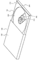
図1は、実施の形態における全体構成の外観図である。
[1-1. Constitution]
[1-1-1. overall structure]
FIG. 1 is an external view of the overall configuration in the embodiment.
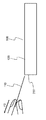
ディスクドライブ100は、図示しないディスクを収容する。ディスクドライブ100はディスクへ情報を記録し、ディスクから情報を読み取る装置である。ディスクドライブ100にストッパー110が収容されている。ディスクドライブ100は、外装120とトレイ130を有する。トレイ130は、外装120に収容されている。
The
ストッパー110は、つまみ部140を有し、つまみ部140は、ディスクドライブ100の外装120とディスクドライブ100のトレイ130との間に生じる隙間から外部に向かって突出した部分である。
The
[1−1−2.ディスクドライブの構成]
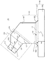
図2は、実施の形態におけるディスクドライブ100の構成図である。
[1-1-2. Disk drive configuration]
FIG. 2 is a configuration diagram of the
外装120は、略箱型であり、1側面、図2では右側の側面、は開口している。
The
トレイ130は、外装120の開口から外装120の内部に移動可能となっている。図2では、トレイ130の一部のみが外装120に収容され、大半が外装120から突出している。トレイ130は、主面210と、載置面220と、ピックアップ230と、レール240と、蓋250を有する。
The
載置面220は、主面210よりも凹んでおり、凹みは略円形である。載置面220にはディスクが載置される。
The
ピックアップ230は、載置面220に載置されたディスクに対して、データの読み書きを行う。ピックアップ230は、載置面220に形成された窪みであるレール240の内部に配置される。ピックアップ230は、図示しないアクチュエータによってレール240の内部をレール240に沿って移動可能である。
The
蓋250は、トレイ130が外装120に収容されている時に外装120の開口を閉塞する。蓋250の上端面は主面210よりも若干高くなっている。
The
[1−1−3.ストッパーの構成]
図3は、実施の形態におけるストッパー110の平面図であり、図4は、実施の形態におけるストッパー110の立体構造を示す図である。
[1-1-3. Stopper configuration]
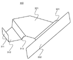
FIG. 3 is a plan view of the
ストッパー110は、平板のシート部材を折り曲げることによって形成される。図3は、折り曲げられる前のストッパー110を示している。シート部材は、平板への復元性を有している。ここで平板への復元性とは、折り曲げられた状態において他端を固定して一端を引っ張った際に、折り曲げられた状態から平板のシート部材の状態へ戻ることができるということであり、完全に平板に戻らなくてもよい。後述するように、ストッパー110をディスクドライブ100から少なくとも引く抜くことが出来る程度、すなわち、外装120と蓋250の間の隙間をすり抜ける程度の厚みに復元する程度の平板への復元性があればよい。本実施の形態では、ストッパー110の材料として、厚さ0.2mmのプラスチックシートを用いた。ストッパー110の材料は、プラスチックシートに限定されない。ストッパー110の材料としては平板への復元性を有するものであれば、何でもよく、例えば、紙等の繊維シート、金属箔などでもよい。
The
ストッパー110は、つまみ部140と、規制部310と、規制部310とつまみ部140の中間に位置する中継部320を有する。
The
ストッパー110は、折り線L1、L2、L3、L4、L5、L6に沿って折り曲げられる。
The
規制部310は、第1の側面311と、底面312と、第2の側面313を有する。
The restricting
第1の側面311と底面312の境界の折り線L1は、谷折りである。底面312と第2の側面313の境界の折り線L2は、谷折りである。規制部310は、折り線L1と折り線L2が略90度に折り曲げられることで、略U字断面の立体構造に形成される。
The fold line L1 at the boundary between the
規制部310は、ディスクドライブ100のレール240の内部に配置される。
The
第1の側面311は、レール240の高さと略同じ高さH1である。底面312は、レール240の幅より短い幅W1である。第2の側面313は、レール240の高さと略同じ高さH2である。
The
中継部320は、ディスクドライブ100の載置面220の上に一部が配置される。中継部320は、屈曲部321と段差部322を有する。屈曲部321と規制部310の第2の側面313の境界の折り線L3は、山折りである。屈曲部321と段差部322の境界の折り線L4は、谷折りである。段差部322は蓋250の高さのうちの主面210からの高さよりわずかに高い高さH3である。中継部320は、折り線L3と折り線L4がそれぞれ略90度折り曲げられることで、L字を90度反転させた型の立体構造に形成される。
A part of the
つまみ部140は、トレイ130と外装120との間に生じる隙間から突出する箇所である。つまみ部140は、天井部331と操作部332を有する。天井部331と中継部320の段差部322の境界の折り線L5は山折りである。天井部331と操作部332の境界の折り線L6は山折りである。天井部331は、蓋250の厚みと略同じ幅の幅W2である。操作部332の高さH4は、ディスクドライブ100から取り出し易い長さであることが好ましい。本実施の形態においては操作部332の高さH4は1cmとした。
The
図3に示すストッパー110の折り線L1、L2、L3、L4、L5、L6を折り曲げることで図4に示すようなストッパー110の立体構造が完成する。
The folding structure of the
[1−1−4.ディスクドライブ内部の構成]
図5は、実施の形態におけるストッパー110が折り曲げられてディスクドライブ100に収容された様子を示す図である。
[1-1-4. Internal disk drive configuration]
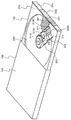
FIG. 5 is a diagram illustrating a state in which the
ストッパー110の規制部310は、ディスクドライブ100のレール240の内部に配置される。規制部310の第2の側面313は、レール240の側端に当接している。第1の側面の一端311aと、第2の側面の一端313aが、ピックアップ230に当接する。第1の側面の一端311aと、第2の側面の一端313aは、レール240の底面、規制部310の底面312が重畳する部分、からレール240の上方に向けて、底面312から折り曲げられた箇所である。第2の側面の他端313bは、レールの終端240aと当接する。
The
屈曲部321は、載置面220および主面210の上に配置される。
The
つまみ部140の天井部331は、蓋250の上端面に配置される。つまみ部140の操作部332は、蓋250の外面に配置される。
The
[1−2.作用]
[1−2−1.ピックアップに外力が加わった際の作用]
図5を用いて、ピックアップ230に外力F1が加わった際の作用を説明する。図5において便宜上、トレイ130が外装120から突出した状態でピックアップ230に外力F1が加わった際の作用を説明するが、トレイ130が外装120に収容された状態でも同様の作用が生じる。
[1-2. Action]
[1-2-1. Action when external force is applied to the pickup]
The operation when the external force F1 is applied to the
外力F1は、ピックアップ230がレールの終端240aの方向に移動しようとする力である。外力F1が加わる状況として、例えば、ディスクドライブ100を輸送中に、ディスクドライブ100が落下する状況や、ディスクドライブ100が他の物体と衝突するような状況がある。外力F1が加わる状況を避けるため、ディスクドライブ100内にストッパー110を収容する。
The external force F1 is a force that the
外力F1がピックアップ230に作用すると、ピックアップ230は、レール240に沿って移動しようとする。しかし、図5に示すようにピックアップ230には第1の側面の一端311aと、第2の側面の一端313aが当接しているので、ピックアップ230の移動が規制される。また、第2の側面の他端313bが、レールの終端240aと当接しているので、ストッパー110そのものがピックアップ230に押されて外力F1の方向へ移動する量も微量である。
When the external force F1 acts on the
[1−2−2.ストッパーをディスクドライブから引き抜く際の作用]
図6は、実施の形態におけるディスクドライブ100からストッパー110を除去する様子を示した図である。図1の状態からつまみ部140をつまみ、方向F2に引き抜くことで、ストッパー110がディスクドライブ100から除去される。ストッパー110が平板への復元性を有するので、折り曲げられた状態から方向F2へ引っ張ることで、ストッパー110が略平板形状に変形し、ストッパー110が外装120と蓋250との間に生じる隙間を通り抜ける。
[1-2-2. Action when pulling out the stopper from the disk drive]
FIG. 6 is a diagram showing how the
[1−3.効果等]
以上のように、本実施の形態のディスクドライブ100のストッパー110において、ディスクドライブ100は、一側面に開口を有する、箱型の外装120と、外装120に収容され、載置面220を有するトレイ130と、ピックアップ230と、ピックアップ230が移動する経路として、載置面220に形成された窪みであるレール240とを有し、ストッパー110は、平板への復元性を有するシート部材であり、折り曲げることで、規制部310と中継部320とつまみ部140とを構成し、ディスクドライブ100に収容される場合は、規制部310は、レール240の内部に配置され、中継部320は、載置面220の上に配置され、つまみ部140は、トレイ130と外装120との間に生じる隙間から突出するように配置される。
[1-3. Effect]
As described above, in the
これにより、ピックアップ230が、ストッパー110によって外力F1に向かう方向への移動を規制されるため、ピックアップ230がレールの終端240aに衝突し、ピックアップ230の機能が損なわれる可能性が低減する。そして、つまみ部140をつまみ、方向F2に引き抜くことでストッパー110は、ディスクドライブ100から除去できる。そのため、ストッパー110は、ディスクドライブ100から容易に除去できる。
Thereby, since the
また、本実施の形態において、規制部310は、レール240の内部で少なくとも1箇所が折り曲げられている。これにより、ストッパー110の構造を強固にしつつ、レール240内へのストッパー110の収容性を向上させることができる。
Further, in the present embodiment, at least one portion of the restricting
また、本実施の形態において、規制部310は、レール240の底面からレール240の上方に向けて折り曲げられた箇所である第1の側面311、第2の側面313を有する。これにより、規制部310の一部がピックアップ230とレール240の側面とに生じる隙間に巻込まれる可能性が低減する。
In the present embodiment, the restricting
また、本実施の形態において、規制部310の一端は、ピックアップ230と当接する。これにより、外力F1が加わる前であってもピックアップ230の移動を規制することが可能になるので、外力F1によりピックアップ230の移動量を削減できる。
In the present embodiment, one end of the restricting
また、本実施の形態において、規制部310の一端は、レールの終端240aと当接する。これにより、ピックアップ230の移動によって、ストッパー110がレールの終端240aの方向へ移動する可能性を低減できる。
In the present embodiment, one end of the restricting
本開示は、ディスクドライブのヘッドを固定するストッパーに適用可能である。ディスクドライブとして、具体的には、パーソナルコンピュータへの供給部品としてのディスクドライブ、タブレット端末へ接続される外付けディスクドライブ、携帯音楽プレーヤーなどに適用可能である。 The present disclosure is applicable to a stopper that fixes a head of a disk drive. As a disk drive, specifically, it can be applied to a disk drive as a supply part to a personal computer, an external disk drive connected to a tablet terminal, a portable music player, and the like.
100 ディスクドライブ
110 ストッパー
140 つまみ部
120 外装
130 トレイ
220 載置面
230 ピックアップ
240 レール
240a レールの終端
250 蓋
310 規制部
311 第1の側面
311a 第1の側面の一端
312 底面
313 第2の側面
313a 第2の側面の一端
313b 第2の側面の他端
320 中継部
321 屈曲部
322 段差部
331 天井部
332 操作部
DESCRIPTION OF
Claims (6)
前記ディスクドライブは、
一側面に開口を有する、箱型の外装と、
前記外装に収容され、載置面を有するトレイと、
ピックアップと、
前記ピックアップが移動する経路として、前記載置面に形成された窪みであるレールと、
を有し、
前記ストッパーは、
平板への復元性を有するシート部材であり、折り曲げることで、規制部と中継部とつまみ部とを構成し、
前記ディスクドライブに収容される場合は、
前記規制部は、前記レールの内部に配置され、
前記中継部は、前記載置面の上に配置され、
前記つまみ部は、前記トレイと前記外装との間に生じる隙間から突出するように配置される、
ストッパー。 A disk drive stopper,
The disk drive is
A box-shaped exterior having an opening on one side;
A tray housed in the exterior and having a mounting surface;
With a pickup,
As a path for the pickup to move, a rail that is a depression formed in the mounting surface,
Have
The stopper is
It is a sheet member that has a restoring property to a flat plate, and by bending, it constitutes a regulating part, a relay part, and a knob part,
When accommodated in the disk drive,
The restricting portion is disposed inside the rail,
The relay unit is disposed on the mounting surface,
The knob portion is disposed so as to protrude from a gap generated between the tray and the exterior.
stopper.
請求項1に記載のストッパー。 The restricting portion is bent at least at one place inside the rail,
The stopper according to claim 1.
請求項1に記載のストッパー。 The restricting portion has a portion bent from the bottom surface of the rail toward the upper side of the rail.
The stopper according to claim 1.
請求項1に記載のストッパー。 One end of the restricting portion comes into contact with the pickup,
The stopper according to claim 1.
請求項1に記載のストッパー。 One end of the restricting portion comes into contact with the end of the rail,
The stopper according to claim 1.
一側面に開口を有する、箱型の外装と、
前記外装に収容され、載置面を有するトレイと、
ピックアップと、
前記ピックアップが移動する経路として、前記載置面に形成された窪みであるレールと、
を有し、
前記ストッパーは、
平板への復元性を有するシート部材であり、折り曲げることで、規制部と中継部とつまみ部とを構成し、
前記規制部は、前記レールの内部に配置され、
前記中継部は、前記載置面の上に配置され、
前記つまみ部は、前記トレイと前記外装との間に生じる隙間から突出するように配置される、
ディスクドライブ。 A disk drive with a stopper,
A box-shaped exterior having an opening on one side;
A tray housed in the exterior and having a mounting surface;
With a pickup,
As a path for the pickup to move, a rail that is a depression formed in the mounting surface,
Have
The stopper is
It is a sheet member that has a restoring property to a flat plate, and by bending, it constitutes a regulating part, a relay part, and a knob part,
The restricting portion is disposed inside the rail,
The relay unit is disposed on the mounting surface,
The knob portion is disposed so as to protrude from a gap generated between the tray and the exterior.
Disk drive.
Priority Applications (2)
| Application Number | Priority Date | Filing Date | Title |
|---|---|---|---|
| JP2014121947A JP6221066B2 (en) | 2013-10-01 | 2014-06-13 | Stopper and disk drive |
| US14/327,181 US9093123B2 (en) | 2013-10-01 | 2014-07-09 | Disk drive stopper formed from self-restoring sheet |
Applications Claiming Priority (3)
| Application Number | Priority Date | Filing Date | Title |
|---|---|---|---|
| JP2013206074 | 2013-10-01 | ||
| JP2013206074 | 2013-10-01 | ||
| JP2014121947A JP6221066B2 (en) | 2013-10-01 | 2014-06-13 | Stopper and disk drive |
Publications (2)
| Publication Number | Publication Date |
|---|---|
| JP2015092425A true JP2015092425A (en) | 2015-05-14 |
| JP6221066B2 JP6221066B2 (en) | 2017-11-01 |
Family
ID=52741500
Family Applications (1)
| Application Number | Title | Priority Date | Filing Date |
|---|---|---|---|
| JP2014121947A Active JP6221066B2 (en) | 2013-10-01 | 2014-06-13 | Stopper and disk drive |
Country Status (2)
| Country | Link |
|---|---|
| US (1) | US9093123B2 (en) |
| JP (1) | JP6221066B2 (en) |
Citations (6)
| Publication number | Priority date | Publication date | Assignee | Title |
|---|---|---|---|---|
| JPS54124522U (en) * | 1978-02-20 | 1979-08-31 | ||
| JPS60163590U (en) * | 1984-04-10 | 1985-10-30 | ティアック株式会社 | Disk device protection sheet |
| JPS6442086A (en) * | 1987-08-07 | 1989-02-14 | Toshiba Corp | Disk reproducing device |
| JPH0289677U (en) * | 1988-12-23 | 1990-07-16 | ||
| JPH08115531A (en) * | 1994-10-18 | 1996-05-07 | Canon Inc | Head fixing means for optical disk device |
| JP3143953B2 (en) * | 1991-06-10 | 2001-03-07 | 松下電器産業株式会社 | Electric vacuum cleaner |
Family Cites Families (13)
| Publication number | Priority date | Publication date | Assignee | Title |
|---|---|---|---|---|
| US4794587A (en) * | 1988-01-04 | 1988-12-27 | Cordiano Jimmy D | Disk drive lock |
| US5022242A (en) * | 1990-08-15 | 1991-06-11 | Calibro Corporation | Adjustable lock for a cassette tape player |
| US5305621A (en) * | 1992-12-23 | 1994-04-26 | Broadwater Michael H | Computer drive lockout device |
| US5630330A (en) * | 1996-06-11 | 1997-05-20 | Tigerex Enterprise Co., Ltd. | Lock for diskette drive |
| US5995467A (en) * | 1996-07-25 | 1999-11-30 | Sony Corporation | Disc recording and/or reproducing apparatus with a liftable optical pickup apparatus and coordinated lens shutter |
| US6053017A (en) * | 1999-07-13 | 2000-04-25 | Ling; Chong-Kuan | Combination lock means for floppy disk drive |
| US6603723B2 (en) * | 2000-07-28 | 2003-08-05 | Teac Corporation | Recording medium loading device |
| DE10063940A1 (en) * | 2000-12-20 | 2002-07-04 | Thomson Brandt Gmbh | Recording and / or reproducing device for optical recording media |
| JP3903789B2 (en) * | 2001-12-28 | 2007-04-11 | 富士通株式会社 | Storage device |
| TWM243689U (en) * | 2003-07-23 | 2004-09-11 | Hon Hai Prec Ind Co Ltd | Computer panel securing device |
| CN1832017B (en) * | 2005-03-11 | 2011-06-22 | 鸿富锦精密工业(深圳)有限公司 | Optical drive bezel combination |
| US7287783B2 (en) * | 2005-08-26 | 2007-10-30 | Elbee Pty Ltd | Player cover |
| TWI351685B (en) * | 2008-02-01 | 2011-11-01 | Asustek Comp Inc | Disc driver of preventing an accidental press |
-
2014
- 2014-06-13 JP JP2014121947A patent/JP6221066B2/en active Active
- 2014-07-09 US US14/327,181 patent/US9093123B2/en active Active
Patent Citations (6)
| Publication number | Priority date | Publication date | Assignee | Title |
|---|---|---|---|---|
| JPS54124522U (en) * | 1978-02-20 | 1979-08-31 | ||
| JPS60163590U (en) * | 1984-04-10 | 1985-10-30 | ティアック株式会社 | Disk device protection sheet |
| JPS6442086A (en) * | 1987-08-07 | 1989-02-14 | Toshiba Corp | Disk reproducing device |
| JPH0289677U (en) * | 1988-12-23 | 1990-07-16 | ||
| JP3143953B2 (en) * | 1991-06-10 | 2001-03-07 | 松下電器産業株式会社 | Electric vacuum cleaner |
| JPH08115531A (en) * | 1994-10-18 | 1996-05-07 | Canon Inc | Head fixing means for optical disk device |
Also Published As
| Publication number | Publication date |
|---|---|
| JP6221066B2 (en) | 2017-11-01 |
| US9093123B2 (en) | 2015-07-28 |
| US20150095924A1 (en) | 2015-04-02 |
Similar Documents
| Publication | Publication Date | Title |
|---|---|---|
| CN101902890B (en) | Housing case for housing electronic circuit board, and electronic apparatus | |
| KR20150030624A (en) | Card Connector | |
| US9122459B2 (en) | Fixing mechanism and related electronic device | |
| CN102378705A (en) | Diameter acceptance mechanism for cup holders, and cup holder using same | |
| JP5877299B2 (en) | Taping package | |
| JP6221066B2 (en) | Stopper and disk drive | |
| CN103188898A (en) | Electronic equipment with buckling structure | |
| CN205582486U (en) | Electronic equipment | |
| JP6437478B2 (en) | Slide structure and electronic equipment | |
| JP6339390B2 (en) | Storage box | |
| JP2011165226A (en) | Optical disk drive | |
| JP3667189B2 (en) | Electronic device having insertion / extraction device and insertion / extraction module | |
| JP2019031301A (en) | Paper box with take-out port | |
| JP6926407B2 (en) | Storage device | |
| TW201635280A (en) | Recording medium device storage box, recording medium unit, electronic device | |
| JP4295055B2 (en) | Packing material and packing method using the same | |
| TWM460499U (en) | Electronic device and magnet fixed structure thereof | |
| TWM260836U (en) | Portable optical storage device with a dustproof lid (cover) | |
| JP2017220323A (en) | Card connector and electronic device | |
| TWI481334B (en) | Electronic device and fixing mechanism thereof | |
| CN102056438A (en) | Push button structure | |
| JP4567755B2 (en) | Buffer mechanism for magnetic disk drive and portable computer | |
| US8375403B2 (en) | Optical disc device | |
| JP6429732B2 (en) | Game machine | |
| JP2014114079A (en) | Packaging |
Legal Events
| Date | Code | Title | Description |
|---|---|---|---|
| RD01 | Notification of change of attorney |
Free format text: JAPANESE INTERMEDIATE CODE: A7421 Effective date: 20160520 |
|
| A621 | Written request for application examination |
Free format text: JAPANESE INTERMEDIATE CODE: A621 Effective date: 20170310 |
|
| A977 | Report on retrieval |
Free format text: JAPANESE INTERMEDIATE CODE: A971007 Effective date: 20170803 |
|
| TRDD | Decision of grant or rejection written | ||
| A01 | Written decision to grant a patent or to grant a registration (utility model) |
Free format text: JAPANESE INTERMEDIATE CODE: A01 Effective date: 20170822 |
|
| A61 | First payment of annual fees (during grant procedure) |
Free format text: JAPANESE INTERMEDIATE CODE: A61 Effective date: 20170904 |
|
| R151 | Written notification of patent or utility model registration |
Ref document number: 6221066 Country of ref document: JP Free format text: JAPANESE INTERMEDIATE CODE: R151 |