JP2015102103A - Pipe joint - Google Patents
Pipe joint Download PDFInfo
- Publication number
- JP2015102103A JP2015102103A JP2013240579A JP2013240579A JP2015102103A JP 2015102103 A JP2015102103 A JP 2015102103A JP 2013240579 A JP2013240579 A JP 2013240579A JP 2013240579 A JP2013240579 A JP 2013240579A JP 2015102103 A JP2015102103 A JP 2015102103A
- Authority
- JP
- Japan
- Prior art keywords
- tubular portion
- flange
- fixing lever
- ferrule
- fixing
- Prior art date
- Legal status (The legal status is an assumption and is not a legal conclusion. Google has not performed a legal analysis and makes no representation as to the accuracy of the status listed.)
- Pending
Links
Images


Landscapes
- Quick-Acting Or Multi-Walled Pipe Joints (AREA)
Abstract
Description
本発明は、ヘルール管を連結固定するための管継手に関する。 The present invention relates to a pipe joint for connecting and fixing a ferrule pipe.
通常、食品分野の製造工場においてサニタリー配管で用いられる管は端部にヘルールと呼ばれるフランジを備え、配管するために管同士を連結する際には、管相互のへルールをそれらの間にパッキンを挟んで突き合わせた状態としながら、その周りをそれぞれ半円形の2つのクランプ部材からなるヘルールクランプで囲って両クランプ部材を締め付けるようにしている(特許文献1)。このようなヘルールクランプを用いた連結作業を行う場合には、連結する2つの管を整合させて端部のヘルールをパッキンを挟んだ状態で保持しながらクランプの締付け作業をしなければならない。このような作業は一人の作業者だけで行うには困難な場合がある。ヘルール管が長くて重い場合には、連結作業はさらに困難になる。 Normally, pipes used for sanitary piping in food manufacturing plants are provided with flanges called ferrules at the ends, and when connecting pipes for piping, packing between each other's ferrules is put between them. The clamp members are tightened by surrounding them with a ferrule clamp made up of two semicircular clamp members while being put in contact with each other (Patent Document 1). When performing a connecting operation using such a ferrule clamp, it is necessary to perform the clamping operation while aligning the two pipes to be connected and holding the ferrule at the end with the packing interposed therebetween. Such work may be difficult to perform by only one worker. If the ferrule tube is long and heavy, the connecting operation becomes more difficult.
一方、上述のようなヘルールを介して連結するのではなく、一方の管の端部を他方の管の端部の中に挿入し、該他方の管の端部に設けた固定用レバーを回動することにより、当該一方の管の端部を他方の管の端部に引き付けて固定するようにした手段がある(特許文献2)。このような連結手段は、上述のへルールクランプを用いた連結作業に比べて作業が容易となる。 On the other hand, instead of connecting through the ferrule as described above, the end of one tube is inserted into the end of the other tube, and the fixing lever provided at the end of the other tube is rotated. By moving, there is means for attracting and fixing the end of the one tube to the end of the other tube (Patent Document 2). Such a connection means is easier to work than the connection work using the ferrule clamp described above.
本発明は、以上のような従来技術に鑑み、ヘルール管の連結を容易に行えるようにした管継手を提供することを目的とする。 An object of the present invention is to provide a pipe joint in which the ferrule pipes can be easily connected in view of the conventional techniques as described above.
すなわち本発明は、
端部に半径方向外側に延び且つ円周方向に延びるフランジ(ヘルール)を備えるヘルール管を連結するための管継手であって、
第1管状部と、該第1管状部の端部に該第1管状部と同軸状に設けられ該第1管状部よりも大きい内径を有する第2管状部と、該第1管状部と該第2管状部とを連結する連結部であって、該第1管状部の内周面と該第2管状部の内周面との間で該第1及び第2管状部の軸線に対して垂直な平面内で環状に延びる環状段面を有する連結部と、を備える継手本体であって、該第2管状部は、該フランジを受け入れ可能な内径を有しており、直径方向で相互に対向する位置に、該連結部に隣接した位置から該連結部から離れる方向に向かって延びる一対の開口を有している継手本体と、
該開口内にそれぞれ設定され、該第2管状部に枢着されて該軸線と該開口とを通る平面内で連結位置と解放位置との間で枢動可能にされた一対の固定用レバーであって、該連結位置においては該開口から該第2管状部内に入り該フランジを該第2管状部内に固定し、該解放位置においては該第2管状部内から出て、該フランジが該第2管状部に対して該軸線の方向で出入りできるような位置となる連結用部を備えており、該連結用部は、該連結位置において該フランジに係合して該フランジを該環状段面に向けて押圧する湾曲押圧面を有する固定用レバーと、
を備え、
該固定用レバーの該連結用部の該湾曲押圧面は、該固定用レバーが該解放位置から該連結位置に向けて動かされると該フランジと係合し、該固定用レバーが該連結位置に近づくにつれて、該フランジを次第に該環状段面に向けて近づけるように湾曲されており、
該固定用レバーの該連結用部の該湾曲押圧面は、また、該固定用レバーが該連結位置とされたときに該フランジと係合する位置における当該湾曲押圧面の法線が該固定用レバーの該第2管状部に対する枢動の中心軸線よりも該第2管状部の半径方向を基準として内側を通るように形状付けられていることを特徴とする管継手を提供する。
That is, the present invention
A pipe joint for connecting a ferrule pipe having a flange (ferrule) extending radially outward and circumferentially at an end,
A first tubular portion; a second tubular portion provided coaxially with the first tubular portion at an end of the first tubular portion and having a larger inner diameter than the first tubular portion; the first tubular portion; A connecting portion for connecting the second tubular portion with respect to the axes of the first and second tubular portions between the inner peripheral surface of the first tubular portion and the inner peripheral surface of the second tubular portion; A coupling body having an annular step surface extending annularly in a vertical plane, the second tubular portion having an inner diameter capable of receiving the flange and diametrically mutually A joint body having a pair of openings extending in a direction facing away from the connecting portion from a position adjacent to the connecting portion at opposing positions;
A pair of fixing levers set in the opening and pivotally attached to the second tubular portion so as to be pivotable between a connecting position and a releasing position in a plane passing through the axis and the opening. And, in the connecting position, enters the second tubular portion from the opening to fix the flange in the second tubular portion, and in the released position, exits from the second tubular portion, and the flange is the second tubular portion. A connecting portion that is positioned so as to be able to enter and exit in the direction of the axis with respect to the tubular portion; the connecting portion engages with the flange at the connecting position so that the flange is brought into contact with the annular step surface; A fixing lever having a curved pressing surface to be pressed toward,
With
The curved pressing surface of the connecting portion of the fixing lever engages with the flange when the fixing lever is moved from the release position toward the connecting position, and the fixing lever is moved to the connecting position. As it approaches, the flange is gradually curved toward the annular step surface,
The curved pressing surface of the connecting portion of the fixing lever is also configured such that a normal line of the curved pressing surface at a position where the fixing lever engages with the flange when the fixing lever is set to the connecting position. There is provided a pipe joint characterized in that it is shaped so as to pass inward with respect to a radial direction of the second tubular portion relative to a central axis of a pivot of the lever with respect to the second tubular portion.
この管継手においては、継手本体の第2管状部内にヘルール管のフランジを挿入しておき、固定用レバーを解放位置から連結位置に動かすことによりヘルール管を連結することができるので、従来のへルールクランプを利用した連結作業にくらべてその連結作業を簡易にすることができる。また、固定用レバーの湾曲押圧面が、連結位置においてフランジと係合する位置での法線が固定用レバーの枢動の中心軸線よりも内側を通るようになっているので、内部圧力によってヘルールが当該管継手から離れる方向の力を受けたときに固定用レバーがヘルールから受ける力が、固定用レバーを解放位置とは反対方向に回転させる方向の力となる。これにより、ヘルールから受ける力によって固定用レバーが意図せず解放位置に枢動しヘルールが外れてしまうことを防止することができる。また、通常は安全のために内圧が掛かってない状態でヘルール管との連結を解除するが、仮に圧力が高い状態のまま固定用レバーを枢動させてヘルール管を取り外そうとした場合には、固定用レバーを枢動させるのに必要な力が通常よりも大きくなる。それによって作業者は内部に圧力が掛かっていることを認識することができるので、不用意に内部の高圧流体が吹き出したり、ヘルール管が吹き飛ばされたりするなどの事態を未然に防ぐことが可能になる。また、ヘルール管の内径や固定用レバーとフランジとの間の摩擦の大きさなどの影響を考慮しつつ法線の方向を設定することにより、ある規定値以上の内部圧力が掛かっていている状態においては、通常の作業者の力では固定用レバーを操作できないようにすることも可能となる。 In this pipe joint, the ferrule pipe can be connected by inserting the flange of the ferrule pipe into the second tubular portion of the joint body and moving the fixing lever from the release position to the connection position. Compared to the connection work using rule clamps, the connection work can be simplified. In addition, since the curve pressing surface of the fixing lever is such that the normal line at the position where it engages with the flange at the coupling position passes through the inner side of the central axis of the pivoting of the fixing lever, The force that the fixing lever receives from the ferrule when receiving a force in the direction away from the pipe joint becomes the force in the direction that rotates the fixing lever in the direction opposite to the release position. As a result, it is possible to prevent the fixing lever from unintentionally pivoting to the release position due to the force received from the ferrule and detaching the ferrule. Normally, for safety, the connection with the ferrule tube is released in a state where no internal pressure is applied. However, if the ferrule is removed by pivoting the fixing lever while the pressure is high. The force required to pivot the locking lever is greater than normal. As a result, the operator can recognize that pressure is applied to the inside, so it is possible to prevent inadvertent situations such as inadvertently blowing out high-pressure fluid inside the pipe or blowing off the ferrule tube. Become. In addition, by setting the direction of the normal while taking into account the influence of the inner diameter of the ferrule tube and the amount of friction between the fixing lever and the flange, an internal pressure exceeding a specified value is applied. In this case, it is possible to prevent the fixing lever from being operated by the normal operator's force.
好ましくは、該継手本体の該環状断面に設定された環状のシール部材であって、該固定用レバーによって固定された該ヘルール管の該フランジと密封係合するシール部材をさらに備えるようにすることができる。 Preferably, an annular seal member set in the annular cross section of the joint body, further comprising a seal member sealingly engaged with the flange of the ferrule tube fixed by the fixing lever. Can do.
以下、本発明に係る管継手の実施形態を添付図面に基づき説明する。 DESCRIPTION OF EMBODIMENTS Hereinafter, embodiments of a pipe joint according to the present invention will be described with reference to the accompanying drawings.
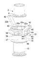
本発明の一実施形態に係る管継手10は、図1及び図2に示すように、第1管状部12、第1管状部12と同軸状に設けられた第2管状部14、及び第1管状部12と第2管状部14とを連結する連結部16を有する継手本体18と、継手本体18の第2管状部14に形成された1対の開口20a、20bに配置され継手本体18に対して枢動可能に設けられた一対の固定用レバー22a、22bと、を備えている。第1管状部12の内周面24よりも大径とされた第2管状部14の内周面26の直径は連結相手となるヘルール管2のヘルールであるフランジ4を受け入れる大きさとされている。当該管継手10は、第2管状部14内にヘルール管2を受け入れた状態で固定用レバー22a、22bを操作することにより、ヘルール管2を連結固定するようになっている。
As shown in FIGS. 1 and 2, a
連結部16には、第1管状部12の内周面24と第2管状部14の内周面26との間において、第1及び第2管状部12、14の軸線Lに対して垂直な平面内で環状に延びる環状段面28が形成されている。この環状段面28にはヘルール管2のフランジ4の係合端面6と密封係合する環状のシール部材30が設定されている。第2管状部14の内周面26において環状段面28と連接する部分には、環状のシール部材係合溝32が形成されていて、シール部材30は、その外周面に形成された環状の係合突部34がシール部材係合溝32に嵌められることにより継手本体18に固定される。
The connecting
図1に示すように、継手本体18の第2管状部14に形成された1対の開口20a、20bは、連結部16に隣接した位置から連結部16から離れる方向に向かって軸線Lと平行に延びる細長い形状を有している。これらの開口20a、20bの両脇には、レバー保持部36が第2管状部14の外周面37から外側に突出するように設けられている。固定用レバー22a、22bはこのレバー保持部36に固定された枢動シャフト38によって、継手本体18に対して枢着されており、図2に示す解放位置と図4に示す連結位置との間で枢動可能となっている。固定用レバー22a、22bは、枢動シャフト38が通される連結用部40と、枢動シャフト38から離れる方向に向かって連結用部40から細く延びる操作部42とを備える。連結用部40には、図4の連結状態においてヘルール管2のフランジ4と係合してフランジ4を環状段面28に向かって押圧する湾曲押圧面44と、湾曲押圧面44に連接し当該固定用レバーが図4に示す連結位置とされたときに、ヘルール管2の外周面8と近接した位置で軸線Lと平行に延びる係合保持面46とが設けられている。
As shown in FIG. 1, the pair of
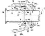
当該管継手10をヘルール管2と連結する際には、まず固定用レバー22a、22bを図2に示す解放位置にして、ヘルール管2を継手本体18の第2管状部14内に挿入する。固定用レバー22a、22bを連結位置に向かって枢動させていくと、図3に示すように湾曲押圧面44がヘルール管2のフランジ4に係合する。湾曲押圧面44はカム状の湾曲を構成していて、固定用レバー22a、22bをさらに枢動させると、ヘルール管2のフランジ4は湾曲押圧面44によって環状段面28に向かって押圧されていく。図4に示すように、固定用レバー22a、22bを、操作部42の内側に設けられた当接面48が継手本体18の第2管状部14の外周面37に当接する位置にまで枢動させて連結位置とすると、環状段面28に固定されているシール部材30が環状段面28とヘルール管2の係合端面6との間で圧縮されて環状段面28と係合端面6との間を密封係合した状態となり連結が完了する。
When connecting the
固定用レバー22a、22bの湾曲押圧面44は、図4の連結状態において、ヘルール管2のフランジ4と係合している位置における法線Nが固定用レバー22a、22bの枢動の中心軸線Cよりも第2管状部14の半径方向を基準として内側を通るような湾曲形状とされている。湾曲押圧面44をこのような形状とすることにより、シール部材30や内圧によってヘルール管2が当該管継手10から離れる方向の力を受けたときに、固定用レバー22a、22bがヘルール管2から受ける力は固定用レバー22a、22bを解放位置とは反対方向に回転させる方向Rの力となる。したがって、ヘルール管2から受ける力によって固定用レバー22a、22bが意図せず解放位置に枢動しヘルール管2が外れてしまうことを防止することができる。また、通常は安全のために内圧が掛かってない状態でヘルール管2との連結を解除するが、仮に圧力が高い状態のまま固定用レバー22a、22bを枢動させてヘルール管2を取り外そうとした場合には、固定用レバー22a、22bを枢動させるのに必要な力が通常よりも大きくなる。それによって作業者は内部に圧力が掛かっていることを認識することができるので、不用意に内部の高圧流体が吹き出したり、ヘルール管2が吹き飛ばされたりするなどの事態を未然に防ぐことが可能になる。また、ヘルール管2の内径や固定用レバー22a、22bとフランジ4との間の摩擦の大きさなどの影響を考慮しつつ法線Nの方向を設定することにより、ある規定値以上の内部圧力が掛かっていている状態においては、通常の作業者の力では固定用レバー22a、22bを操作できないようにすることもできる。
The curved
当該管継手10は、一対の固定用レバー22a、22bを同時に連結位置に枢動させるのではなく、一方の固定用レバー22aを先に連結位置にまで枢動させ、その後に他方の固定用レバー22bを連結位置にまで枢動させるようにすることもできるようになっている。一方の固定用レバー22aのみを連結位置にまで枢動させると、図5に示すように、ヘルール管2のフランジ4は一方の側だけが押圧されてシール部材30が部分的に圧縮され、ヘルール管2は連結位置とされた固定用レバー22aの側にその外周面8が固定用レバー22aの係合保持面46に当接する位置にまで傾く。この状態において他方の固定用レバー22bを連結位置に向かって枢動させると、その湾曲押圧面44がヘルール管2のフランジ4に係合する。図5の状態からさらに固定用レバー22bを連結位置に向かって枢動させることにより、フランジ4は環状段面28に向かって押圧されて、図4に示す連結状態となる。このように固定用レバー22a、22bにヘルール管2の外周面と係合する係合保持面46を設けてヘルール管2の傾き量を一定の範囲内に抑えることで、一方の固定用レバー22aのみを連結位置に枢動させてヘルール管2が傾いてしまった場合でも、フランジ4の位置を他方の固定用レバー22bの湾曲押圧面44と係合可能な範囲内に収めることができる。従って、一対の固定用レバー22a、22bを必ずしも同時に連結位置にまで枢動させるように操作する必要はなく、一つずつ順番に操作した場合でもヘルール管2の連結を正常に完了させることが可能となる。
The pipe joint 10 does not pivot the pair of fixing
上記実施形態においては、一対の固定用レバー22a、22bを備えているが、該一対の固定用レバー22a、22bに加えて追加の固定用レバーをさらに備えるようにしてもよい。
In the above embodiment, the pair of fixing
また、上記実施形態においては、一方の固定用レバー22aのみを連結位置としたときに該一方の固定用レバー22aにヘルール管2の外周面8が当接することでヘルール管2の傾き量を抑えるようにしているが、必ずしも固定用レバー22a、22bが傾いたヘルール管2の外周面8に当接するようにする必要はない。
Further, in the above embodiment, when only one fixing
ヘルール管2;フランジ4;係合端面6;外周面8;管継手10;第1管状部12;第2管状部14;連結部16;継手本体18;開口20a、20b;固定用レバー22a、22b;内周面24;内周面26;環状段面28;シール部材30;シール部材係合溝32;係合突部34;レバー保持部36;外周面37;枢動シャフト38;連結用部40;操作部42;湾曲押圧面44;係合保持面46;当接面48;軸線L;法線N;中心軸線C;方向R;
Claims (2)
第1管状部と、該第1管状部の端部に該第1管状部と同軸状に設けられ該第1管状部よりも大きい内径を有する第2管状部と、該第1管状部と該第2管状部とを連結する連結部であって、該第1管状部の内周面と該第2管状部の内周面との間で該第1及び第2管状部の軸線に対して垂直な平面内で環状に延びる環状段面を有する連結部と、を備える継手本体であって、該第2管状部は、該フランジを受け入れ可能な内径を有しており、直径方向で相互に対向する位置に、該連結部に隣接した位置から該連結部から離れる方向に向かって延びる一対の開口を有している継手本体と、
該開口内にそれぞれ設定され、該第2管状部に枢着されて該軸線と該開口とを通る平面内で連結位置と解放位置との間で枢動可能にされた一対の固定用レバーであって、該連結位置においては該開口から該第2管状部内に入り該フランジを該第2管状部内に固定し、該解放位置においては該第2管状部内から出て、該フランジが該第2管状部に対して該軸線の方向で出入りできるような位置となる連結用部を備えており、該連結用部は、該連結位置において該フランジに係合して該フランジを該環状段面に向けて押圧する湾曲押圧面を有する固定用レバーと、
を備え、
該固定用レバーの該連結用部の該湾曲押圧面は、該固定用レバーが該解放位置から該連結位置に向けて動かされると該フランジと係合し、該固定用レバーが該連結位置に近づくにつれて、該フランジを次第に該環状段面に向けて近づけるように湾曲されており、
該固定用レバーの該連結用部の該湾曲押圧面は、また、該固定用レバーが該連結位置とされたときに該フランジと係合する位置における当該湾曲押圧面の法線が該固定用レバーの該第2管状部に対する枢動の中心軸線よりも該第2管状部の半径方向を基準として内側を通るように形状付けられていることを特徴とする管継手。 A pipe joint for connecting a ferrule pipe having a flange extending radially outward and circumferentially at an end,
A first tubular portion; a second tubular portion provided coaxially with the first tubular portion at an end of the first tubular portion and having a larger inner diameter than the first tubular portion; the first tubular portion; A connecting portion for connecting the second tubular portion with respect to the axes of the first and second tubular portions between the inner peripheral surface of the first tubular portion and the inner peripheral surface of the second tubular portion; A coupling body having an annular step surface extending annularly in a vertical plane, the second tubular portion having an inner diameter capable of receiving the flange and diametrically mutually A joint body having a pair of openings extending in a direction facing away from the connecting portion from a position adjacent to the connecting portion at opposing positions;
A pair of fixing levers set in the opening and pivotally attached to the second tubular portion so as to be pivotable between a connecting position and a releasing position in a plane passing through the axis and the opening. And, in the connecting position, enters the second tubular portion from the opening to fix the flange in the second tubular portion, and in the released position, exits from the second tubular portion, and the flange is the second tubular portion. A connecting portion that is positioned so as to be able to enter and exit in the direction of the axis with respect to the tubular portion; the connecting portion engages with the flange at the connecting position so that the flange is brought into contact with the annular step surface; A fixing lever having a curved pressing surface to be pressed toward,
With
The curved pressing surface of the connecting portion of the fixing lever engages with the flange when the fixing lever is moved from the release position toward the connecting position, and the fixing lever is moved to the connecting position. As it approaches, the flange is gradually curved toward the annular step surface,
The curved pressing surface of the connecting portion of the fixing lever is also configured such that a normal line of the curved pressing surface at a position where the fixing lever engages with the flange when the fixing lever is set to the connecting position. A pipe joint characterized in that it is shaped so as to pass inward with respect to the radial direction of the second tubular portion relative to the central axis of the pivot of the lever with respect to the second tubular portion.
Priority Applications (1)
| Application Number | Priority Date | Filing Date | Title |
|---|---|---|---|
| JP2013240579A JP2015102103A (en) | 2013-11-21 | 2013-11-21 | Pipe joint |
Applications Claiming Priority (1)
| Application Number | Priority Date | Filing Date | Title |
|---|---|---|---|
| JP2013240579A JP2015102103A (en) | 2013-11-21 | 2013-11-21 | Pipe joint |
Publications (1)
| Publication Number | Publication Date |
|---|---|
| JP2015102103A true JP2015102103A (en) | 2015-06-04 |
Family
ID=53377988
Family Applications (1)
| Application Number | Title | Priority Date | Filing Date |
|---|---|---|---|
| JP2013240579A Pending JP2015102103A (en) | 2013-11-21 | 2013-11-21 | Pipe joint |
Country Status (1)
| Country | Link |
|---|---|
| JP (1) | JP2015102103A (en) |
Cited By (2)
| Publication number | Priority date | Publication date | Assignee | Title |
|---|---|---|---|---|
| KR20220099035A (en) * | 2021-01-05 | 2022-07-12 | 울산대학교 산학협력단 | quick coupling with fastening handle |
| JP2022141420A (en) * | 2021-03-15 | 2022-09-29 | ヤンマーeスター株式会社 | Pressure wave generation device |
Citations (7)
| Publication number | Priority date | Publication date | Assignee | Title |
|---|---|---|---|---|
| GB299632A (en) * | 1927-12-14 | 1928-11-01 | George Dean | Improvements in and relating to pipe and similar joints |
| US4938511A (en) * | 1988-06-17 | 1990-07-03 | Econt Corporation Limited | Tube coupling |
| EP0486432A1 (en) * | 1990-11-15 | 1992-05-20 | Wbt Wirtschaftsberatungs Trust Reg | Outlet device for a hose transporting concrete, mortar, floor cement or the like |
| JP3314009B2 (en) * | 1997-07-09 | 2002-08-12 | 日東工器株式会社 | Pipe fittings |
| US20030151252A1 (en) * | 2002-02-12 | 2003-08-14 | Dole Douglas R. | Self-locking roller cam for hose and pipe coupling |
| US20080023960A1 (en) * | 2006-07-28 | 2008-01-31 | George Carmichael | Sanitary quick connector |
| US20110057439A1 (en) * | 2008-05-09 | 2011-03-10 | Kariniemi Thomas E | High pressure cam and groove connector |
-
2013
- 2013-11-21 JP JP2013240579A patent/JP2015102103A/en active Pending
Patent Citations (7)
| Publication number | Priority date | Publication date | Assignee | Title |
|---|---|---|---|---|
| GB299632A (en) * | 1927-12-14 | 1928-11-01 | George Dean | Improvements in and relating to pipe and similar joints |
| US4938511A (en) * | 1988-06-17 | 1990-07-03 | Econt Corporation Limited | Tube coupling |
| EP0486432A1 (en) * | 1990-11-15 | 1992-05-20 | Wbt Wirtschaftsberatungs Trust Reg | Outlet device for a hose transporting concrete, mortar, floor cement or the like |
| JP3314009B2 (en) * | 1997-07-09 | 2002-08-12 | 日東工器株式会社 | Pipe fittings |
| US20030151252A1 (en) * | 2002-02-12 | 2003-08-14 | Dole Douglas R. | Self-locking roller cam for hose and pipe coupling |
| US20080023960A1 (en) * | 2006-07-28 | 2008-01-31 | George Carmichael | Sanitary quick connector |
| US20110057439A1 (en) * | 2008-05-09 | 2011-03-10 | Kariniemi Thomas E | High pressure cam and groove connector |
Cited By (4)
| Publication number | Priority date | Publication date | Assignee | Title |
|---|---|---|---|---|
| KR20220099035A (en) * | 2021-01-05 | 2022-07-12 | 울산대학교 산학협력단 | quick coupling with fastening handle |
| KR102497312B1 (en) * | 2021-01-05 | 2023-02-07 | 울산대학교 산학협력단 | quick coupling with fastening handle |
| JP2022141420A (en) * | 2021-03-15 | 2022-09-29 | ヤンマーeスター株式会社 | Pressure wave generation device |
| JP7634871B2 (en) | 2021-03-15 | 2025-02-25 | ヤンマーeスター株式会社 | Pressure Wave Generator |
Similar Documents
| Publication | Publication Date | Title |
|---|---|---|
| CN104937321B (en) | Emergency release coupling | |
| KR101575896B1 (en) | A connecting device for piping works | |
| JP2015172437A (en) | Pressing jaw, method for producing non-detachable pipe joint, fitting, and system comprising pressing jaw and fitting | |
| KR101756526B1 (en) | Pipe coupling apparatus | |
| KR101755002B1 (en) | One touch type pipe connector | |
| JP7142557B2 (en) | joint | |
| JP6853351B2 (en) | Fittings and fitting assemblies and how to manufacture fittings | |
| JP2010196782A5 (en) | ||
| WO2018159201A1 (en) | Piping joint | |
| CN1894532B (en) | Insertable and locking fittings | |
| CN110114608A (en) | Push-in type is linked and packed component and device | |
| JP2015102103A (en) | Pipe joint | |
| CN110014391A (en) | The tool and method of sealing element is installed | |
| JP2003021287A (en) | Spigot joint | |
| JP6039537B2 (en) | Pipe fitting | |
| JP5091849B2 (en) | Pipe fitting | |
| US7028982B2 (en) | Coupling member for a pipe coupling | |
| KR101821229B1 (en) | Fixing device for piping fitting | |
| US9939091B2 (en) | Modular pipe clamp | |
| JP7017441B2 (en) | Pipe fittings | |
| KR101515841B1 (en) | Conduit Connecting Apparatus Having a Bush | |
| KR101854531B1 (en) | Apparatus for branching | |
| KR101843005B1 (en) | Quick coupler | |
| JP4781164B2 (en) | Connection method of joint body | |
| JP2003028371A (en) | Pipe joint |
Legal Events
| Date | Code | Title | Description |
|---|---|---|---|
| A621 | Written request for application examination |
Free format text: JAPANESE INTERMEDIATE CODE: A621 Effective date: 20150917 |
|
| A977 | Report on retrieval |
Free format text: JAPANESE INTERMEDIATE CODE: A971007 Effective date: 20160719 |
|
| A131 | Notification of reasons for refusal |
Free format text: JAPANESE INTERMEDIATE CODE: A131 Effective date: 20160726 |
|
| A02 | Decision of refusal |
Free format text: JAPANESE INTERMEDIATE CODE: A02 Effective date: 20170131 |