JP2015102116A - 密封装置 - Google Patents
密封装置 Download PDFInfo
- Publication number
- JP2015102116A JP2015102116A JP2013241572A JP2013241572A JP2015102116A JP 2015102116 A JP2015102116 A JP 2015102116A JP 2013241572 A JP2013241572 A JP 2013241572A JP 2013241572 A JP2013241572 A JP 2013241572A JP 2015102116 A JP2015102116 A JP 2015102116A
- Authority
- JP
- Japan
- Prior art keywords
- piston seal
- annular
- cancel plate
- cylindrical portion
- inner peripheral
- Prior art date
- Legal status (The legal status is an assumption and is not a legal conclusion. Google has not performed a legal analysis and makes no representation as to the accuracy of the status listed.)
- Granted
Links
- 238000007789 sealing Methods 0.000 title claims abstract description 23
- 230000002093 peripheral effect Effects 0.000 claims abstract description 51
- 239000012530 fluid Substances 0.000 claims abstract description 8
- 230000005540 biological transmission Effects 0.000 claims description 21
- 230000005489 elastic deformation Effects 0.000 claims description 14
- 238000003825 pressing Methods 0.000 claims description 8
- 239000013013 elastic material Substances 0.000 claims description 2
- 239000003921 oil Substances 0.000 description 11
- 239000010720 hydraulic oil Substances 0.000 description 9
- 230000007246 mechanism Effects 0.000 description 6
- 239000013585 weight reducing agent Substances 0.000 description 4
- 239000002184 metal Substances 0.000 description 3
- 238000000034 method Methods 0.000 description 3
- 229920003051 synthetic elastomer Polymers 0.000 description 3
- 239000005061 synthetic rubber Substances 0.000 description 3
- 229910000746 Structural steel Inorganic materials 0.000 description 2
- 238000005520 cutting process Methods 0.000 description 2
- 229920001971 elastomer Polymers 0.000 description 2
- 238000005242 forging Methods 0.000 description 2
- 238000012986 modification Methods 0.000 description 2
- 230000004048 modification Effects 0.000 description 2
- 239000005060 rubber Substances 0.000 description 2
- 229920001875 Ebonite Polymers 0.000 description 1
- 229910000831 Steel Inorganic materials 0.000 description 1
- 230000002159 abnormal effect Effects 0.000 description 1
- 230000008901 benefit Effects 0.000 description 1
- 239000000470 constituent Substances 0.000 description 1
- 230000008878 coupling Effects 0.000 description 1
- 238000010168 coupling process Methods 0.000 description 1
- 238000005859 coupling reaction Methods 0.000 description 1
- 239000000463 material Substances 0.000 description 1
- 238000000465 moulding Methods 0.000 description 1
- 230000010355 oscillation Effects 0.000 description 1
- 238000004080 punching Methods 0.000 description 1
- 239000010959 steel Substances 0.000 description 1
Images
Classifications
-
- F—MECHANICAL ENGINEERING; LIGHTING; HEATING; WEAPONS; BLASTING
- F16—ENGINEERING ELEMENTS AND UNITS; GENERAL MEASURES FOR PRODUCING AND MAINTAINING EFFECTIVE FUNCTIONING OF MACHINES OR INSTALLATIONS; THERMAL INSULATION IN GENERAL
- F16D—COUPLINGS FOR TRANSMITTING ROTATION; CLUTCHES; BRAKES
- F16D25/00—Fluid-actuated clutches
- F16D25/06—Fluid-actuated clutches in which the fluid actuates a piston incorporated in, i.e. rotating with the clutch
- F16D25/062—Fluid-actuated clutches in which the fluid actuates a piston incorporated in, i.e. rotating with the clutch the clutch having friction surfaces
- F16D25/063—Fluid-actuated clutches in which the fluid actuates a piston incorporated in, i.e. rotating with the clutch the clutch having friction surfaces with clutch members exclusively moving axially
- F16D25/0635—Fluid-actuated clutches in which the fluid actuates a piston incorporated in, i.e. rotating with the clutch the clutch having friction surfaces with clutch members exclusively moving axially with flat friction surfaces, e.g. discs
- F16D25/0638—Fluid-actuated clutches in which the fluid actuates a piston incorporated in, i.e. rotating with the clutch the clutch having friction surfaces with clutch members exclusively moving axially with flat friction surfaces, e.g. discs with more than two discs, e.g. multiple lamellae
-
- F—MECHANICAL ENGINEERING; LIGHTING; HEATING; WEAPONS; BLASTING
- F16—ENGINEERING ELEMENTS AND UNITS; GENERAL MEASURES FOR PRODUCING AND MAINTAINING EFFECTIVE FUNCTIONING OF MACHINES OR INSTALLATIONS; THERMAL INSULATION IN GENERAL
- F16D—COUPLINGS FOR TRANSMITTING ROTATION; CLUTCHES; BRAKES
- F16D25/00—Fluid-actuated clutches
- F16D25/12—Details not specific to one of the before-mentioned types
-
- F—MECHANICAL ENGINEERING; LIGHTING; HEATING; WEAPONS; BLASTING
- F16—ENGINEERING ELEMENTS AND UNITS; GENERAL MEASURES FOR PRODUCING AND MAINTAINING EFFECTIVE FUNCTIONING OF MACHINES OR INSTALLATIONS; THERMAL INSULATION IN GENERAL
- F16D—COUPLINGS FOR TRANSMITTING ROTATION; CLUTCHES; BRAKES
- F16D2300/00—Special features for couplings or clutches
- F16D2300/08—Details or arrangements of sealings not provided for in group F16D3/84
Landscapes
- Engineering & Computer Science (AREA)
- General Engineering & Computer Science (AREA)
- Mechanical Engineering (AREA)
- Hydraulic Clutches, Magnetic Clutches, Fluid Clutches, And Fluid Joints (AREA)
Abstract
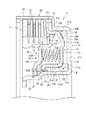
【解決手段】流体圧力により軸方向一方側へ移動してディスククラッチCのディスクC1を押圧する環状のピストンシール11と、ピストンシール11に対向させた状態でピストンシール11の軸方向一方側に配置された環状のキャンセルプレート12とを備え、ピストンシール11が、環状部11aと、ディスクC1を押圧する外円筒部11cと、内円筒部11bとを有し、キャンセルプレート12の内周側の側面と内円筒部11bの先端部との間に、外円筒部11cが軸方向一方側のストロークエンドに到達した状態でキャンセルプレート12の内周側の側面と内円筒部11bの先端部とによって挟み込んで内円筒部11bが軸方向一方側へ移動するのを流体圧力に抗して停止させることにより、ピストンシール11の過度の弾性変形を防止するストッパ部材32を備えている。
【選択図】 図1
Description
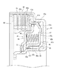
密封装置41は、ハウジング42との間で油圧室46を構成しかつ油圧によりハウジング42内を軸方向一方側へ移動してディスククラッチ44のディスク44aを押圧することによりディスククラッチ44を動力伝達モードとする環状のボンデッドピストンシール47と、このボンデッドピストンシール47に対向させた状態で軸方向一方側に配置された環状のキャンセルプレート48と、ボンデッドピストンシール47及び前記キャンセルプレート48との間に介装され両者を軸方向に離間する方向に付勢するリターンスプリング49と、を備えている。
ところで、前記のように、従来では、ボンデッドピストンシール47の内向き折曲部47fとキャンセルプレート48の内周部との間には、軸方向に関して、外円筒部47cが軸方向一方側のストロークエンドに到達した状態でも内向き折曲部47fがキャンセルプレート48の内周部と当接しないような大きな隙間51が形成されているので、ボンデッドピストンシール47の大きな弾性変形が許容されていた。そのため、上記モーメントM1により、軽量化のため厚みが薄くされているボンデッドピストンシール47には、その内周部の内向き折曲部47fがキャンセルプレート48の内周部に向かって軸方向に移動する弾性変形が生じる。又、これと共に、ボンデッドピストンシール47内部には応力が発生するが、ボンデッドピストンシール47における、断面形状の変化部である各屈曲部47d,47eでは、局所的に応力が増大する応力集中が起きる。
本発明はこのような事情に鑑みてなされたものであり、ピストンシールの破損に繋がる弾性変形を防止することができる密封装置を提供することを目的とする。
このように、ストッパ部材により、ピストンシールの内円筒部の先端部の移動が抑制されるので、前記モーメントに起因するピストンシールの破損に繋がる過度の(大きな)弾性変形が防止される。
この構成によれば、ピストンシールがストッパに当接した際の衝撃は、ストッパの弾性変形により、緩和乃至は吸収され、上記衝撃による異音の発生を抑制できる。
図1中、動力伝達機構1は、遊星ギヤセット(図示せず)に対する動力の伝達を断続するためのディスククラッチCと、このディスククラッチCを作動させるためのクラッチピストンの機能を備えた密封装置10と、これらを内部に収納しているハウジング20とを備えている。
ハウジング20は、例えば、熱間圧延鋼板等を用いて板金プレス成型等によって軸方向一方側に開口する断面凹型に形成された環状の部材であり、内部に環状の密封装置10が挿入、配置されたシリンダ部21と、このシリンダ部21における外周壁21aの軸方向一方側の端部から延びてディスククラッチCを収納している外側円筒部22とを備えている。
第1・第2シール部材14,31は、ボンデッドピストンシール11とシリンダ部21との間を密封することで、第1油室R1を密封している。
大径環状部12aの外周端部には、キャンセルプレート12と、ボンデッドピストンシール11との間を密封する環状の第3シール部材16が固着されている。第3シール部材16は、合成ゴム等の弾性部材を用いて大径環状部12aの外周端部に加硫接着されており、外周側へ延びることでボンデッドピストンシール11の外円筒部11cの内周面に摺接するシールリップ16aを有している。
第3シール部材16は、キャンセルプレート12とボンデッドピストンシール11との間を密封することで、第2油室R2を密封している。
ディスククラッチCにより、動力伝達を行う際には、第1油室R1に作動油を供給し、ボンデッドピストンシール11を軸方向一方側へ移動させて、その外周部の外向き折曲部11iによりディスククラッチCのディスクC1を押圧して、ディスククラッチCを動力伝達モードとする。
この停止より前に、ボンデッドピストンシール11の外向き折曲部11iが、そのディスククラッチCの押圧ストロークで、ストロークエンド(最終押圧位置)に到達するようであれば、この到達から上記停止までの間に、ボンデッドピストンシール11には、作動油の油圧により、ボンデッドピストンシール11を外向き折曲部11iを中心として軸方向一方側に押圧するモーメントMが作用する。
その結果、ボンデッドピストンシール11における、応力集中が起きている各屈曲部11d,11eに生じる応力が従来のように増大せず、これにより、上記弾性変形の繰り返しによって屈曲部11d,11eにクラックが発生することを抑制できて、ボンデッドピストンシール11の破損(疲労破壊)を防止できる。
Claims (2)
- 流体圧力により軸方向一方側へ移動してディスククラッチのディスクを押圧することにより、前記ディスククラッチを動力伝達モードとする環状のピストンシールと、このピストンシールに対向させた状態で当該ピストンシールの軸方向一方側に配置された環状のキャンセルプレートとを備える密封装置であって、
前記ピストンシールが、径方向に延びる環状部と、この環状部の外周側から軸方向一方側に延びて前記ディスクを押圧する外円筒部と、前記環状部の内周側から軸方向一方側に延びる内円筒部とを有し、
前記キャンセルプレートの内周側の側面と前記内円筒部の先端部との間に、前記外円筒部が軸方向一方側のストロークエンドに到達した状態で前記キャンセルプレートの内周側の側面と前記内円筒部の先端部とによって挟み込んで当該内円筒部が軸方向一方側へ移動するのを前記流体圧力に抗して停止させることにより、前記ピストンシールの過度の弾性変形を防止するストッパ部材を備えることを特徴とする密封装置。 - 前記ストッパが弾性材料により形成された請求項1記載の密封装置。
Priority Applications (1)
| Application Number | Priority Date | Filing Date | Title |
|---|---|---|---|
| JP2013241572A JP6279293B2 (ja) | 2013-11-22 | 2013-11-22 | 密封装置 |
Applications Claiming Priority (1)
| Application Number | Priority Date | Filing Date | Title |
|---|---|---|---|
| JP2013241572A JP6279293B2 (ja) | 2013-11-22 | 2013-11-22 | 密封装置 |
Publications (2)
| Publication Number | Publication Date |
|---|---|
| JP2015102116A true JP2015102116A (ja) | 2015-06-04 |
| JP6279293B2 JP6279293B2 (ja) | 2018-02-14 |
Family
ID=53377995
Family Applications (1)
| Application Number | Title | Priority Date | Filing Date |
|---|---|---|---|
| JP2013241572A Active JP6279293B2 (ja) | 2013-11-22 | 2013-11-22 | 密封装置 |
Country Status (1)
| Country | Link |
|---|---|
| JP (1) | JP6279293B2 (ja) |
Cited By (1)
| Publication number | Priority date | Publication date | Assignee | Title |
|---|---|---|---|---|
| CN115443386A (zh) * | 2020-05-01 | 2022-12-06 | Nok株式会社 | 离合器活塞机构的构成要素的识别结构以及离合器活塞机构的构成要素的识别方法 |
Citations (4)
| Publication number | Priority date | Publication date | Assignee | Title |
|---|---|---|---|---|
| JPH09303423A (ja) * | 1996-05-09 | 1997-11-25 | Nok Corp | 密封装置 |
| JP2007024167A (ja) * | 2005-07-15 | 2007-02-01 | Mazda Motor Corp | 変速機のクラッチ構造 |
| JP2008256057A (ja) * | 2007-04-04 | 2008-10-23 | Nok Corp | 自動変速機用ピストン |
| JP2010270833A (ja) * | 2009-05-21 | 2010-12-02 | Koyo Sealing Techno Co Ltd | 密封装置 |
-
2013
- 2013-11-22 JP JP2013241572A patent/JP6279293B2/ja active Active
Patent Citations (4)
| Publication number | Priority date | Publication date | Assignee | Title |
|---|---|---|---|---|
| JPH09303423A (ja) * | 1996-05-09 | 1997-11-25 | Nok Corp | 密封装置 |
| JP2007024167A (ja) * | 2005-07-15 | 2007-02-01 | Mazda Motor Corp | 変速機のクラッチ構造 |
| JP2008256057A (ja) * | 2007-04-04 | 2008-10-23 | Nok Corp | 自動変速機用ピストン |
| JP2010270833A (ja) * | 2009-05-21 | 2010-12-02 | Koyo Sealing Techno Co Ltd | 密封装置 |
Cited By (1)
| Publication number | Priority date | Publication date | Assignee | Title |
|---|---|---|---|---|
| CN115443386A (zh) * | 2020-05-01 | 2022-12-06 | Nok株式会社 | 离合器活塞机构的构成要素的识别结构以及离合器活塞机构的构成要素的识别方法 |
Also Published As
| Publication number | Publication date |
|---|---|
| JP6279293B2 (ja) | 2018-02-14 |
Similar Documents
| Publication | Publication Date | Title |
|---|---|---|
| CN101523072A (zh) | 密封件一体成型活塞 | |
| JP7141208B2 (ja) | 密封装置 | |
| JP6279293B2 (ja) | 密封装置 | |
| JP6117000B2 (ja) | ピストン一体シール | |
| JP6576745B2 (ja) | 密封装置及びこれに用いるキャンセルプレートの製造方法 | |
| JP6193074B2 (ja) | クラッチピストン及びその製造方法 | |
| JP2011163438A (ja) | 往復動用シールリング | |
| JP5394131B2 (ja) | 密封装置の製造方法 | |
| JP2010190391A (ja) | 自動変速機用ピストンシール | |
| JP4972515B2 (ja) | 流体式変速機のクラッチピストン | |
| JP7636275B2 (ja) | 密封装置 | |
| JP2005265073A (ja) | ピストン装置 | |
| JP2008256056A (ja) | 自動変速機用ピストン | |
| JP2006138398A (ja) | クラッチピストン | |
| CN113677906A (zh) | 液压促动器的密封装置 | |
| JP4843405B2 (ja) | 密封装置 | |
| JP7678717B2 (ja) | 油圧アクチュエータの密封装置 | |
| CN1938536A (zh) | 密封装置 | |
| JP2009058053A (ja) | 自動変速機用ピストン | |
| JP2020118217A (ja) | 密封装置 | |
| JP2022076048A (ja) | 密封装置 | |
| JP2008256057A (ja) | 自動変速機用ピストン | |
| JP2006144901A (ja) | 往復動シール | |
| JP2005325995A (ja) | ピストン | |
| JP2009041707A (ja) | キャンセルプレート |
Legal Events
| Date | Code | Title | Description |
|---|---|---|---|
| A621 | Written request for application examination |
Free format text: JAPANESE INTERMEDIATE CODE: A621 Effective date: 20160815 |
|
| A977 | Report on retrieval |
Free format text: JAPANESE INTERMEDIATE CODE: A971007 Effective date: 20170412 |
|
| A131 | Notification of reasons for refusal |
Free format text: JAPANESE INTERMEDIATE CODE: A131 Effective date: 20170530 |
|
| A521 | Request for written amendment filed |
Free format text: JAPANESE INTERMEDIATE CODE: A523 Effective date: 20170713 |
|
| TRDD | Decision of grant or rejection written | ||
| A01 | Written decision to grant a patent or to grant a registration (utility model) |
Free format text: JAPANESE INTERMEDIATE CODE: A01 Effective date: 20180109 |
|
| A61 | First payment of annual fees (during grant procedure) |
Free format text: JAPANESE INTERMEDIATE CODE: A61 Effective date: 20180117 |
|
| R150 | Certificate of patent or registration of utility model |
Ref document number: 6279293 Country of ref document: JP Free format text: JAPANESE INTERMEDIATE CODE: R150 |
|
| R250 | Receipt of annual fees |
Free format text: JAPANESE INTERMEDIATE CODE: R250 |
|
| R250 | Receipt of annual fees |
Free format text: JAPANESE INTERMEDIATE CODE: R250 |