JP2015102131A - Split type cage for tapered roller bearing, and tapered roller bearing - Google Patents
Split type cage for tapered roller bearing, and tapered roller bearing Download PDFInfo
- Publication number
- JP2015102131A JP2015102131A JP2013242022A JP2013242022A JP2015102131A JP 2015102131 A JP2015102131 A JP 2015102131A JP 2013242022 A JP2013242022 A JP 2013242022A JP 2013242022 A JP2013242022 A JP 2013242022A JP 2015102131 A JP2015102131 A JP 2015102131A
- Authority
- JP
- Japan
- Prior art keywords
- cage
- tapered roller
- roller bearing
- split type
- segment
- Prior art date
- Legal status (The legal status is an assumption and is not a legal conclusion. Google has not performed a legal analysis and makes no representation as to the accuracy of the status listed.)
- Pending
Links
Images

Classifications
-
- F—MECHANICAL ENGINEERING; LIGHTING; HEATING; WEAPONS; BLASTING
- F16—ENGINEERING ELEMENTS AND UNITS; GENERAL MEASURES FOR PRODUCING AND MAINTAINING EFFECTIVE FUNCTIONING OF MACHINES OR INSTALLATIONS; THERMAL INSULATION IN GENERAL
- F16C—SHAFTS; FLEXIBLE SHAFTS; ELEMENTS OR CRANKSHAFT MECHANISMS; ROTARY BODIES OTHER THAN GEARING ELEMENTS; BEARINGS
- F16C19/00—Bearings with rolling contact, for exclusively rotary movement
- F16C19/22—Bearings with rolling contact, for exclusively rotary movement with bearing rollers essentially of the same size in one or more circular rows, e.g. needle bearings
- F16C19/34—Bearings with rolling contact, for exclusively rotary movement with bearing rollers essentially of the same size in one or more circular rows, e.g. needle bearings for both radial and axial load
- F16C19/36—Bearings with rolling contact, for exclusively rotary movement with bearing rollers essentially of the same size in one or more circular rows, e.g. needle bearings for both radial and axial load with a single row of rollers
- F16C19/364—Bearings with rolling contact, for exclusively rotary movement with bearing rollers essentially of the same size in one or more circular rows, e.g. needle bearings for both radial and axial load with a single row of rollers with tapered rollers, i.e. rollers having essentially the shape of a truncated cone
-
- F—MECHANICAL ENGINEERING; LIGHTING; HEATING; WEAPONS; BLASTING
- F16—ENGINEERING ELEMENTS AND UNITS; GENERAL MEASURES FOR PRODUCING AND MAINTAINING EFFECTIVE FUNCTIONING OF MACHINES OR INSTALLATIONS; THERMAL INSULATION IN GENERAL
- F16C—SHAFTS; FLEXIBLE SHAFTS; ELEMENTS OR CRANKSHAFT MECHANISMS; ROTARY BODIES OTHER THAN GEARING ELEMENTS; BEARINGS
- F16C33/00—Parts of bearings; Special methods for making bearings or parts thereof
- F16C33/30—Parts of ball or roller bearings
- F16C33/46—Cages for rollers or needles
- F16C33/51—Cages for rollers or needles formed of unconnected members
-
- F—MECHANICAL ENGINEERING; LIGHTING; HEATING; WEAPONS; BLASTING
- F16—ENGINEERING ELEMENTS AND UNITS; GENERAL MEASURES FOR PRODUCING AND MAINTAINING EFFECTIVE FUNCTIONING OF MACHINES OR INSTALLATIONS; THERMAL INSULATION IN GENERAL
- F16C—SHAFTS; FLEXIBLE SHAFTS; ELEMENTS OR CRANKSHAFT MECHANISMS; ROTARY BODIES OTHER THAN GEARING ELEMENTS; BEARINGS
- F16C2360/00—Engines or pumps
- F16C2360/31—Wind motors
Landscapes
- Engineering & Computer Science (AREA)
- General Engineering & Computer Science (AREA)
- Mechanical Engineering (AREA)
- Rolling Contact Bearings (AREA)
Abstract
Description
本発明は、複数の保持器セグメントを環状に配列した円すいころ軸受用の分割型保持器、及び円すいころ軸受に関する。 The present invention relates to a split cage for a tapered roller bearing in which a plurality of cage segments are arranged in an annular shape, and a tapered roller bearing.
従来、水平軸プロペラ式の風力発電装置においては、ブレードを取り付ける主軸を回転自在に支持するために、転がり軸受が用いられている。近年、風力発電装置の大型化に伴って、主軸の直径が数メートルを超えることもあり、このような大型の主軸を支持するために転がり軸受も大型化している。大型の転がり軸受に用いられる保持器として、合成樹脂製の保持器が用いられる場合がある。この合成樹脂製の保持器は、溶接で組み立てる金属製の保持器に較べて、軽量であるとともに精度も確保し易いという利点がある。しかし、直径の大きい合成樹脂製の保持器を射出成形で一体成形することは困難である。そこで、転動体を収容する複数の保持器セグメントを環状に配列することによって構成された分割型保持器が用いられている(例えば、特許文献1参照)。 Conventionally, in a horizontal axis propeller-type wind power generator, a rolling bearing is used to rotatably support a main shaft to which a blade is attached. In recent years, with the increase in the size of wind power generators, the diameter of the main shaft may exceed several meters, and the rolling bearing is also increased in size to support such a large main shaft. As a cage used for a large-sized rolling bearing, a synthetic resin cage may be used. This cage made of synthetic resin is advantageous in that it is lightweight and easy to ensure accuracy compared to a metal cage assembled by welding. However, it is difficult to integrally mold a cage made of a synthetic resin having a large diameter by injection molding. In view of this, a split type retainer configured by annularly arranging a plurality of retainer segments that accommodate rolling elements is used (see, for example, Patent Document 1).
特許文献1に記載の保持器セグメントは、軸方向に所定間隔離して対向させた一対の第1,第2リム部と、この第1,第2リム部の間に架設した複数の柱部とを有しており、隣り合う柱部と第1,第2リム部とによって囲まれる空間を、転動体としての円すいころを収容するポケットとしている。特許文献1に記載の保持器セグメントは、5個の柱部を周方向に並べて備えており、各柱部の間に形成された4個のポケットにそれぞれ円すいころが収容されている。
The cage segment described in
円すいころ軸受は、アキシアル荷重が付与されていない状態では、軸からのラジアル荷重を受ける負荷圏とそれ以外の反負荷圏とが存在し、各保持器セグメント及び円すいころは、軸の回転に伴って負荷圏と反負荷圏との間を順次移動する。そして、例えば、円すいころ軸受の下部域がラジアル荷重の負荷圏で上部域が反負荷圏である場合、負荷圏から反負荷圏への保持器セグメントの移動は、負荷圏側の保持器セグメントが反負荷圏側の保持器セグメントを押し上げることによってなされ、反負荷圏の最上部を過ぎると保持器セグメントは自重によって負荷圏側へ向けて落下する。 Tapered roller bearings have a load zone that receives a radial load from the shaft and other anti-load zones when axial load is not applied.Each cage segment and tapered roller is accompanied by the rotation of the shaft. Move sequentially between the load zone and the anti-load zone. And, for example, when the lower area of the tapered roller bearing is a load area of radial load and the upper area is an anti-load area, the cage segment on the load area side moves from the load area to the anti-load area. This is done by pushing up the cage segment on the anti-load zone side, and after passing through the top of the anti-load zone, the cage segment falls toward the load zone side by its own weight.
しかしながら、特許文献1記載の保持器セグメントは、4個の円すいころを収容することによって重量も大きくなるため、負荷圏側へ向けて落下したときに、その下側に配置された他の保持器セグメントに強く衝突し、その衝撃で損傷してしまう可能性が高くなる。
However, since the cage segment described in
一方、このような衝撃を小さくするために、各保持器セグメントに収容する円すいころの数を少なくし(例えば1個)、個々の重量を小さくすることも考えられる。
しかしながら、この場合も、例えば図10に示されるように、円すいころ軸受10に供給されたグリースの表面張力によって、隣接する複数の保持器セグメント20Aが互いに接着してしまうと、これらがまとまって矢印X方向に落下して下側の保持器セグメント20Bに衝突し、その結果、衝撃を小さくすることができなくなる。
On the other hand, in order to reduce such an impact, it is conceivable to reduce the number of tapered rollers accommodated in each cage segment (for example, one) and reduce the individual weight.
However, in this case as well, for example, as shown in FIG. 10, if the
本発明は、以上のような実情に鑑みてなされたものであり、周方向に隣接する保持器セグメント同士がグリースの表面張力によって接着してしまうのを防止し、保持器セグメントの衝突による衝撃を緩和することができる円すいころ軸受用の分割型保持器、並びに円すいころ軸受を提供することを目的とする。 The present invention has been made in view of the circumstances as described above, and prevents the cage segments adjacent in the circumferential direction from adhering to each other due to the surface tension of the grease. An object of the present invention is to provide a split cage for a tapered roller bearing that can be relaxed, and a tapered roller bearing.
本発明は、円すいころを収容する複数の保持器セグメントを周方向に沿って環状に配列した円すいころ軸受用の分割型保持器であって、前記各保持器セグメントは、周方向に隣接する他の保持器セグメントに対向する対向面を有し、互いに対向する対向面の少なくとも一方は、他方に対してその一部において当接可能な構造を備えている。 The present invention is a split-type cage for tapered roller bearings in which a plurality of cage segments for accommodating tapered rollers are arranged in an annular shape along the circumferential direction, and each of the cage segments is adjacent to the circumferential direction. The retainer segments have a facing surface, and at least one of the facing surfaces facing each other has a structure that can abut against the other at a part thereof.
上記構成によれば、周方向に隣接する保持器セグメントの、互いに対向する対向面の少なくとも一方は、他方に対してその一部において当接可能な構造を具備しているので、両対向面同士が全面で接触することがなく、グリースの表面張力で接着してしまうこともほとんどない。そのため、ラジアル荷重の反負荷圏において複数の保持器セグメントがまとまって落下してしまうのを防止することができ、保持器セグメントの衝突による衝撃を緩和することができる。 According to the above configuration, at least one of the opposing surfaces of the cage segments adjacent to each other in the circumferential direction has a structure that can abut against the other part of the opposing surfaces. Are not in contact with the entire surface, and are hardly bonded by the surface tension of grease. For this reason, it is possible to prevent the plurality of cage segments from dropping together in the anti-load zone of the radial load, and to reduce the impact caused by the collision of the cage segments.
前記一方の対向面は、前記他方の対向面に向けて突出し、その先端が前記他方の対向面に当接可能とされた突起部を備えていることが好ましい。
このような構成によって、前記一方の対向面が前記他方の対向面に対してその一部において当接可能な構造を、容易に実現することができる。
It is preferable that the one opposing surface includes a protrusion that protrudes toward the other opposing surface and that has a tip that can contact the other opposing surface.
With such a configuration, it is possible to easily realize a structure in which the one facing surface can abut against the other facing surface at a part thereof.
前記突起部は、前記他方の対向面に点接触又は線接触することが好ましい。
このような構成によって、互いに対向する対向面同士の接触面積を可及的に小さくし、グリースの表面張力による接着をより確実に防止することができる。
It is preferable that the protrusion is in point contact or line contact with the other facing surface.
With such a configuration, the contact area between the opposing surfaces facing each other can be made as small as possible, and adhesion due to the surface tension of the grease can be more reliably prevented.
前記各保持器セグメントは、周方向に並べて配置された複数の柱部と、この柱部の軸方向の端部同士を連結するリム部とを有しており、前記突起部は、軸方向に関して前記リム部の厚さの範囲に重複して形成されていることが好ましい。
このような構成によって、突起部が他方の対向面に当接したときの、柱部にかかる負担を軽減することができ、当該柱部の損傷を抑制することができる。
Each of the cage segments has a plurality of pillars arranged side by side in the circumferential direction, and a rim part that connects axial ends of the pillars, and the protrusions are related to the axial direction. Preferably, the rim portion is formed so as to overlap the thickness range.
With such a configuration, it is possible to reduce a burden on the column portion when the protruding portion is in contact with the other facing surface, and it is possible to suppress damage to the column portion.
前記各保持器セグメントは、1個の円すいころを収容する1つのポケットを有していることが好ましい。
このような構成によって、各保持器セグメントを軽量化し、他の保持器セグメントに衝突したときの衝撃を好適に緩和することができる。
Each of the cage segments preferably has one pocket for accommodating one tapered roller.
With such a configuration, each cage segment can be reduced in weight, and the impact when colliding with another cage segment can be suitably mitigated.
本発明の円すいころ軸受は、内輪軌道面を有する内輪と、この内輪の径方向外方に配置され、外輪軌道面を有する外輪と、前記内輪軌道面及び前記外輪軌道面の間に転動可能に配置された複数の円すいころと、複数の円すいころの間隔を保持する上記の分割型保持器と、を備えている。 The tapered roller bearing of the present invention is capable of rolling between an inner ring having an inner ring raceway surface, an outer ring having an outer ring raceway surface disposed radially outward of the inner ring, and the inner ring raceway surface and the outer ring raceway surface. And a plurality of tapered rollers arranged in the above, and the above-mentioned split type retainer that holds the interval between the plurality of tapered rollers.
本発明の分割型保持器によれば、周方向に隣接する保持器セグメント同士がグリースによって接着してしまうのを防止し、保持器セグメントの衝突による衝撃を緩和することができる。 According to the split type cage of the present invention, it is possible to prevent the cage segments adjacent in the circumferential direction from adhering to each other with grease, and to reduce the impact caused by the collision of the cage segments.
以下、添付図面を参照しつつ、本発明の分割型保持器の実施の形態を詳細に説明する。
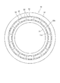
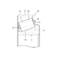
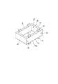
図1は、本発明の第1の実施形態に係る分割型保持器を採用した円すいころ軸受を概略的に示す側面図、図2は、図1に示される円すいころ軸受の一部の縦断面図である。
本実施形態の円すいころ軸受10は、例えば、風力発電装置の主軸を支持するために用いられる大型のものであり、環状の内輪11及び外輪12、複数の円すいころ13、並びに保持器14を備えている。
Hereinafter, embodiments of the split-type cage of the present invention will be described in detail with reference to the accompanying drawings.
FIG. 1 is a side view schematically showing a tapered roller bearing employing the split cage according to the first embodiment of the present invention, and FIG. 2 is a longitudinal section of a part of the tapered roller bearing shown in FIG. FIG.
The tapered roller bearing 10 of the present embodiment is a large-sized one used for supporting a main shaft of a wind power generator, for example, and includes an annular
内輪11の外周には、内輪軌道面11aが形成されている。外輪12の内周には、外輪軌道面12aが形成されている。複数の円すいころ13は、内輪軌道面11a及び外輪軌道面12a上を転動可能に構成されている。保持器14は、複数の円すいころ13の周方向の間隔を保持している。
本実施形態の保持器14は、複数の保持器セグメント20からなる分割型保持器とされている。なお、図1には、全ての保持器セグメント20が互いに密着した状態で示されているが、実際には、周方向の全体又は一部において、隣接する保持器セグメント20間には隙間が形成されるようになっている。
An inner
The
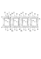
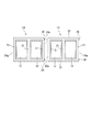
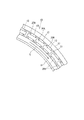
図3は保持器セグメント20の平面説明図、図4は同側面説明図、図5は同斜視図である。
保持器14を構成する各保持器セグメント20は、周方向に所定間隔をあけて対向させた一対の柱部21と、この柱部21の相互間に架設され、一対の柱部21の軸方向の端部同士を接続する一対のリム部22とを備えている。柱部21及びリム部22は、いずれも平坦な内外面を有する板形状に形成されている。したがって、保持器セグメント20は平面視で四角形の枠形状に形成されている。そして、一対の柱部21と一対のリム部22とによって囲まれた1つの空間が、1個の円すいころ13を収容するためのポケット23として構成されている。
3 is an explanatory plan view of the
Each
また、各柱部21の径方向外側及び内側の面には、径方向に突出する凸部24が形成されている。この凸部24が外輪12の内周面及び内輪11の外周面に摺接することによって、保持器セグメント20の径方向の位置決めがなされている。この保持器セグメント20は合成樹脂製であり、射出成形等によって一体成形されている。
Further,
以上の構成を有する本実施形態の円すいころ軸受10は、アキシアル荷重が付与されていない状態では、主軸からラジアル荷重を受ける負荷圏とそれ以外の反負荷圏が存在する。そして、各保持器セグメント20及び円すいころ13は、主軸の回転に伴ってラジアル荷重の負荷圏と反負荷圏との間を順次移動する。そして、例えば、円すいころ軸受10の下部域がラジアル荷重の負荷圏で上部域が反負荷圏である場合、負荷圏から反負荷圏への保持器セグメント20の移動は、負荷圏側の保持器セグメント20が反負荷圏側の保持器セグメント20を押し上げることによってなされ、反負荷圏の最上部を過ぎると保持器セグメント20は自重によって負荷圏側へ向けて落下する。
The tapered
このとき、円すいころ軸受10がグリース潤滑されていると、図10に示されるように、反負荷圏に配置された複数の保持器セグメント(符号20Aで示す)がグリースの表面張力で接着し、まとまった状態で隙間S1を埋めるように負荷圏側へ向けて矢印X方向に落下することがある。このように複数の保持器セグメント20Aがまとまって落下すると、その下側に配置された保持器セグメント(符号20Bで示す)に強く衝突し、その衝撃によって保持器セグメント20A,20Bが損傷するおそれがある。
At this time, when the tapered
特に、本実施形態では、図3に示されるように、1個の保持器セグメント20に1個の円すいころ13を収容しているので、保持器セグメント20の全数が多くなり、各保持器セグメント20の柱部21の肉厚を薄くせざるを得ない。そのため、柱部21の強度が低下し、損傷する可能性がより高くなる。
In particular, in this embodiment, as shown in FIG. 3, since one tapered
そこで、本実施形態では、複数の保持器セグメント20がグリースの表面張力で接着するのを防止するために、次のような構成を採用している。すなわち、本実施形態の保持器セグメント20は、周方向に隣接する他の保持器セグメント20に対向する対向面20aを有しており、互いに対向する対向面20aの少なくとも一方は、他方に対して、その一部において当接可能な構造を備えている。
Therefore, in the present embodiment, the following configuration is employed in order to prevent the plurality of
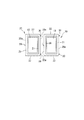
具体的に、本実施形態では、保持器セグメント20における周方向一方の対向面20aに、隣接する他の保持器セグメント20の対向面20aに向けて突出する突起部30を設けている。
この突起部30は、対向面20aの軸方向両端部、具体的には、リム部22の軸方向の厚さt(図3参照)の範囲に重複して2個設けられている。また、突起部30の先端は球面状に形成されている。そして、突起部30が、周方向に隣接する他の保持器セグメント20の対向面20aに当接することによって、対向面20a同士が全面で接触せず、対向面20a間の大部分に隙間が形成される。
Specifically, in the present embodiment, a
Two
このような構成によって、周方向に隣接する保持器セグメント20同士がグリースの表面張力によって接着してしまうのを防止することができ、上述したようにラジアル荷重の反負荷圏の最上部から保持器セグメント20を一つずつ落下させることができる。これにより、落下した保持器セグメント20が、その下側に配置された保持器セグメント20に衝突したときの衝撃を小さくし、損傷を防止することができる。
With such a configuration, it is possible to prevent the
また、突起部30は、リム部22の厚さtの範囲に重複して形成されているので、隣接する保持器セグメント20の対向面20aに当接したときの、柱部21にかかる負担を軽減することができ、柱部21の損傷を防止することができる。
また、突起部30は、先端部が球面状に形成されているので、隣接する保持器セグメント20の対向面20aに対して点接触し、その接触面積を可及的に小さくすることができる。これにより、隣接する保持器セグメント20同士がグリースの表面張力で接着してしまうのをより確実に防止することができる。
In addition, since the
Moreover, since the
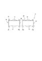
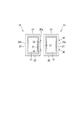
図6は、本発明の第2の実施形態に係る分割型保持器の保持器セグメント20の平面説明図である。
本実施形態の保持器セグメント20は、周方向に3個の柱部21が並べて配設され、これら柱部21と一対のリム部22との間に2個のポケット23が形成されている。そして、周方向の一方の端面(対向面20a)には、第1の実施形態と略同様の突起部30が形成されている。したがって、本実施形態においても、第1の実施形態と同様の作用効果を奏する。
FIG. 6 is an explanatory plan view of the
In the
図7は、本発明の第3の実施形態に係る分割型保持器の保持器セグメント20の平面説明図である。
本実施形態では、保持器セグメント20の周方向の両端面に突起部30が形成されている。具体的に、一方の端面には、第1の実施形態と同様に2個の突起部30が形成され、他方の端面には、柱部21の軸方向の中央部に1個の突起部30が形成されている。各突起部30は、同一の高さに形成されている。したがって、周方向に隣接する2個の保持器セグメント20は、それぞれの突起部30が相手側の対向面20aに同時に当接可能である。本実施形態においても上記第1の実施形態と同様の作用効果を奏する。
FIG. 7 is an explanatory plan view of the
In the present embodiment,
図8は、本発明の第4の実施形態に係る分割型保持器の保持器セグメント20の平面説明図である。
本実施形態では、保持器セグメント20の周方向一方の端面において、柱部21に突起部30が形成されている。また、突起部30は、柱部21の軸方向中心を基準とする対称位置に2個形成されている。本実施形態では、隣接する保持器セグメント20同士が当接したときに、柱部21にかかる負担が大きくなる点を除いては、第1の実施形態と同様の作用効果を奏する。また、2個の突起部30が軸方向に並べて形成されることで、隣接する保持器セグメント20同士が当接したときに、これらが周方向に傾いてしまうのを防止することができる。
FIG. 8 is an explanatory plan view of the
In the present embodiment, a
図9は、本発明の第5の実施形態に係る分割型保持器の保持器セグメント20の平面説明図である。
本実施形態では、突起部30の形状が他の実施形態とは異なっている。具体的には、保持器セグメント20の周方向一方の端面20aにおける軸方向中央側を円弧状に凹ませることによって、軸方向両端部を相対的に突出させ、これを突起部30としたものである。したがって、本実施形態においても、保持器セグメント20の対向面20aは、隣接する他の保持器セグメント20の対向面20aに対して一部のみにおいて当接可能となり、第1の実施形態と略同様の作用効果を奏する。ただし、本実施形態では、突起部30の先端面が平坦であるため、第1の実施形態に比べて隣接する保持器セグメント20の対向面20aへの接触面積が大きくなり、その分、グリースの表面張力で接着してしまう可能性が高くなる。
FIG. 9 is an explanatory plan view of the
In this embodiment, the shape of the
本発明は、上記実施形態に限定されるものではなく、特許請求の範囲に記載された発明の範囲内において適宜変更することが可能である。
例えば、上記実施形態では、突起部30の先端は、隣接する保持器セグメント20の対向面20aに点接触又は面接触するように構成されているが、線接触するように構成されていてもよい。また、対向面20aに形成する突起部30の数は、3個以上とすることができる。
The present invention is not limited to the above-described embodiment, and can be appropriately changed within the scope of the invention described in the claims.
For example, in the said embodiment, although the front-end | tip of the
また、1又は複数の突起部30に代えて、対向面20aの全体を凹凸形状(波形状、ジグザグ形状)に形成してもよい。この場合も、当該対向面20aは、これに対向する他の対向面20aに対してその一部が当接可能に構成される。
Further, instead of one or a plurality of
また、上記実施形態の保持器セグメント20は、1個又は2個の円すいころを収容する構成であったが、3個以上の円すいころを収容するものであってもよい。
本発明の円すいころ軸受は、風力発電装置の主軸を支持する用途に限られず、あらゆる用途に使用することができる。
Moreover, although the
The tapered roller bearing of the present invention is not limited to the use for supporting the main shaft of the wind turbine generator, and can be used for any application.
10:円すいころ軸受、11:内輪、11a:内輪軌道面、12:外輪、12a:外輪軌道面、13:円すいころ、14:分割型保持器、20:保持器セグメント、20a:対向面、21:柱部、22:リム部、23:ポケット、30:突起部 10: Tapered roller bearing, 11: Inner ring, 11a: Inner ring raceway surface, 12: Outer ring, 12a: Outer ring raceway surface, 13: Tapered roller, 14: Split cage, 20: Cage segment, 20a: Opposing surface, 21 : Pillar, 22: rim, 23: pocket, 30: protrusion
Claims (6)
前記各保持器セグメントは、周方向に隣接する他の保持器セグメントに対向する対向面を有し、
互いに対向する対向面の少なくとも一方は、他方に対してその一部において当接可能な構造を備えている、円すいころ軸受用の分割型保持器。 A split type retainer for tapered roller bearings in which a plurality of retainer segments for accommodating tapered rollers are annularly arranged along the circumferential direction,
Each of the cage segments has a facing surface facing another cage segment adjacent in the circumferential direction,
A split type cage for a tapered roller bearing, wherein at least one of opposing surfaces facing each other has a structure capable of contacting a part thereof with respect to the other.
前記突起部は、軸方向に関して前記リム部の厚さの範囲に重複して形成されている、請求項2又は3に記載の円すいころ軸受用の分割型保持器。 Each retainer segment has a plurality of pillars arranged side by side in the circumferential direction, and a rim part that connects axial ends of the pillars.
The split type retainer for a tapered roller bearing according to claim 2, wherein the protrusion is formed so as to overlap with a thickness range of the rim portion with respect to the axial direction.
Priority Applications (1)
| Application Number | Priority Date | Filing Date | Title |
|---|---|---|---|
| JP2013242022A JP2015102131A (en) | 2013-11-22 | 2013-11-22 | Split type cage for tapered roller bearing, and tapered roller bearing |
Applications Claiming Priority (1)
| Application Number | Priority Date | Filing Date | Title |
|---|---|---|---|
| JP2013242022A JP2015102131A (en) | 2013-11-22 | 2013-11-22 | Split type cage for tapered roller bearing, and tapered roller bearing |
Publications (1)
| Publication Number | Publication Date |
|---|---|
| JP2015102131A true JP2015102131A (en) | 2015-06-04 |
Family
ID=53378005
Family Applications (1)
| Application Number | Title | Priority Date | Filing Date |
|---|---|---|---|
| JP2013242022A Pending JP2015102131A (en) | 2013-11-22 | 2013-11-22 | Split type cage for tapered roller bearing, and tapered roller bearing |
Country Status (1)
| Country | Link |
|---|---|
| JP (1) | JP2015102131A (en) |
Cited By (3)
| Publication number | Priority date | Publication date | Assignee | Title |
|---|---|---|---|---|
| US20220403883A1 (en) * | 2021-06-18 | 2022-12-22 | Aktiebolaget Skf | Cage segment for a rolling-element bearing cage |
| US12287007B2 (en) | 2022-01-13 | 2025-04-29 | Aktiebolaget Skf | Cage segment for a segmented cage |
| US12467502B2 (en) | 2022-01-13 | 2025-11-11 | Aktiebolaget Skf | Bearing cage |
-
2013
- 2013-11-22 JP JP2013242022A patent/JP2015102131A/en active Pending
Cited By (4)
| Publication number | Priority date | Publication date | Assignee | Title |
|---|---|---|---|---|
| US20220403883A1 (en) * | 2021-06-18 | 2022-12-22 | Aktiebolaget Skf | Cage segment for a rolling-element bearing cage |
| US12305709B2 (en) * | 2021-06-18 | 2025-05-20 | Aktiebolaget Skf | Cage segment for a rolling-element bearing cage |
| US12287007B2 (en) | 2022-01-13 | 2025-04-29 | Aktiebolaget Skf | Cage segment for a segmented cage |
| US12467502B2 (en) | 2022-01-13 | 2025-11-11 | Aktiebolaget Skf | Bearing cage |
Similar Documents
| Publication | Publication Date | Title |
|---|---|---|
| ES2769904T3 (en) | Bearing with three rows and more of rolling bodies | |
| US8770853B2 (en) | Split cage for rolling bearing | |
| TWI499726B (en) | Large-size rolling bearing and wind power installation including the same | |
| JP2013241959A5 (en) | ||
| CA2663355A1 (en) | Tapered roller bearing with improved cage | |
| JP2014139474A (en) | Rolling bearing | |
| JP2015530549A (en) | Cage and rolling bearing | |
| CN103573806A (en) | Roller bearing for a tunneller | |
| JP2015102131A (en) | Split type cage for tapered roller bearing, and tapered roller bearing | |
| JP6089607B2 (en) | Thrust roller bearing cage | |
| JP6146013B2 (en) | Roller bearing cage and rolling bearing provided with the cage | |
| US20140086521A1 (en) | Pin-type cage and rolling bearing including the pin-type cage | |
| JP2011202714A (en) | Tapered roller bearing for wind power generator main shaft | |
| JP2014139455A (en) | Cage and thrust roller bearing having cage | |
| CN106030133A (en) | Roller bearing cage | |
| JP2012202453A (en) | Self-aligning roller bearing | |
| JP2013228064A (en) | Rolling bearing | |
| JP2018066416A (en) | Cylinder roller bearing | |
| JP2015075190A (en) | Split retainer for rolling bearing | |
| JP2014202315A (en) | Cage for roller bearing, roller bearing including the same, and wind power generator | |
| JP6142535B2 (en) | Split cage and roller bearing provided with split cage | |
| JP2014020391A (en) | Roller bearing | |
| JP2015021550A (en) | Rolling bearing | |
| JP2015175457A (en) | Bearing, and method of manufacturing bearing | |
| RU2006138364A (en) | ROLLING BEARING RADIAL ROLLER SEPARATE |