JP2015102156A - Split cage and roller bearing - Google Patents
Split cage and roller bearing Download PDFInfo
- Publication number
- JP2015102156A JP2015102156A JP2013242857A JP2013242857A JP2015102156A JP 2015102156 A JP2015102156 A JP 2015102156A JP 2013242857 A JP2013242857 A JP 2013242857A JP 2013242857 A JP2013242857 A JP 2013242857A JP 2015102156 A JP2015102156 A JP 2015102156A
- Authority
- JP
- Japan
- Prior art keywords
- cage
- cage segment
- roller
- peripheral surface
- Prior art date
- Legal status (The legal status is an assumption and is not a legal conclusion. Google has not performed a legal analysis and makes no representation as to the accuracy of the status listed.)
- Granted
Links
Images


Classifications
-
- F—MECHANICAL ENGINEERING; LIGHTING; HEATING; WEAPONS; BLASTING
- F16—ENGINEERING ELEMENTS AND UNITS; GENERAL MEASURES FOR PRODUCING AND MAINTAINING EFFECTIVE FUNCTIONING OF MACHINES OR INSTALLATIONS; THERMAL INSULATION IN GENERAL
- F16C—SHAFTS; FLEXIBLE SHAFTS; ELEMENTS OR CRANKSHAFT MECHANISMS; ROTARY BODIES OTHER THAN GEARING ELEMENTS; BEARINGS
- F16C33/00—Parts of bearings; Special methods for making bearings or parts thereof
- F16C33/30—Parts of ball or roller bearings
- F16C33/46—Cages for rollers or needles
- F16C33/467—Details of individual pockets, e.g. shape or roller retaining means
-
- F—MECHANICAL ENGINEERING; LIGHTING; HEATING; WEAPONS; BLASTING
- F16—ENGINEERING ELEMENTS AND UNITS; GENERAL MEASURES FOR PRODUCING AND MAINTAINING EFFECTIVE FUNCTIONING OF MACHINES OR INSTALLATIONS; THERMAL INSULATION IN GENERAL
- F16C—SHAFTS; FLEXIBLE SHAFTS; ELEMENTS OR CRANKSHAFT MECHANISMS; ROTARY BODIES OTHER THAN GEARING ELEMENTS; BEARINGS
- F16C17/00—Sliding-contact bearings for exclusively rotary movement
- F16C17/12—Sliding-contact bearings for exclusively rotary movement characterised by features not related to the direction of the load
- F16C17/22—Sliding-contact bearings for exclusively rotary movement characterised by features not related to the direction of the load with arrangements compensating for thermal expansion
-
- F—MECHANICAL ENGINEERING; LIGHTING; HEATING; WEAPONS; BLASTING
- F16—ENGINEERING ELEMENTS AND UNITS; GENERAL MEASURES FOR PRODUCING AND MAINTAINING EFFECTIVE FUNCTIONING OF MACHINES OR INSTALLATIONS; THERMAL INSULATION IN GENERAL
- F16C—SHAFTS; FLEXIBLE SHAFTS; ELEMENTS OR CRANKSHAFT MECHANISMS; ROTARY BODIES OTHER THAN GEARING ELEMENTS; BEARINGS
- F16C19/00—Bearings with rolling contact, for exclusively rotary movement
- F16C19/22—Bearings with rolling contact, for exclusively rotary movement with bearing rollers essentially of the same size in one or more circular rows, e.g. needle bearings
- F16C19/34—Bearings with rolling contact, for exclusively rotary movement with bearing rollers essentially of the same size in one or more circular rows, e.g. needle bearings for both radial and axial load
- F16C19/36—Bearings with rolling contact, for exclusively rotary movement with bearing rollers essentially of the same size in one or more circular rows, e.g. needle bearings for both radial and axial load with a single row of rollers
- F16C19/364—Bearings with rolling contact, for exclusively rotary movement with bearing rollers essentially of the same size in one or more circular rows, e.g. needle bearings for both radial and axial load with a single row of rollers with tapered rollers, i.e. rollers having essentially the shape of a truncated cone
-
- F—MECHANICAL ENGINEERING; LIGHTING; HEATING; WEAPONS; BLASTING
- F16—ENGINEERING ELEMENTS AND UNITS; GENERAL MEASURES FOR PRODUCING AND MAINTAINING EFFECTIVE FUNCTIONING OF MACHINES OR INSTALLATIONS; THERMAL INSULATION IN GENERAL
- F16C—SHAFTS; FLEXIBLE SHAFTS; ELEMENTS OR CRANKSHAFT MECHANISMS; ROTARY BODIES OTHER THAN GEARING ELEMENTS; BEARINGS
- F16C33/00—Parts of bearings; Special methods for making bearings or parts thereof
- F16C33/30—Parts of ball or roller bearings
- F16C33/46—Cages for rollers or needles
- F16C33/4605—Details of interaction of cage and race, e.g. retention or centring
-
- F—MECHANICAL ENGINEERING; LIGHTING; HEATING; WEAPONS; BLASTING
- F16—ENGINEERING ELEMENTS AND UNITS; GENERAL MEASURES FOR PRODUCING AND MAINTAINING EFFECTIVE FUNCTIONING OF MACHINES OR INSTALLATIONS; THERMAL INSULATION IN GENERAL
- F16C—SHAFTS; FLEXIBLE SHAFTS; ELEMENTS OR CRANKSHAFT MECHANISMS; ROTARY BODIES OTHER THAN GEARING ELEMENTS; BEARINGS
- F16C33/00—Parts of bearings; Special methods for making bearings or parts thereof
- F16C33/30—Parts of ball or roller bearings
- F16C33/46—Cages for rollers or needles
- F16C33/467—Details of individual pockets, e.g. shape or roller retaining means
- F16C33/4676—Details of individual pockets, e.g. shape or roller retaining means of the stays separating adjacent cage pockets, e.g. guide means for the bearing-surface of the rollers
-
- F—MECHANICAL ENGINEERING; LIGHTING; HEATING; WEAPONS; BLASTING
- F16—ENGINEERING ELEMENTS AND UNITS; GENERAL MEASURES FOR PRODUCING AND MAINTAINING EFFECTIVE FUNCTIONING OF MACHINES OR INSTALLATIONS; THERMAL INSULATION IN GENERAL
- F16C—SHAFTS; FLEXIBLE SHAFTS; ELEMENTS OR CRANKSHAFT MECHANISMS; ROTARY BODIES OTHER THAN GEARING ELEMENTS; BEARINGS
- F16C33/00—Parts of bearings; Special methods for making bearings or parts thereof
- F16C33/30—Parts of ball or roller bearings
- F16C33/46—Cages for rollers or needles
- F16C33/51—Cages for rollers or needles formed of unconnected members
- F16C33/513—Cages for rollers or needles formed of unconnected members formed of arcuate segments for carrying one or more rollers
-
- F—MECHANICAL ENGINEERING; LIGHTING; HEATING; WEAPONS; BLASTING
- F16—ENGINEERING ELEMENTS AND UNITS; GENERAL MEASURES FOR PRODUCING AND MAINTAINING EFFECTIVE FUNCTIONING OF MACHINES OR INSTALLATIONS; THERMAL INSULATION IN GENERAL
- F16C—SHAFTS; FLEXIBLE SHAFTS; ELEMENTS OR CRANKSHAFT MECHANISMS; ROTARY BODIES OTHER THAN GEARING ELEMENTS; BEARINGS
- F16C33/00—Parts of bearings; Special methods for making bearings or parts thereof
- F16C33/30—Parts of ball or roller bearings
- F16C33/46—Cages for rollers or needles
- F16C33/56—Selection of substances
-
- F—MECHANICAL ENGINEERING; LIGHTING; HEATING; WEAPONS; BLASTING
- F16—ENGINEERING ELEMENTS AND UNITS; GENERAL MEASURES FOR PRODUCING AND MAINTAINING EFFECTIVE FUNCTIONING OF MACHINES OR INSTALLATIONS; THERMAL INSULATION IN GENERAL
- F16C—SHAFTS; FLEXIBLE SHAFTS; ELEMENTS OR CRANKSHAFT MECHANISMS; ROTARY BODIES OTHER THAN GEARING ELEMENTS; BEARINGS
- F16C33/00—Parts of bearings; Special methods for making bearings or parts thereof
- F16C33/30—Parts of ball or roller bearings
- F16C33/58—Raceways; Race rings
- F16C33/583—Details of specific parts of races
- F16C33/585—Details of specific parts of races of raceways, e.g. ribs to guide the rollers
-
- F—MECHANICAL ENGINEERING; LIGHTING; HEATING; WEAPONS; BLASTING
- F16—ENGINEERING ELEMENTS AND UNITS; GENERAL MEASURES FOR PRODUCING AND MAINTAINING EFFECTIVE FUNCTIONING OF MACHINES OR INSTALLATIONS; THERMAL INSULATION IN GENERAL
- F16C—SHAFTS; FLEXIBLE SHAFTS; ELEMENTS OR CRANKSHAFT MECHANISMS; ROTARY BODIES OTHER THAN GEARING ELEMENTS; BEARINGS
- F16C2202/00—Solid materials defined by their properties
- F16C2202/20—Thermal properties
- F16C2202/22—Coefficient of expansion
Landscapes
- Engineering & Computer Science (AREA)
- General Engineering & Computer Science (AREA)
- Mechanical Engineering (AREA)
- Rolling Contact Bearings (AREA)
Abstract
Description
本発明は、分割保持器及びころ軸受に関する。 The present invention relates to a split cage and a roller bearing.
従来、ころ軸受の内外輪間を転動する複数のころを周方向に沿って所定間隔毎に保持する保持器として、単一のころを収容する単一のポケットを有する保持器セグメントを周方向に沿って環状に配列した分割保持器が知られている(例えば特許文献1参照)。このような分割保持器としては、内輪及び外輪との接触による摩耗を防止するために、ころによって回転案内されるころ案内タイプのものが多用されている。 Conventionally, as a cage that holds a plurality of rollers rolling between inner and outer rings of a roller bearing at predetermined intervals along the circumferential direction, a cage segment having a single pocket that accommodates a single roller is circumferential. There are known split cages arranged in a ring shape along the line (for example, see Patent Document 1). As such a split cage, in order to prevent wear due to contact with the inner ring and the outer ring, a roller guide type that is rotationally guided by rollers is frequently used.
上記ころ案内タイプの分割保持器にあっては、各保持器セグメントはころによって回転案内されるため、通常時は、保持器セグメントと外輪内周面との間には、所定の径方向隙間が形成されている。このため、保持器セグメントが熱膨張すると、隣接する保持器セグメント間の円周方向隙間が詰まることにより、保持器セグメントは周方向への逃げ場を失って径方向外方(外輪内周面側)に移動する場合がある。この場合、各保持器セグメントにおいてころと摺接するポケット面の径方向内側部は、熱膨張によりころに強く押し付けられた状態で径方向外方に移動するため、ころとの間で異常摩耗が発生するという問題があった。
本発明は、前記問題点に鑑みてなされたものであり、隣接する保持器セグメント間に隙間詰まりが発生しても、保持器セグメントのポケット面に異常摩耗が発生するのを防止することができる分割保持器及びころ軸受を提供することを目的とする。
In the above roller guide type split cage, each cage segment is rotationally guided by rollers, so that a normal radial clearance is normally provided between the cage segment and the outer peripheral surface of the outer ring. Is formed. For this reason, when the cage segment is thermally expanded, the circumferential gap between the adjacent cage segments is clogged, and the cage segment loses a clearance in the circumferential direction and is radially outward (outer ring inner circumferential surface side). May move to. In this case, the radially inner portion of the pocket surface in sliding contact with the rollers in each cage segment moves outward in the radial direction while being strongly pressed against the rollers by thermal expansion, so abnormal wear occurs between the rollers. There was a problem to do.
The present invention has been made in view of the above problems, and can prevent abnormal wear from occurring on the pocket surface of the cage segment even if a gap clogging occurs between adjacent cage segments. An object is to provide a split cage and a roller bearing.
(1)本発明の分割保持器は、軸方向に所定間隔を隔てて互いに対向する一対のリム部と、前記一対のリム部の間に架設され当該一対のリム部とともにころを収容するためのポケットを区画形成する複数の柱部とを有し、前記柱部の前記ポケット側の側面を前記ころの外周面と摺接可能なポケット面とした保持器セグメントを複数備え、前記複数の保持器セグメントは、内輪と外輪との間の環状空間において周方向に沿って環状に配列された状態で前記ころにより回転案内されるころ軸受用の分割保持器であって、前記柱部のポケット面の径方向内側部と前記ころの外周面との間における径方向隙間は、前記保持器セグメントが熱膨張により径方向外方に移動したときの当該保持器セグメントのピッチ円半径の変化量よりも大きく設定されていることを特徴とする。 (1) A split cage according to the present invention is configured to accommodate a roller together with a pair of rim portions opposed to each other at a predetermined interval in an axial direction and the pair of rim portions. A plurality of retainer segments, each having a plurality of pillar portions defining a pocket, wherein the pocket-side side surface of the pillar portion is a pocket surface slidably contactable with an outer peripheral surface of the roller. The segment is a split cage for a roller bearing that is rotationally guided by the rollers in an annular space between the inner ring and the outer ring in an annular arrangement along the circumferential direction. The radial clearance between the radially inner portion and the outer peripheral surface of the roller is larger than the amount of change in the pitch circle radius of the cage segment when the cage segment moves radially outward due to thermal expansion. Set And wherein the Rukoto.
上記のように構成された分割保持器によれば、保持器セグメントが熱膨張により径方向外方に移動しても、ポケット面の径方向内側部ところの外周面との間に隙間が残るため、ポケット面の径方向内側部がころの外周面に押圧されるのを回避することができる。これにより、保持器セグメントの熱膨張により隣接する保持器セグメント間に隙間詰まりが発生しても、保持器セグメントのポケット面に異常摩耗が発生するのを防止することができる。 According to the split cage configured as described above, even when the cage segment moves radially outward due to thermal expansion, a gap remains between the pocket surface and the outer peripheral surface at the radially inner portion. It is possible to avoid the radially inner portion of the pocket surface being pressed against the outer peripheral surface of the roller. Thereby, even if gap clogging occurs between adjacent cage segments due to thermal expansion of the cage segment, it is possible to prevent abnormal wear from occurring on the pocket surface of the cage segment.
(2)前記ポケット面は、径方向内側において径方向内端を除く部分が前記ころの外周面と接触するように傾斜して形成された内側傾斜面と、径方向外側において径方向外端を除く部分が前記ころの外周面と接触するように傾斜して形成された外側傾斜面とを有していることが好ましい。
この場合、ころの外周面は、通常時にはポケット面の内側傾斜面及び外側傾斜面にそれぞれ接触することで、ポケット面の径方向外端及び径方向内端に接触することがないので、これらの接触に起因して保持器セグメントが破損するのを防止することができる。
(2) The pocket surface includes an inner inclined surface formed so as to be inclined such that a portion excluding the radially inner end on the radially inner side contacts the outer peripheral surface of the roller, and a radially outer end on the radially outer side. It is preferable that the part except for has an outer inclined surface formed so as to be inclined so as to come into contact with the outer peripheral surface of the roller.
In this case, the outer peripheral surface of the roller normally contacts the inner inclined surface and the outer inclined surface of the pocket surface, so that it does not contact the radially outer end and the radially inner end of the pocket surface. It is possible to prevent the cage segment from being damaged due to the contact.
(3)本発明のころ軸受は、内輪と、外輪と、前記内外輪の間の環状空間に転動可能に配置された複数のころと、上記(1)又は(2)の分割保持器とを備えていることを特徴する。
上記のように構成されたころ軸受によれば、上述した分割保持器と同様の作用効果を奏する。
(3) A roller bearing according to the present invention includes an inner ring, an outer ring, a plurality of rollers arranged to roll in an annular space between the inner and outer rings, and the split cage according to (1) or (2) above. It is characterized by having.
According to the roller bearing comprised as mentioned above, there exists an effect similar to the division | segmentation holder | retainer mentioned above.
本発明の分割保持器によれば、隣接する保持器セグメント間に隙間詰まりが発生しても、保持器セグメントのポケット面に異常摩耗が発生するのを防止することができる。 According to the split cage of the present invention, even if a gap clogging occurs between adjacent cage segments, it is possible to prevent abnormal wear from occurring on the pocket surface of the cage segment.
以下、本発明の実施形態について添付図面を参照しながら詳述する。
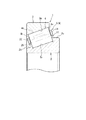
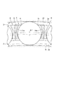
図1は、本発明の第1実施形態に係る分割保持器を備えた円すいころ軸受を示す要部断面図である。本実施形態の円すいころ軸受1は、内輪2と、外輪3と、内輪2と外輪3との間の環状空間に転動可能に配置された複数の円すいころ4と、各円すいころ4を保持する分割保持器5とを備えている。
Hereinafter, embodiments of the present invention will be described in detail with reference to the accompanying drawings.
FIG. 1 is a cross-sectional view of an essential part showing a tapered roller bearing provided with a split cage according to a first embodiment of the present invention. The tapered roller bearing 1 according to the present embodiment holds an
外輪3の内周には、円すいころ4が転動するように、円すい面からなる外輪軌道面3aが形成されている。内輪2の外周には、外輪軌道面3aと対向する位置に円すいころ4が転動するように、円すい面からなる内輪軌道面2aが形成されている。外輪軌道面3a及び内輪軌道面2aには、全周に亘ってグリース等の潤滑剤が塗布されている。内輪2の外周には、内輪軌道面2aを挟んで径方向外方に突出し、円すいころ4の軸方向一方側の第1端面4aが接触する大鍔部2bと、円すいころ4の軸方向他方側の第2端面4bが接触可能な小鍔部2cとが形成されている。
An outer
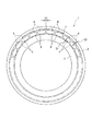
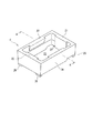
図2は、円すいころ軸受1を示す側面図である。また、図3は、分割保持器5を構成する保持器セグメント6を示す斜視図である。分割保持器5は、複数の保持器セグメント6を、内輪2と外輪3との間の環状空間において周方向に沿って環状に配列することによって構成されている。各保持器セグメント6は、円すいころ4によって回転案内される。このため、各保持器セグメント6の内周面と内輪2の外周面との間、及び各保持器セグメント6の外周面と外輪3の内周面との間には、それぞれ所定の径方向隙間S1,S2が形成されている。また、隣接する保持器セグメント6間には、所定の円周方向隙間S3が形成されている。
FIG. 2 is a side view showing the tapered roller bearing 1. FIG. 3 is a perspective view showing a
保持器セグメント6は、射出成形によって矩形枠状に一体成形された合成樹脂製のものである。保持器セグメント6は、軸方向に所定間隔を隔てて互いに対向する第1リム部21及び第2リム部22と、各リム部21,22の相互間に架設された第1柱部23及び第2柱部24とを備えている。保持器セグメント6には、各リム部21,22と各柱部23,24とによって、単一の円すいころ4を収容するための単一のポケット25が区画形成されている。
The
図4は、図3のA−A矢視断面図である。図3及び図4に示すように、ポケット25の径方向外側には、径方向外方から円すいころ4を挿入可能な挿入口25aが形成されている。各柱部23,24のポケット面23a,24a(後述)の径方向外端部には、円すいころ4を挿入口25aから挿入し易いようにR面取り23a3,24a3が施されている。
4 is a cross-sectional view taken along line AA in FIG. As shown in FIGS. 3 and 4, an
各柱部23,24のポケットP側の側面は、円すいころ4の外周面4cと摺接可能なポケット面23a,24aとされている。各ポケット面23a,24aの径方向内側には内側傾斜面23a1,24a1がそれぞれ形成され、各ポケット面23a,24aの径方向外側には外側傾斜面23a2,24a2がそれぞれ形成されている。
Side surfaces on the pocket P side of the
内側傾斜面23a1,24a1は、ポケット面23a,24aの径方向内端b1,b2を除く部分の一部が円すいころ4の外周面4cと線接触するように傾斜して形成されている。外側傾斜面23a2,24a2は、ポケット面23a,24aの径方向外端c1,c2を除く部分の一部が円すいころ4の外周面4cと線接触するように傾斜して形成されている。
The inner inclined surfaces 23a1 and 24a1 are formed so as to be inclined so that part of the portions of the pocket surfaces 23a and 24a excluding the radially inner ends b1 and b2 are in line contact with the outer
したがって、円すいころ4は、通常時には、その外周面4cが内側傾斜面23a1,24a1及び外側傾斜面23a2,24a2にそれぞれ接触することで、ポケット面23a,24aの径方向内端b1,b2及び径方向外端c1,c2に接触するのを防止することができる。これにより、円すいころ4とポケット面23a,24aの径方向内端b1,b2及び径方向外端c1,c2との接触に起因して保持器セグメント6が破損するのを防止することができる。
Accordingly, in the normal state, the outer
図4に示すように、各ポケット面23a,24aの径方向内側部である内側傾斜面23a1,24a1と、円すいころ4の外周面4cとの間には、径方向隙間S4,S5が形成されている。この径方向隙間S4,S5は、保持器セグメント6が熱膨張により径方向外方(図中上側)に移動したときの保持器セグメント6のピッチ円半径の変化量Δdよりも大きく設定されている。
As shown in FIG. 4, radial clearances S4 and S5 are formed between the inner inclined surfaces 23a1 and 24a1 that are radially inner portions of the pocket surfaces 23a and 24a and the outer
これにより、図5に示すように、保持器セグメント6が熱膨張により前記変化量Δdだけ径方向外方に移動しても、ポケット面23a,24aの内側傾斜面23a1,24a1と円すいころ4の外周面4cとの間に径方向隙間が残るため、前記内側傾斜面23a1,24a1が円すいころ4の外周面4cに押圧されるのを回避することができる。したがって、保持器セグメント6の熱膨張により隣接する保持器セグメント6間の円周方向隙間S3(図2参照)が無くなる隙間詰まりが発生して、保持器セグメント6が径方向外方に移動しても、保持器セグメント6のポケット面23a,24aに異常摩耗が発生するのを防止することができる。
As a result, as shown in FIG. 5, even if the
図3において、保持器セグメント6の第1リム部21の内周面の長手方向(周方向)両端部には、径方向内方に突出する第1突出部26及び第2突出部27が一体に形成されている。また、第2リム部22の内周面の長手方向(周方向)両端部には、径方向内方に突出する第3突出部28及び第4突出部29が一体に形成されている。
In FIG. 3, a first projecting
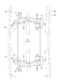
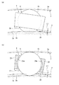
図6は、保持器セグメント6が一方向に自転し始めたときの状態を示しており、図6(a)は側面図、図6(b)は断面図である。図6(b)に示すように、第1突出部26の突出長さL1は、保持器セグメント6が円すいころ4の軸線を中心として一方向(図中の時計回り方向)に自転し始めると、当該第1突出部26が内輪2の大鍔部2bの外周面に当接する長さ寸法に設定されている。また、図6(a)に示すように、第3突出部28の突出長さL3は、保持器セグメント6が一方向に自転し始めると、当該第3突出部28が内輪2の小鍔部2cの外周面に当接する長さ寸法に設定されている。
6A and 6B show a state when the
したがって、保持器セグメント6が一方向に自転し始めると、第1突出部26及び第3突出部28が内輪2の大鍔部2b及び小鍔部2cの各外周面にそれぞれ当接するため、保持器セグメント6が一方向にそれ以上自転するのを防止することができる。これにより、保持器セグメント6がその自転により円すいころ4に巻き込まれて破損するのを防止することができる。
Therefore, when the
図7は、保持器セグメント6が他方向に自転し始めたときの状態を示しており、図7(a)は側面図、図7(b)は断面図である。図7(b)に示すように、第2突出部27の突出長さL2は、保持器セグメント6が円すいころ4の軸線を中心として他方向(図中の反時計回り方向)に自転し始めると、当該第2突出部27が内輪2の大鍔部2bの外周面に当接する長さ寸法に設定されている。また、図7(a)に示すように、第4突出部29の突出長さL4は、保持器セグメント6が他方向に自転し始めると、当該第4突出部29が内輪2の小鍔部2cの外周面に当接する長さ寸法に設定されている。
FIG. 7 shows a state when the
したがって、保持器セグメント6が他方向に自転し始めると、第2突出部27及び第4突出部29が内輪2の大鍔部2b及び小鍔部2cの各外周面にそれぞれ当接するため、保持器セグメント6が他方向にそれ以上自転するのを防止することができる。これにより、保持器セグメント6がその自転により円すいころ4に巻き込まれて破損するのを防止することができる。
Accordingly, when the
図8は、保持器セグメント6が径方向内方へずれたときの状態を示しており、図8(a)は側面図、図8(b)は断面図である。図8(b)に示すように、第1及び第2突出部26,27の各突出長さL1,L2は、保持器セグメント6が径方向内方へずれたときに、つまりポケット25の挿入口25aが、当該挿入口25aから円すいころ4が抜け出す方向に移動したときに、保持器セグメント6が円すいころ4から外れる前に、当該第1及び第2突出部26,27が内輪2の大鍔部2bの外周面に当接する長さ寸法に設定されている。また、図8(a)に示すように、第3及び第4突出部28,29の各突出長さL3,L4は、保持器セグメント6が径方向内方へずれたときに、保持器セグメント6が円すいころ4から外れる前に、当該第3突出部28及び第4突出部29が内輪2の小鍔部2cの外周面に当接する長さ寸法に設定されている。
FIG. 8 shows a state where the
したがって、保持器セグメント6が振動等により径方向内方にずれたときに、保持器セグメント6が円すいころ4から外れる前に、第1〜第4突出部26〜29が内輪2の大鍔部2b及び小鍔部2cの各外周面に当接する。これにより、保持器セグメント6が円すいころ4から外れて破損するのを防止することができる。
Therefore, when the
また、保持器セグメント6が自転し始めたとき、又は保持器セグメント6が振動等により径方向内方にずれたとき、第1〜第4突出部26〜29は、内輪2の大鍔部2b及び小鍔部2cの各外周面に当接するため、内輪軌道面2a上の潤滑剤が第1〜第4突出部26〜29により剥ぎ取られるのを防止することができる。
Further, when the
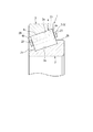
図9は、本発明の第2実施形態に係る分割保持器5を備えた円すいころ軸受1を示す要部断面図である。また、図10は、分割保持器5を構成する保持器セグメント6を示す斜視図である。
本実施形態における保持器セグメント6では、第1〜第4突出部26〜29が第1及び第2柱部23,24の内周面に突設されている。具体的には、第1柱部23の内周面の長手方向(軸方向)両端部に、径方向内方に突出する第2突出部27及び第4突出部29が一体に形成されている。第2柱部24の内周面の長手方向(軸方向)両端部に、径方向内方に突出する第1突出部26及び第3突出部28が一体に形成されている。
FIG. 9 is a cross-sectional view of an essential part showing a tapered
In the
図11(a)は、本実施形態の保持器セグメント6が一方向に自転し始めたときの状態を示す側面図である。図11(a)に示すように、第1及び第3突出部26,28の突出長さL1,L3は、保持器セグメント6が円すいころ4の軸線を中心として一方向(図中の時計回り方向)に自転し始めると、当該第1及び第3突出部26,28が内輪軌道面2aに当接する長さ寸法に設定されている。
したがって、保持器セグメント6が一方向に自転し始めると、第1突出部26及び第3突出部28が内輪軌道面2aに当接するため、保持器セグメント6が一方向にそれ以上自転するのを防止することができる。
FIG. 11A is a side view showing a state when the
Therefore, when the
図11(b)は、本実施形態の保持器セグメント6が他方向に自転し始めたときの状態を示す側面図である。図11(b)に示すように、第2及び第4突出部27,29の突出長さL2,L4は、保持器セグメント6が円すいころ4の軸線を中心として他方向(図中の反時計回り方向)に自転し始めると、当該第2及び第4突出部27,29が内輪軌道面2aに当接する長さ寸法に設定されている。
したがって、保持器セグメント6が他方向に自転し始めると、第2突出部27及び第4突出部29が内輪軌道面2aに当接するため、保持器セグメント6が他方向にそれ以上自転するのを防止することができる。
FIG. 11B is a side view showing a state when the
Therefore, when the
図12は、保持器セグメント6が径方向内方へずれたときの状態を示す側面図である。図12に示すように、第1〜第4突出部26〜29の各突出長さL1〜L4は、保持器セグメント6が径方向内方へずれたときに、保持器セグメント6が円すいころ4から外れる前に、当該第1〜第4突出部26〜29が内輪軌道面2aに当接する長さ寸法に設定されている。
FIG. 12 is a side view showing a state when the
したがって、保持器セグメント6が振動等により径方向内方にずれたときに、保持器セグメント6が円すいころ4から外れる前に、第1〜第4突出部26〜29が内輪軌道面2aに当接する。これにより、保持器セグメント6が円すいころ4から外れて破損するのを防止することができる。
なお、第2実施形態において説明を省略した点は、第1実施形態と同様である。
Accordingly, when the
In addition, the point which abbreviate | omitted description in 2nd Embodiment is the same as that of 1st Embodiment.
図13は、本発明の第3実施形態に係る分割保持器5を備えた円すいころ軸受1を示す要部断面図である。また、図14は、分割保持器5を構成する保持器セグメント6を示す斜視図である。
本実施形態における保持器セグメント6では、第1〜第4突出部26〜29が第1及び第2柱部23,24の外周面に突設されている。具体的には、第1柱部23の外周面の長手方向(軸方向)両端部に、径方向外方に突出する第2突出部27及び第4突出部29が一体に形成されている。第2柱部24の外周面の長手方向(軸方向)両端部に、径方向外方に突出する第1突出部26及び第3突出部28が一体に形成されている。
FIG. 13: is principal part sectional drawing which shows the tapered
In the
図15は、図14のB−B矢視断面図である。図14及び図15に示すように、ポケット25の径方向内側には、径方向内方から円すいころ4を挿入可能な挿入口25aが形成されている。各柱部23,24のポケット面23a,24aの径方向内端部には、円すいころ4を挿入口25aから挿入し易いようにR面取り23a3,24a3が施されている。
15 is a cross-sectional view taken along line BB in FIG. As shown in FIGS. 14 and 15, an
図16(a)は、本実施形態の保持器セグメント6が一方向に自転し始めたときの状態を示す側面図である。図16(a)に示すように、第2及び第4突出部27,29の突出長さL2,L4は、保持器セグメント6が円すいころ4の軸線を中心として一方向(図中の時計回り方向)に自転し始めると、当該第2及び第4突出部27,29が外輪軌道面3aに当接する長さ寸法に設定されている。
したがって、保持器セグメント6が一方向に自転し始めると、第2突出部27及び第4突出部29が外輪軌道面3aに当接するため、保持器セグメント6が一方向にそれ以上自転するのを防止することができる。
FIG. 16A is a side view showing a state when the
Accordingly, when the
図16(b)は、本実施形態の保持器セグメント6が他方向に自転し始めたときの状態を示す側面図である。図16(b)に示すように、第1及び第3突出部26,28の突出長さL1,L3は、保持器セグメント6が円すいころ4の軸線を中心として他方向(図中の反時計回り方向)に自転し始めると、当該第1及び第3突出部26,28が外輪軌道面3aに当接する長さ寸法に設定されている。
したがって、保持器セグメント6が他方向に自転し始めると、第1突出部26及び第3突出部28が外輪軌道面3aに当接するため、保持器セグメント6が他方向にそれ以上自転するのを防止することができる。
FIG. 16B is a side view showing a state when the
Therefore, when the
図17は、保持器セグメント6が径方向外方へずれたときの状態を示す側面図である。図17に示すように、第1〜第4突出部26〜29の各突出長さL1〜L4は、保持器セグメント6が径方向外方へずれたときに、つまりポケット25の挿入口25aが、当該挿入口25aから円すいころ4が抜け出す方向に移動したときに、持器セグメント6が円すいころ4から外れる前に、当該第1〜第4突出部26〜29が外輪軌道面3aに当接する長さ寸法に設定されている。
FIG. 17 is a side view showing a state when the
したがって、保持器セグメント6が振動等により径方向外方にずれたときに、保持器セグメント6が円すいころ4から外れる前に、第1〜第4突出部26〜29が外輪軌道面3aに当接する。これにより、保持器セグメント6が円すいころ4から外れて破損するのを防止することができる。
なお、第3実施形態において説明を省略した点は、第1実施形態と同様である。
Therefore, when the
In addition, the point which abbreviate | omitted description in 3rd Embodiment is the same as that of 1st Embodiment.
本発明は、上記の実施形態に限定されることなく適宜変更して実施可能である。例えば、上記各実施形態では、保持器セグメント6に突出部26〜29を設けた例を示しているが、これら突出部26〜29は必ずしも設けられていなくても良い。また、上記各実施形態における保持器セグメント6には、単一の円すいころ4を収容する単一のポケット25が区画形成されているが、複数の円すいころ4を個別に収容する複数のポケット25が区画形成されていても良い。また、上記各実施形態における保持器セグメント6は、合成樹脂製のもの以外に、アルミニウム製等の線膨張係数が大きい金属製のものにも好適に適用することができる。また、本発明は、円すいころ軸受以外に、円筒ころ軸受にも適用することができる。
The present invention is not limited to the above embodiment and can be implemented with appropriate modifications. For example, although each said embodiment showed the example which provided the protrusion parts 26-29 in the holder |
1:円すいころ軸受(ころ軸受)、2:内輪、3:外輪、4:円すいころ(ころ)ころ、5:分割保持器、6:保持器セグメント、21:第1リム部、22:第2リム部、23:第1柱部、23a:ポケット面、23a1:内側傾斜面、23a2:外側傾斜面、24:第2柱部、24a:ポケット面、24a1:内側傾斜面、24a2:外側傾斜面、25:ポケット、26:第1突出部、27:第2突出部、28:第3突出部、29:第4突出部、S4:径方向隙間、S5:径方向隙間、Δd:変化量 1: Tapered roller bearing (roller bearing), 2: inner ring, 3: outer ring, 4: tapered roller (roller) roller, 5: split cage, 6: cage segment, 21: first rim portion, 22: second Rim part, 23: 1st pillar part, 23a: Pocket surface, 23a1: Inner inclined surface, 23a2: Outer inclined surface, 24: Second pillar part, 24a: Pocket surface, 24a1: Inner inclined surface, 24a2: Outer inclined surface , 25: pocket, 26: first protrusion, 27: second protrusion, 28: third protrusion, 29: fourth protrusion, S4: radial gap, S5: radial gap, Δd: change amount
Claims (3)
前記複数の保持器セグメントは、内輪と外輪との間の環状空間において周方向に沿って環状に配列された状態で前記ころにより回転案内されるころ軸受用の分割保持器であって、
前記柱部のポケット面の径方向内側部と前記ころの外周面との間における径方向隙間は、前記保持器セグメントが熱膨張により径方向外方に移動したときの当該保持器セグメントのピッチ円半径の変化量よりも大きく設定されていることを特徴とする分割保持器。 A pair of rim portions opposed to each other at a predetermined interval in the axial direction, and a plurality of pillar portions that are spanned between the pair of rim portions and define a pocket for accommodating a roller together with the pair of rim portions. A plurality of retainer segments having a pocket side surface that can be slidably contacted with an outer peripheral surface of the roller, the side surface of the column portion on the pocket side;
The plurality of cage segments are divided cages for roller bearings that are rotationally guided by the rollers in a state of being annularly arranged along a circumferential direction in an annular space between an inner ring and an outer ring,
The radial gap between the radially inner portion of the pocket surface of the pillar portion and the outer peripheral surface of the roller is the pitch circle of the cage segment when the cage segment moves radially outward due to thermal expansion. A split cage characterized by being set larger than the amount of change in radius.
Priority Applications (4)
| Application Number | Priority Date | Filing Date | Title |
|---|---|---|---|
| JP2013242857A JP6295621B2 (en) | 2013-11-25 | 2013-11-25 | Split cage and roller bearing |
| US14/543,250 US9316255B2 (en) | 2013-11-25 | 2014-11-17 | Split cage and roller bearing |
| EP14194075.9A EP2876320B1 (en) | 2013-11-25 | 2014-11-20 | Split Cage And Roller Bearing |
| CN201410690714.XA CN104653626B (en) | 2013-11-25 | 2014-11-25 | Split retainer and roller bearing |
Applications Claiming Priority (1)
| Application Number | Priority Date | Filing Date | Title |
|---|---|---|---|
| JP2013242857A JP6295621B2 (en) | 2013-11-25 | 2013-11-25 | Split cage and roller bearing |
Publications (2)
| Publication Number | Publication Date |
|---|---|
| JP2015102156A true JP2015102156A (en) | 2015-06-04 |
| JP6295621B2 JP6295621B2 (en) | 2018-03-20 |
Family
ID=51932256
Family Applications (1)
| Application Number | Title | Priority Date | Filing Date |
|---|---|---|---|
| JP2013242857A Expired - Fee Related JP6295621B2 (en) | 2013-11-25 | 2013-11-25 | Split cage and roller bearing |
Country Status (4)
| Country | Link |
|---|---|
| US (1) | US9316255B2 (en) |
| EP (1) | EP2876320B1 (en) |
| JP (1) | JP6295621B2 (en) |
| CN (1) | CN104653626B (en) |
Families Citing this family (6)
| Publication number | Priority date | Publication date | Assignee | Title |
|---|---|---|---|---|
| US10054163B2 (en) | 2016-11-15 | 2018-08-21 | General Electric Company | Bearing cages for roller bearing assemblies |
| CN109844338B (en) | 2016-12-01 | 2022-01-25 | 铁姆肯公司 | Bearing assemblies and bearing housings |
| DE102017211146A1 (en) * | 2017-06-30 | 2019-01-03 | Aktiebolaget Skf | Rolling bearing spacers, in particular for use in a wind turbine |
| JP7141835B2 (en) * | 2018-03-05 | 2022-09-26 | Ntn株式会社 | Roller bearings and retainers for roller bearings |
| DE102022209077A1 (en) * | 2022-09-01 | 2024-03-07 | Aktiebolaget Skf | Cage segment for a segment cage |
| CN121007180B (en) * | 2025-08-25 | 2026-04-07 | 无锡市元振丰科技有限公司 | Plastic retainer for needle bearing |
Citations (9)
| Publication number | Priority date | Publication date | Assignee | Title |
|---|---|---|---|---|
| US2946633A (en) * | 1958-01-22 | 1960-07-26 | Skf Svenska Kullagerfab Ab | Roller bearing |
| US5009525A (en) * | 1988-12-10 | 1991-04-23 | Skf Gmbh | Roller seating |
| JPH053644U (en) * | 1991-07-04 | 1993-01-19 | 光洋精工株式会社 | Synthetic resin cage for cylindrical roller bearings |
| JP2005061509A (en) * | 2003-08-11 | 2005-03-10 | Nsk Ltd | Rolling bearing |
| JP2007247819A (en) * | 2006-03-16 | 2007-09-27 | Ntn Corp | Roller bearing, retainer segment, and main shaft supporting structure of wind power generator |
| JP2007255569A (en) * | 2006-03-23 | 2007-10-04 | Ntn Corp | Tapered roller bearing, spacer, and spindle supporting structure of wind power generator |
| JP2009097525A (en) * | 2007-10-12 | 2009-05-07 | Nsk Ltd | Rolling bearing with cage |
| JP2011132983A (en) * | 2009-12-22 | 2011-07-07 | Ntn Corp | Cage and roller with cage |
| JP2011169392A (en) * | 2010-02-18 | 2011-09-01 | Ntn Corp | Segment for split retainer and rolling bearing |
Family Cites Families (7)
| Publication number | Priority date | Publication date | Assignee | Title |
|---|---|---|---|---|
| DE3245332C2 (en) | 1982-12-08 | 1985-06-27 | FAG Kugelfischer Georg Schäfer KGaA, 8720 Schweinfurt | Segment cage for roller bearings |
| DE102005020782A1 (en) * | 2005-05-04 | 2006-11-09 | Schaeffler Kg | roller bearing |
| JP4573791B2 (en) | 2006-03-29 | 2010-11-04 | Ntn株式会社 | Roller bearing and main shaft support structure of wind power generator |
| DE102007048655A1 (en) * | 2007-10-10 | 2008-02-07 | Schaeffler Kg | Cage segment of plastic cage for anti-friction bearing, particularly for large anti-friction bearing, are arranged at front side in engaging way and on each other in impinging way in peripheral direction |
| JP2011133061A (en) | 2009-12-25 | 2011-07-07 | Ntn Corp | Rolling bearing |
| DE102012207529A1 (en) | 2012-05-07 | 2013-11-07 | Aktiebolaget Skf | Cage segment of a tapered roller bearing and tapered roller bearing |
| JP5929543B2 (en) | 2012-06-21 | 2016-06-08 | 日本精工株式会社 | Rolling bearings and spindles for machine tools |
-
2013
- 2013-11-25 JP JP2013242857A patent/JP6295621B2/en not_active Expired - Fee Related
-
2014
- 2014-11-17 US US14/543,250 patent/US9316255B2/en not_active Expired - Fee Related
- 2014-11-20 EP EP14194075.9A patent/EP2876320B1/en not_active Not-in-force
- 2014-11-25 CN CN201410690714.XA patent/CN104653626B/en not_active Expired - Fee Related
Patent Citations (9)
| Publication number | Priority date | Publication date | Assignee | Title |
|---|---|---|---|---|
| US2946633A (en) * | 1958-01-22 | 1960-07-26 | Skf Svenska Kullagerfab Ab | Roller bearing |
| US5009525A (en) * | 1988-12-10 | 1991-04-23 | Skf Gmbh | Roller seating |
| JPH053644U (en) * | 1991-07-04 | 1993-01-19 | 光洋精工株式会社 | Synthetic resin cage for cylindrical roller bearings |
| JP2005061509A (en) * | 2003-08-11 | 2005-03-10 | Nsk Ltd | Rolling bearing |
| JP2007247819A (en) * | 2006-03-16 | 2007-09-27 | Ntn Corp | Roller bearing, retainer segment, and main shaft supporting structure of wind power generator |
| JP2007255569A (en) * | 2006-03-23 | 2007-10-04 | Ntn Corp | Tapered roller bearing, spacer, and spindle supporting structure of wind power generator |
| JP2009097525A (en) * | 2007-10-12 | 2009-05-07 | Nsk Ltd | Rolling bearing with cage |
| JP2011132983A (en) * | 2009-12-22 | 2011-07-07 | Ntn Corp | Cage and roller with cage |
| JP2011169392A (en) * | 2010-02-18 | 2011-09-01 | Ntn Corp | Segment for split retainer and rolling bearing |
Also Published As
| Publication number | Publication date |
|---|---|
| EP2876320A1 (en) | 2015-05-27 |
| US9316255B2 (en) | 2016-04-19 |
| CN104653626A (en) | 2015-05-27 |
| CN104653626B (en) | 2018-03-23 |
| JP6295621B2 (en) | 2018-03-20 |
| EP2876320B1 (en) | 2018-10-31 |
| US20150147017A1 (en) | 2015-05-28 |
Similar Documents
| Publication | Publication Date | Title |
|---|---|---|
| JP6295621B2 (en) | Split cage and roller bearing | |
| JP5315847B2 (en) | Roller bearing | |
| JPWO2012023437A1 (en) | Rolling bearings and spindles for machine tools | |
| JP6507764B2 (en) | Tapered roller bearings | |
| JP2015102153A (en) | Split cage and roller bearing | |
| JP6722217B2 (en) | Tapered roller bearing | |
| JP6369083B2 (en) | Split cage and roller bearing | |
| US10550891B2 (en) | Seal member for rolling bearing and rolling bearing assembly | |
| US20180135693A1 (en) | Tapered roller bearing | |
| JP2011132983A (en) | Cage and roller with cage | |
| JP2017141876A (en) | Rolling bearing | |
| JP2019168020A (en) | Cylindrical roller bearing | |
| JP2017115947A (en) | Roller bearing and continuous casting machine | |
| WO2016194981A1 (en) | Tapered roller bearing | |
| JP2015152086A (en) | Cage for radial roller bearing | |
| JP5218231B2 (en) | Roller bearing cage, inner ring assembly, outer ring assembly and rolling bearing provided with the cage | |
| JP6658278B2 (en) | Sealing member for rolling bearing and rolling bearing device | |
| JP6094637B2 (en) | Roller bearing cage | |
| JP6446505B2 (en) | Roller bearing | |
| JP6003022B2 (en) | Roller bearing cage | |
| CN205423556U (en) | Roller bearing , continuous casting machine , paper machine, engineering machine tool and industry machinery | |
| JP6606903B2 (en) | Rolling bearing | |
| JP6533682B2 (en) | Sealing device and rolling bearing device provided with the same | |
| JP2016142382A (en) | Split cage and roller bearing | |
| JP2007270888A (en) | Double row cylindrical roller bearing |
Legal Events
| Date | Code | Title | Description |
|---|---|---|---|
| A621 | Written request for application examination |
Free format text: JAPANESE INTERMEDIATE CODE: A621 Effective date: 20161007 |
|
| A977 | Report on retrieval |
Free format text: JAPANESE INTERMEDIATE CODE: A971007 Effective date: 20170622 |
|
| A131 | Notification of reasons for refusal |
Free format text: JAPANESE INTERMEDIATE CODE: A131 Effective date: 20170627 |
|
| A521 | Request for written amendment filed |
Free format text: JAPANESE INTERMEDIATE CODE: A523 Effective date: 20170809 |
|
| TRDD | Decision of grant or rejection written | ||
| A01 | Written decision to grant a patent or to grant a registration (utility model) |
Free format text: JAPANESE INTERMEDIATE CODE: A01 Effective date: 20180123 |
|
| A61 | First payment of annual fees (during grant procedure) |
Free format text: JAPANESE INTERMEDIATE CODE: A61 Effective date: 20180205 |
|
| R150 | Certificate of patent or registration of utility model |
Ref document number: 6295621 Country of ref document: JP Free format text: JAPANESE INTERMEDIATE CODE: R150 |
|
| LAPS | Cancellation because of no payment of annual fees |