JP2015102157A - Parking device - Google Patents
Parking device Download PDFInfo
- Publication number
- JP2015102157A JP2015102157A JP2013242883A JP2013242883A JP2015102157A JP 2015102157 A JP2015102157 A JP 2015102157A JP 2013242883 A JP2013242883 A JP 2013242883A JP 2013242883 A JP2013242883 A JP 2013242883A JP 2015102157 A JP2015102157 A JP 2015102157A
- Authority
- JP
- Japan
- Prior art keywords
- moving member
- parking
- lock
- plunger
- shaft
- Prior art date
- Legal status (The legal status is an assumption and is not a legal conclusion. Google has not performed a legal analysis and makes no representation as to the accuracy of the status listed.)
- Pending
Links
- 230000004907 flux Effects 0.000 claims abstract description 35
- 230000002093 peripheral effect Effects 0.000 claims description 31
- 239000000696 magnetic material Substances 0.000 claims description 17
- 239000000463 material Substances 0.000 claims description 5
- 238000013459 approach Methods 0.000 claims description 3
- 230000033001 locomotion Effects 0.000 abstract description 29
- 230000002349 favourable effect Effects 0.000 abstract description 4
- 230000005611 electricity Effects 0.000 abstract description 3
- 239000003921 oil Substances 0.000 description 35
- 230000005540 biological transmission Effects 0.000 description 18
- 238000010586 diagram Methods 0.000 description 15
- 230000007423 decrease Effects 0.000 description 11
- 230000004048 modification Effects 0.000 description 9
- 238000012986 modification Methods 0.000 description 9
- XEEYBQQBJWHFJM-UHFFFAOYSA-N Iron Chemical compound [Fe] XEEYBQQBJWHFJM-UHFFFAOYSA-N 0.000 description 6
- 239000012530 fluid Substances 0.000 description 4
- 230000007246 mechanism Effects 0.000 description 4
- 229910052742 iron Inorganic materials 0.000 description 3
- 239000000470 constituent Substances 0.000 description 2
- 230000008878 coupling Effects 0.000 description 2
- 238000010168 coupling process Methods 0.000 description 2
- 238000005859 coupling reaction Methods 0.000 description 2
- 239000010720 hydraulic oil Substances 0.000 description 2
- 238000003825 pressing Methods 0.000 description 2
- XAGFODPZIPBFFR-UHFFFAOYSA-N aluminium Chemical compound [Al] XAGFODPZIPBFFR-UHFFFAOYSA-N 0.000 description 1
- 229910052782 aluminium Inorganic materials 0.000 description 1
- 238000004519 manufacturing process Methods 0.000 description 1
- 238000005192 partition Methods 0.000 description 1
- 230000001105 regulatory effect Effects 0.000 description 1
- 239000011435 rock Substances 0.000 description 1
- 238000005096 rolling process Methods 0.000 description 1
- 230000007480 spreading Effects 0.000 description 1
- 238000003892 spreading Methods 0.000 description 1
- 229910001220 stainless steel Inorganic materials 0.000 description 1
- 239000010935 stainless steel Substances 0.000 description 1
- 239000004575 stone Substances 0.000 description 1
- 230000007704 transition Effects 0.000 description 1
Images


Landscapes
- Gear-Shifting Mechanisms (AREA)
- Electromagnets (AREA)
- Reciprocating, Oscillating Or Vibrating Motors (AREA)
Abstract
Description
本発明は、パーキング装置に関し、詳しくは、車両に搭載され、パーキングロック状態およびパーキングロック解除状態を形成するパーキング装置に関する。 The present invention relates to a parking apparatus, and more particularly to a parking apparatus that is mounted on a vehicle and forms a parking lock state and a parking lock release state.
従来、変速装置に用いられるパーキング装置として、ハウジング内で軸方向に移動可能となるよう配置されると共に流体圧力に応じてパーキングロックの実行方向に作用するばね装置に抗してパーキングロックの解除方向に操作されるピストンユニットと、3枚のスプリングアームを有してピストンユニットを予め定められた軸方向位置に保持可能なラッチ機構と、ハウジング内でピストンロッドと共に移動可能であると共にスプリングによりピストンユニット側に付勢された引外し部材と、ピストンユニットと同軸に配置されて引外し部材を操作する電磁操作装置と、を備えるものが提案されている(例えば、特許文献1参照)。 2. Description of the Related Art Conventionally, as a parking device used in a transmission, a parking lock releasing direction is provided against a spring device that is arranged so as to be movable in an axial direction in a housing and acts in the parking lock execution direction in accordance with fluid pressure. A piston unit that is operated by the actuator, a latch mechanism that has three spring arms and can hold the piston unit at a predetermined axial position, and is movable with the piston rod within the housing and is moved by the spring. There has been proposed one that includes a tripping member biased to the side and an electromagnetic operation device that is arranged coaxially with the piston unit and operates the tripping member (see, for example, Patent Document 1).
このパーキング装置では、油圧によりピストンユニットを引外し部材側に移動させると、ピストンユニットにより押圧された引外し部材がスプリングの弾性力(付勢力)に抗して電磁操作装置側に移動し、ピストンユニットとラッチ機構とが係合する。この状態では、パーキングロックが解除され、電磁操作装置に通電して引外し部材の位置を固定することにより、パーキングロックの解除状態を維持することができる。また、ピストンユニットに対して油圧が供給されていない状態で電磁操作装置に対する通電を断つと、引外し部材がスプリングの弾性力によりピストンユニット側に移動して3枚のスプリングアームを押し広げ、ラッチ機構とピストンユニットとの係合を解除する。そして、ばね装置の弾性力や油圧によりピストンユニットが電磁操作装置から離間するように移動すると、パーキングロックが実行される。 In this parking device, when the piston unit is moved to the tripping member side by hydraulic pressure, the tripping member pressed by the piston unit moves to the electromagnetic operation device side against the elastic force (biasing force) of the spring, and the piston The unit and the latch mechanism are engaged. In this state, the parking lock is released, and the release state of the parking lock can be maintained by energizing the electromagnetic operating device and fixing the position of the tripping member. Also, if the electromagnetic operating device is de-energized when no hydraulic pressure is supplied to the piston unit, the tripping member moves to the piston unit side due to the elastic force of the spring, spreading the three spring arms and latching. Release the engagement between the mechanism and the piston unit. When the piston unit moves away from the electromagnetic operation device by the elastic force or hydraulic pressure of the spring device, parking lock is executed.
上述のパーキング装置では、ピストンユニットとラッチ機構と引き外し部材と電磁操作装置とが同一軸線上に設けられていることから、軸方向にスペースが必要となり、限られたスペースに配置するのには不向きとなる。特に、FF(フロントエンジンフロントドライブ)式の車両に搭載される場合には、その搭載性が重要な課題となる。 In the parking device described above, the piston unit, the latch mechanism, the tripping member, and the electromagnetic operation device are provided on the same axis, so that a space is required in the axial direction, and it is necessary to arrange in a limited space. It becomes unsuitable. In particular, when it is mounted on an FF (front engine front drive) type vehicle, its mountability becomes an important issue.
本発明のパーキング装置は、限られたスペースへの配置が良好なパーキング装置を提供することを主目的とする。 The main object of the parking apparatus of the present invention is to provide a parking apparatus that is well placed in a limited space.
本発明のパーキング装置は、上述の主目的を達成するために以下の手段を採った。 The parking apparatus of the present invention employs the following means in order to achieve the main object described above.
本発明のパーキング装置は、
車両に搭載され、パーキングロック状態およびパーキングロック解除状態を形成するパーキング装置であって、
第1方向に移動して前記パーキングロック状態と前記パーキングロック解除状態とを切替可能な第1移動部材と、弾性力により前記第1移動部材を前記第1方向の一方側に付勢する第1弾性部材とを有し、油圧により前記第1移動部材を前記第1方向の他方側に移動させる油圧ユニットと、
少なくとも一部が磁性体により形成されると共に前記第1方向と直交する第2方向に移動する第2移動部材と、弾性力により前記第2移動部材を前記第2方向の一方側に付勢する第2弾性部材とを有し、前記コイルへの通電に伴って発生する磁束により前記第2移動部材を前記第2方向の他方側に移動させる電磁ユニットと、
を備え、
前記第2移動部材は、先端部に形成されて前記第1移動部材に設けられた被当接部と当接可能な当接部を有し、
前記当接部は、前記第1弾性部材の弾性力により前記第1移動部材が前記第1方向の一方側に移動する際に前記被当接部と当接したときに該被当接部から力を受ける第1当接面を有し、
前記第1当接面は、前記第2方向に平行となるよう形成されている、
ことを特徴とする。
The parking apparatus of the present invention
A parking device mounted on a vehicle and forming a parking lock state and a parking lock release state,
A first moving member capable of moving in a first direction to switch between the parking lock state and the parking lock released state; and a first member that biases the first moving member to one side in the first direction by an elastic force. A hydraulic unit having an elastic member and moving the first moving member to the other side in the first direction by hydraulic pressure;
A second moving member that is at least partially formed of a magnetic material and moves in a second direction orthogonal to the first direction, and biases the second moving member to one side in the second direction by an elastic force. An electromagnetic unit having a second elastic member, and moving the second moving member to the other side in the second direction by a magnetic flux generated with energization of the coil;
With
The second moving member has a contact portion that is formed at a distal end portion and is capable of contacting a contacted portion provided on the first moving member,
When the first moving member moves to one side in the first direction by the elastic force of the first elastic member, the abutting portion is separated from the abutted portion when the abutting portion abuts on the abutted portion. A first abutment surface for receiving force,
The first contact surface is formed to be parallel to the second direction.
It is characterized by that.
この本発明のパーキング装置では、油圧ユニットの第1移動部材の移動方向(第1方向)と電磁ユニットの第2移動部材の移動方向(第2方向)とが直交するように油圧ユニットと電磁ユニットとが配置される。したがって、第1移動部材の移動方向と電磁ユニットの第2移動部材の移動方向とが同一方向となるように油圧ユニットと電磁ユニットとが配置されるものに比して、限られたスペースへの配置を良好なものとすることができる。 In the parking device of the present invention, the hydraulic unit and the electromagnetic unit are arranged such that the moving direction (first direction) of the first moving member of the hydraulic unit and the moving direction (second direction) of the second moving member of the electromagnetic unit are orthogonal to each other. And are arranged. Therefore, compared to the arrangement in which the hydraulic unit and the electromagnetic unit are arranged so that the moving direction of the first moving member and the moving direction of the second moving member of the electromagnetic unit are the same, The arrangement can be made favorable.
また、第2移動部材は、第2弾性部材の弾性力により第2方向の一方側に付勢されると共にコイルへの通電に伴って発生する磁束により第2方向の他方側に移動する。そして、第2移動部材は、先端部に形成されて第1移動部材に設けられた被当接部と当接可能な当接部を有し、その当接部は、第1弾性部材の弾性力により第1移動部材が第1方向の一方側に移動する際に被当接部と当接したときに被当接部から力を受ける第1当接面を有し、その第1当接面は、第2方向に平行となるよう形成されている。 The second moving member is urged to one side in the second direction by the elastic force of the second elastic member and moves to the other side in the second direction by the magnetic flux generated when the coil is energized. The second moving member has an abutting portion that is formed at the tip and can abut against the abutted portion provided on the first moving member, and the abutting portion is the elasticity of the first elastic member. A first abutting surface that receives a force from the abutted portion when the first moving member abuts against the abutted portion when the first moving member moves to one side in the first direction by force; The surface is formed to be parallel to the second direction.
したがって、第1弾性部材の弾性力により第1移動部材が第1方向の一方側に移動する際に、第2弾性部材の弾性力またはコイルへの通電に伴って発生する磁束によって第2移動部材を第1移動部材側に付勢する(移動させる)ことにより、第1移動部材の被当接部と第2移動部材の当接部とが当接したときに被当接部から当接部に第2方向の力が作用しないから、第2移動部材が第1移動部材側とは反対側に移動する(第1移動部材から離間する)のを抑制することができる。この結果、第1移動部材の第1方向の一方側への移動を規制することができる。 Therefore, when the first moving member moves to one side in the first direction by the elastic force of the first elastic member, the second moving member is generated by the elastic force of the second elastic member or the magnetic flux generated by energization of the coil. By urging (moving) the first moving member toward the first moving member side, when the abutted portion of the first moving member abuts on the abutting portion of the second moving member, the abutting portion is moved from the abutted portion. Since the force in the second direction does not act on the second moving member, it is possible to prevent the second moving member from moving to the side opposite to the first moving member (separated from the first moving member). As a result, the movement of the first moving member to one side in the first direction can be restricted.
一方、第1弾性部材の弾性力により第1移動部材が第1方向の一方側に移動する際に、コイルへの通電に伴って発生する磁束または第2弾性部材の弾性力によって第2移動部材を第1移動部材側とは反対側に付勢する(移動させる)ことにより、第1移動部材の第1方向の一方側への移動を許容することができる。 On the other hand, when the first moving member moves to one side in the first direction by the elastic force of the first elastic member, the second moving member is generated by the magnetic flux generated by energization of the coil or the elastic force of the second elastic member. The first moving member can be allowed to move to one side in the first direction by urging (moving) the first moving member to the opposite side to the first moving member side.
次に、本発明を実施するための形態を実施例を用いて説明する。 Next, the form for implementing this invention is demonstrated using an Example.
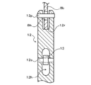
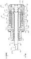
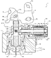
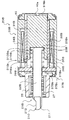
図1は、本発明の一実施例としてのパーキング装置1の構成の概略を示す構成図であり、図2は、パーキング装置1の要部の構成の概略を示す構成図であり、図3は、油圧ユニット10の一部の構成の概略を示す構成図であり、図4は、電磁ユニット20の構成の概略を示す構成図である。
FIG. 1 is a configuration diagram showing an outline of the configuration of a
実施例のパーキング装置1は、車両に搭載され、図示しない変速機のトランスミッションケースの内部または外部に配置される。そして、このパーキング装置1は、図示しないシフトレバーの操作位置(シフトレンジ)に応じて出力される電気信号に基づいて変速機のいずれかの回転軸のロックおよびロックの解除を行なう、いわゆるシフトバイワイヤ式のパーキング装置として構成されている。
The
パーキング装置1は、図1に示すように、複数の歯2aを有すると共に変速機のいずれかの回転軸に取り付けられるパーキングギヤ2と、パーキングギヤ2と係合可能な突部3aを有すると共に図示しないスプリングによりパーキングギヤ2から離間するよう付勢されるパーキングポール3と、進退移動可能なパーキングロッド4と、パーキングロッド4の軸方向に移動可能な筒状のカム部材5と、例えばトランスミッションケースにより回転自在に支持されてパーキングポール3と共にカム部材5を挟持する支持ローラ6と、パーキングロッド4により一端が支持されると共にパーキングポール3をパーキングギヤ2に押し付けるようにカム部材5を付勢するカムスプリング7と、パーキングロッド4に連結されたディテントレバー8と、ピストンロッド12の移動によりディテントレバー8を介してパーキングロッド4を進退移動させる油圧ユニット10と、ピストンロッド12の移動を規制することによりパーキングロッド4の進退移動を規制する電磁ユニット20と、を備える。このパーキング装置1では、図示するように、パーキングポール3の突部3aがパーキングギヤ2の隣り合う2つの歯2aの間の凹部と係合することにより、変速機の回転軸がロックされる(パーキングロックが行なわれる)。
As shown in FIG. 1, the
パーキングギヤ2やパーキングポール3,パーキングロッド4,カム部材5,支持ローラ6,カムスプリング7は、いずれも周知の構成を有する。ディテントレバー8は、略L字状に形成されており、第1遊端部8aと第2遊端部8bとを有する。第1遊端部8aは、パーキングロッド4の基端部(図1中右端部)に回転自在に連結されている。第2遊端部8bは、例えばトランスミッションケースにより支持される図示しないディテントスプリングに取り付けられた係合部材9と係合可能な係合凹部8rが形成されている。ディテントレバー8のコーナー部(第1,第2遊端部8a,8bの基端部)は、例えばトランスミッションケースにより支持された支軸8sにより回動自在に支持されている。
The parking gear 2, the
油圧ユニット10は、シフトレバーの操作位置(シフトレンジ)に応じて出力される電気信号に基づいて電子制御装置により制御される変速機の油圧制御装置からの油圧により動作するよう構成されている。この油圧ユニット10は、図2に示すように、複数の部材から構成されるケース11と、ディテントレバー8の第2遊端部8bに連結されると共にケース11により軸方向(図2中上下方向(第1方向))に移動自在に支持される移動部材としてのピストンロッド12と、ピストンロッド12に固定されると共にケース11に形成されたピストン室11p内に配置されるピストン14と、を備える。
The
ピストンロッド12は、先端部(図2中上端部)がケース11から外部に突出するようにケース11により支持されている。このピストンロッド12の先端部には、図3に示すように、先端側から基端側に向けて延びる連結凹部12rが形成されており、この連結凹部12rには、ディテントレバー8の第2遊端部8bが差し込まれている。ディテントレバー8には、連結凹部12r内に位置にするように長穴8hが形成されており、長穴8hには、ピストンロッド12の先端部により支持された連結ピン12pが挿通されている。長穴8hは、その内周と連結ピン12pの外周面との間に空間が画成されるよう形成されている。これにより、ピストンロッド12とディテントレバー8とは、互いにある程度の相対移動を許容するように連結される。
The
また、ピストンロッド12の軸方向の中央部付近には、ピストンロッド12を軸方向と直交する方向(図2中左右方向)に貫通すると共に軸方向に延在する穴部12hが形成されており、穴部12hの内部には、被当接部としてのローラ13が配置されている。ローラ13は、ローラベアリングとして構成されており、穴部12hの長手方向(図2,図3中上下方向)の長さより小さい外径を有する。このローラ13は、連結ピン12pと平行に延在するようにピストンロッド12によって支持される支持シャフト12sにより、穴部12h内で回転自在となるよう支持されている。
In addition, a
ピストン14は、ピストンロッド12の基端部(図2中下端部)に固定され、シール部材15を介してピストン室11pの内壁面によりピストンロッド12の軸方向に移動自在に支持されている。このピストン14は、ピストン室11pの内部を油室11fとスプリング室11sとに区画する。油室11fは、ピストンロッド12の先端部(図2中上端部)やディテントレバー8から離間するようにピストン室11pの図2中下側に画成され、ケース11に形成された油孔11hと連通する。油室11f内には、図示しない油路や油孔11hを介して油圧制御装置からの油圧(作動油)が供給される。また、スプリング室11sは、ピストンロッド12の先端部やディテントレバー8に近接するようにピストン室11pの図2中上側に画成される。スプリング室11sには、ケース11とピストン14との間に位置するように弾性部材としてのリターンスプリング16が配置され、ピストン14は、リターンスプリング16により、スプリング室11s側から油室11f側に向けて(図中下側に)付勢される。
The
こうして構成される油圧ユニット10は、組立状態(組立完了時の状態)で、ピストン14が、リターンスプリング16により図1中下向きに付勢されて油室11fの底部に最接近し、ピストンロッド12のケース11からの突出量が最小となる。これにより、ディテントレバー8を介してピストンロッド12に連結されたパーキングロッド4がパーキングポール3の基端部に最接近し、カムスプリング7により付勢されたカム部材5によってパーキングポール3がパーキングギヤ2と係合するように押圧され、変速機の回転軸がロックされる(パーキングロックが行なわれる)。
The
図1に示すように変速機の回転軸がロックされている状態(以下、適宜「パーキングロック状態」という)で、油圧制御装置からの油圧が油圧ユニット10の油室11fに供給されると、ピストン14は、油室11f内の油圧によりリターンスプリング16の弾性力(付勢力)に抗してピストンロッド12の移動方向(第1方向)における図1中上側(以下、適宜「ロック解除側」という)に移動する。これにより、ピストン14に固定されたピストンロッド12もロック解除側に移動し、それに伴ってディテントレバー8が支軸8sの周りに図1中時計回りに回動すると共にパーキングロッド4が図1中右側に移動する。そして、パーキングロッド4が図1中右側に移動することにより、カム部材5によるパーキングポール3の押圧が解除され、パーキングギヤ2とパーキングポール3との係合、即ち、変速機の回転軸のロックが解除される(パーキングロックが解除される)。したがって、車両の走行中に油圧制御装置からの油圧が油圧ユニット10の油室11fに供給されているときには、変速機の回転軸はロックされない(パーキングロックは行なわれない)。
When the hydraulic pressure from the hydraulic control device is supplied to the
また、パーキングロックが解除されている状態(以下、適宜「パーキングロック解除状態」という)で、油圧制御装置から油孔11hへの油圧の供給が断たれて油室11fから油孔11hを介して作動油が流出していくと、ピストン14は、リターンスプリング16の弾性力によりピストンロッド12の移動方向における図1中下側(以下、適宜「ロック側」という)に移動する。これにより、ピストン14に固定されたピストンロッド12もロック側に移動し、それに伴ってディテントレバー8が支軸8sの周りに図1中反時計回りに回動すると共にパーキングロッド4が図1中左側に移動する。そして、パーキングロッド4が図1中左側に移動することにより、カムスプリング7により付勢されたカム部材5によってパーキングポール3がパーキングギヤ2と係合するように押圧され、変速機の回転軸がロックされる(パーキングロックが行なわれる)。なお、ディテントレバー8の第2遊端部8bの係合凹部8rと係合部材9とが係合することにより、ディテントレバー8の支軸8s周りの回動が図示しないディテントスプリングによってある程度規制され、それにより、パーキングロッド4の移動もある程度規制される。
Further, in a state where the parking lock is released (hereinafter referred to as “parking lock released state” as appropriate), the hydraulic pressure supply from the hydraulic control device to the
電磁ユニット20は、例えばアイドルストップ等により車両のエンジンとエンジンにより駆動されるオイルポンプとが停止されるのに伴って油圧ユニット10の油室11fに供給される油圧が低下したときに、リターンスプリング16の弾性力(付勢力)によってピストンロッド12がロック側に移動するのを規制し、パーキングロック解除状態からパーキングロック状態に移行しないようにするために用いられる。
The
この電磁ユニット20は、図4に示すように、ピストンロッド12に設けられた被当接部としてのローラ13(図2参照)と当接可能な当接部210を先端部に有するロックシャフト21と、ロックシャフト21を軸方向(図4中左右方向(第2方向))に移動自在に支持するシャフトホルダ25と、弾性力や磁力によりロックシャフト21を軸方向に付勢する(移動させる)電磁部30と、を備える。
As shown in FIG. 4, the
ロックシャフト21は、ステンレスなどの非磁性体により形成されており、図4に示すように、一端部(先端部)に当接部210を有する小径部22と、小径部22から当接部210とは反対側に延出し且つ小径部22より大径の大径部23と、を有する。小径部22は、略円柱状に形成されており、その先端部に形成される当接部210は、二面幅形状を有するように成形されている。大径部23は、略円柱状に形成されている。
The
小径部22の当接部210は、ピストンロッド12の移動方向(図4中上下方向)におけるロック側(図中下側)に位置するロック側当接面211と、ピストンロッド12の移動方向におけるロック解除側(図中上側)に位置するロック解除側当接面212と、を有する。ロック側当接面211は、当接部210側から大径部23側に向かうにつれてロック側に近づく傾斜状に形成されており、具体的には、ローラ13の外周面の半径(曲率半径)より小さい曲率半径を有すると共にロック側に凸となる断面円弧状の曲面によって傾斜状に形成されている。ロック解除側当接面212は、ロックシャフト21の移動方向(図4中左右方向)に平行な平坦面に形成されている。
The
シャフトホルダ25は、図4に示すように、アルミニウムなどの非磁性体により略有底筒状に形成されており、電磁部30により保持されている。シャフトホルダ25の底部には、ロックシャフト21の小径部22が挿通される孔が形成されており、ロックシャフト21の小径部22の当接部210は、シャフトホルダ25から図中左側に突出している。また、シャフトホルダ25の内部には、小径部22の外周面を摺動自在に支持する直動軸受27が固定されている。このように直動軸受27によって小径部22を支持することにより、ロックシャフト21のガタつきを抑制しつつロックシャフト21を軸方向にスムーズに移動させることができる。
As shown in FIG. 4, the
電磁部30は、図4に示すように、ロックシャフト21の外周側に配置されてロックシャフト21と共に軸方向(図中左右方向)に移動するプランジャ31と、プランジャ31の外周側に配置されるコイル34と、シャフトホルダ25を保持すると共にロックシャフト21やプランジャ31などを収容するケースとして機能するヨーク35と、プランジャ31とコイル34との間にシャフトホルダ25側から順に配置されるコア36,非磁性体部材38,コア37と、ヨーク35の図中右端部に装着されたリヤキャップ40と、ロックシャフト21とリヤキャップ40との間に配置されると共に弾性力によりロックシャフト21(およびプランジャ31)をシャフトホルダ25側(図中左側)に付勢する弾性部材としてのスプリング39と、を備える。
As shown in FIG. 4, the
プランジャ31は、鉄などの磁性体により中空円筒状に形成されており、ロックシャフト21の小径部22の外径より若干(例えば、0.5mm〜1mm程度)大きく且つ大径部23の外径より小さい内径を有する小内径部32と、小内径部32から図中右側に延出し且つロックシャフト21の大径部23の外径より若干(例えば、0.5mm〜1mm程度)大きい内径を有する大内径部33と、を有する。このプランジャ31は、小内径部32がロックシャフト21の小径部22の大径部23側の一部を囲むと共に大内径部33が大径部23の小径部22側の一部を囲むように配置される。したがって、ロックシャフト21の小径部22や大径部23の外周面とプランジャ31の小内径部32や大内径部33の内周面との間には、所定のクリアランスが形成される。
The
また、プランジャ31のリヤキャップ40側の端部(図中右端部)の外周面には、テーパ部31tが形成されている。このテーパ部31tは、図中左側から図中右側に向けて先細となる(外径が小さくなる)よう形成されている。
A tapered
コイル34は、ケースとして機能するヨーク35に取り付けられる図示しないコネクタに接続される端子を有する。コイル34には、油圧制御装置を制御する電子制御装置や他の電子制御装置により制御される電源回路やコネクタを介して図示しない車両の補機バッテリから電流が印加される。
The
ヨーク35は、鉄などの磁性体により形成されており、略中空円筒状の円筒部35aと、円筒部35aの一端側(図中左端側)で径方向内側に段階的に突出する環状のフランジ部35b,35cと、を有する。フランジ部35bは、コイル34の内径と略同一の内径を有すると共にコア36の外径と略同一の内径を有し、コイル34のシャフトホルダ25側(図中左側)で径方向内側に突出している。フランジ部35cは、フランジ部35bのシャフトホルダ25側で径方向内側に突出しており、プランジャ31(小内径部32)のシャフトホルダ25側の端面31aと図中左右方向で対向している。このフランジ部35bのプランジャ31側(図中右側)には、突起部35dが形成されている。
The
コア36,37は、鉄などの磁性体により形成されている。コア36は、中空円筒状に形成されている。コア37は、コア36よりリヤキャップ40側(図中右側)に配置され、コア36と同一の内径および外径を有する中空円筒状に形成された円筒部37aと、円筒部37aの図中右端部で径方向内側,径方向外側に突出する環状の内側フランジ部37b,外側フランジ部37cと、を有する。このコア37は、円筒部37aが、ロックシャフト21およびプランジャ31が図中最左側の位置(プランジャ31のシャフトホルダ25側の端面31aがヨーク35のフランジ部35cの突起部35dに当接する位置すなわちロックシャフト21のシャフトホルダ25からの突出量が最大となる位置、以下、「突出量最大位置」という)に位置しているときのプランジャ31よりリヤキャップ40側となるよう配置される。
The
非磁性体部材38は、非磁性体により、コア36およびコア37の円筒部37aと同一の内径および外径を有する中空円筒状に形成されている。
The
こうして構成される電磁ユニット20は、組立状態(組立完了時の状態)すなわち油圧ユニット10に取り付けられる前の状態では、スプリング39の弾性力により、ロックシャフト21およびプランジャ31は、ロックシャフト21の大径部23の小径部22側の端面23aとプランジャ31の小内径部32の大内径部33側の端面32aとの当接によってロックシャフト21にプランジャ31が押圧されて一体となってシャフトホルダ25側(図4中左側)に付勢されており、突出量最大位置に位置する。
When the
そして、コイル34への通電時には、その通電に伴って発生する磁束(ヨーク35,コア36,プランジャ31,コア37,ヨーク35を通過する磁束)によってプランジャ31がコア37に吸引されることにより、ロックシャフト21およびプランジャ31は、小内径部32の大内径部33側の端面32aと大径部23の小径部22側の端面23aとの当接によってプランジャ31にロックシャフト21が押圧され、一体となってリヤキャップ40側(図4中右側)に移動する。なお、ヨーク35のフランジ部35cに突起部35dを設けた(プランジャ31とヨーク35との当接面積を小さくした)ことにより、磁束は、ヨーク35の円筒部35aとプランジャ31との間でフランジ部35b,コア36を経由しやすくなる(フランジ部35c,突起部35dを経由しにくくなる)から、磁路が長くなるのを抑制することができる。
When the
この電磁ユニット20では、ロックシャフト21の外周面とプランジャ31の内周面との間には、所定のクリアランスが形成されるから、ロックシャフト21が径方向にガタついたとしても、そのガタツキを所定のクリアランスによって吸収して、プランジャ31が径方向にガタつくのを抑制することができる。これにより、プランジャ31とコア36,37との間の磁気ギャップを小さくすることができる。また、ロックシャフト21が非磁性体により形成されているから、コイル34への通電時の磁束漏れを低減することができる。これらの結果、電磁部30ひいては電磁ユニット20ひいてはパーキング装置1の大型化を抑制しつつ磁気効率を高くすることができる。
In the
また、プランジャ31の図4中右端部の外周面にはテーパ部31tが形成されているから、コイル34への通電に伴って発生する磁束によってロックシャフト21およびプランジャ31が図4中右側に移動する際には、その移動に従って、プランジャ31とコア37(円筒部37a)との距離(空隙)が徐々に小さくなり、コア37によるプランジャ31に対する吸引力が徐々に大きくなる。ロックシャフト21およびプランジャ31が図4中右側に移動するのに従って、スプリング39の弾性力が徐々に大きくなるから、コア37によるプランジャ31に対する吸引力も徐々に大きくなるようにすることにより、ロックシャフト21およびプランジャ31を滑らかに図4中右側に移動させることができる。
Further, since the tapered
電磁ユニット20は、図1および図2に示すように、油圧ユニット10のピストンロッド12の軸方向(図中上下方向(図1の一点鎖線参照))と、ロックシャフト21およびプランジャ31の軸方向(図中左右方向(図1の二点差線参照))とが直交するよう、油圧ユニット10に取り付けられる。これにより、両者を同軸に配置する構成に比して、トランスミッションケースの内部または外部の限られたスペースに油圧ユニット10および電磁ユニット20を容易に配置することができる。特に、FF(フロントエンジンフロントドライブ)式の車両に搭載される場合に有用である。
As shown in FIGS. 1 and 2, the
電磁ユニット20が油圧ユニット10のケース11に取り付けられた際、ロックシャフト21の当接部210(ロック側当接面211およびロック解除側当接面212)は、ピストンロッド12の軸方向から見て(図2の上側または下側から見て)ローラ13の外周面の少なくとも一部と重なり合う。そして、実施例では、電磁ユニット20は、図2に示すように、ロックシャフト21の当接部210のロック側当接面211がローラ13の外周面と当接する(ロック側当接面211がローラ13から力を受ける)ように油圧ユニット10のケース11に取り付けられる。これにより、ロックシャフト21の当接部210(ロック側当接面211)には、ピストンロッド12のローラ13からロックシャフト21の軸方向の力(強制力)が作用し、それにより、電磁ユニット20のロックシャフト21および軸部材31がスプリング39の弾性力に抗してリヤキャップ40側(図中右側)に僅かに移動する。したがって、プランジャ31のシャフトホルダ25側(図中左側)の端面31aと、ヨーク35のフランジ部35cに設けられた突起部35dとの間に若干の隙間が形成される。
When the
次に、こうして構成された実施例のパーキング装置1および電磁ユニット20の動作について説明する。
Next, operations of the
油圧ユニット10の油室11fに油圧制御装置からの油圧(作動油)が供給されておらず且つ電磁ユニット20の電磁部30のコイル34に通電されていないときには、油圧ユニット10および電磁ユニット20は、図2に示す状態となっており、パーキング装置1により変速機の回転軸がロックされる(パーキングロックが行なわれる)。
When the hydraulic pressure (hydraulic fluid) from the hydraulic control device is not supplied to the
そして、車両の走行開始に際してパーキングロック状態からパーキングロック解除状態に移行させるときには、油圧制御装置からの油圧が油圧ユニット10の油室11fに供給される。なお、この際、コイル34への通電は行なわれない。
When shifting from the parking lock state to the parking lock release state when the vehicle starts to travel, the hydraulic pressure from the hydraulic control device is supplied to the
油圧制御装置からの油圧が油圧ユニット10の油室11fに供給されると、ピストン14およびピストンロッド12は、図5に示すように、油室11f内の油圧によりリターンスプリング16の弾性力に抗してロック解除側(図中上側)に移動する。上述したように、パーキングロック状態では、ローラ13がロックシャフト21の当接部210のロック側当接面211と当接しているから、ピストンロッド12がロック解除側に移動し始めると、ローラ13がロックシャフト21のロック側当接面211上を転動しながら、ピストンロッド12からロックシャフト21にローラ13とロック側当接面211との接線方向と直交する方向(法線方向)の力が作用する。そして、その法線方向の力により、ロックシャフト21とプランジャ31とは、スプリング39の弾性力に抗して一体となってリヤキャップ40側(図5中右側)に移動する。
When the hydraulic pressure from the hydraulic control device is supplied to the
そして、図5に示すように、ピストンロッド12のロック解除側への移動に伴ってローラ13がロックシャフト21のロック側当接面211から離れた後は、ロックシャフト21とプランジャ31とがスプリング39の弾性力により穴部12hの奥側(図5中左側)に移動しながら、ピストンロッド12は油圧により更にロック解除側に移動し、図6に示すように、ローラ13とロックシャフト21のロック解除側当接面212との間に所定の間隔が形成される位置で停止する。なお、ロックシャフト21およびプランジャ31は、スプリング39の弾性力により、突出量最大位置(プランジャ31の端面31aがヨーク35のフランジ部35cの突起部35dに当接する位置(図4参照))まで移動する。そして、この状態で、ロックシャフト21の当接部210のロック解除側当接面212は、ピストンロッド12の軸方向から見て、ピストンロッド12のローラ13の中央部と対向する(重なる)。
Then, as shown in FIG. 5, after the
このようにして、ピストンロッド12が油圧によりロック解除側への移動を開始してから停止するまでの間に、ディテントレバー8が支軸8sの周りに図1の時計回りに回動すると共に、パーキングロッド4が図1中右側に移動する。これにより、パーキングロッド4の移動に伴ってカム部材5によるパーキングポール3の押圧が解除され、パーキングロックが解除される。
In this way, the
実施例では、図2に示すパーキングロック状態で、ピストンロッド12のローラ13がロックシャフト21のロック側当接面211と当接している。これにより、パーキングロック状態でローラ13がロックシャフト21のロック側当接面211と当接しない構成に比して、ピストンロッド12の移動ストロークを小さくしてパーキング装置1のコンパクト化を図ることができる。また、パーキングロック状態からパーキングロック解除状態に速やかに移行させることができる。さらに、ピストンロッド12がロック側からロック解除側に移動する際にローラ13とロック側当接面211とが衝突しないようにして、ロックシャフト21やローラ13の耐久性を向上させると共にノイズの発生を抑制することができる。
In the embodiment, the
また、ピストンロッド12が油圧によりロック解除側に移動する際にローラ13からの力を受けるロック側当接面211は、ローラ13の外周面の半径(曲率半径)より小さい曲率半径を有している。これにより、ピストンロッド12がロック解除側に移動する際にローラ13からロックシャフト21に作用する軸方向の力(上述の法線方向の力の分力)をより大きくすることができるから、パーキングロックを解除する際に油圧ユニット10の油室11fに供給すべき油圧の上昇を抑制することができる。
Further, the lock-
さらに、被当接部としてのローラ13をピストンロッド12により回転自在に支持してロック側当接面211やロック解除側当接面212上を転動可能とすることにより、ローラ13とロック側当接面211やロック解除側当接面212との間の摩擦抵抗を低減させて両者の耐摩耗性(耐久性)を向上させることができる。
Further, the
図6に示すように、油圧によりピストンロッド12がロック解除側に移動してパーキングロックが解除された後、油圧制御装置からの油圧が油圧ユニット10の油室11fに供給されているときには、パーキングロック解除状態を維持することができる。実施例では、上述したように、油圧によりピストンロッド12がロック解除側に移動してパーキングロックが解除されているときには、ピストンロッド12のローラ13とロックシャフト21の当接部210のロック解除側当接面212とは互いに離間している。そして、ロックシャフト21の当接部210のロック解除側当接面212が、ピストンロッド12の軸方向から見て、ローラ13の中央部と対向している。
As shown in FIG. 6, when the hydraulic pressure from the hydraulic control device is supplied to the
図6に示すパーキングロック解除状態で、アイドルストップの実行等によるエンジンの停止に伴って油圧ユニット10の油室11fへの油圧が低下すると、リターンスプリング16の弾性力によりピストンロッド12がロック側に移動して、ピストンロッド12のローラ13とロックシャフト21の当接部210のロック解除側当接面212とが当接する。実施例では、上述したように、ロック解除側当接面212がロックシャフト21の移動方向に平行(ピストンロッド12のローラ13の移動方向に垂直)な平坦面に形成されているから、ローラ13とロック解除側当接面212とが当接したときに、ローラ13からロック解除側当接面212にロックシャフト21の移動方向の力は作用しない。これにより、ロックシャフト21がピストンロッド12から離間する側(図6中右側)に移動するのを抑制することができ、ピストンロッド12の図中下側すなわちロック側への移動を規制することができる。この結果、アイドルストップ等の実行により油圧ユニット10への油圧が低下したときでも、パーキングロック解除状態を保持することができる。しかも、この際にコイル34に通電する必要がないから、電力消費を抑制することができると共に何らかの事情によりコイル34に通電できないときでもパーキングロック解除状態を保持することができる。
When the oil pressure to the
また、パーキングロック解除状態で、コイル34への通電を開始すると、その通電に伴って発生する磁束によってプランジャ31がコア37に吸引されることにより、ロックシャフト21およびプランジャ31は、一体となって、スプリング39の弾性力に抗してリヤキャップ40側に移動する。このとき、ロックシャフト21は、その先端部がローラ13と図6中上下方向で重ならない位置(ピストンロッド12の図6中下方向の移動を規制しない位置)まで移動する。これにより、ピストンロッド12およびピストン14は、リターンスプリング16の弾性力により、ロック側に移動することができる状態となる。
Further, when energization of the
そして、コイル34に通電しながら油圧ユニット10の油室11fへの油圧が低下すると、油室11fから油孔11hを介して作動油が流出し、ピストン14およびピストンロッド12は、リターンスプリング16の弾性力により、図6中下側すなわちロック側に移動する。そして、ピストン14およびピストンロッド12が図2に示す位置で停止した後に、コイル34への通電を終了すると、ロックシャフト21およびプランジャ31がスプリング39の付勢力によって図6中左側に移動して図2に示す位置で停止する。
When the hydraulic pressure to the
このようにして、ピストンロッド12がリターンスプリング16の弾性力によりロック側への移動を開始してから停止するまでの間に、ディテントレバー8が支軸8sの周りに図1の反時計回りに回動すると共に、パーキングロッド4が図1中左側に移動する。これにより、パーキングロッド4の移動に伴ってカムスプリング7により付勢されたカム部材5によってパーキングポール3がパーキングギヤ2と係合するよう押圧され、パーキングロックが行なわれる。
In this way, the
以上説明した実施例のパーキング装置1では、電磁ユニット20のロックシャフト21およびプランジャ31の移動方向が油圧ユニット10のピストンロッド12の移動方向と直交するよう電磁ユニット20が配置される(油圧ユニット10に取り付けられる)。これにより、両者が同一方向に移動するよう配置されるものに比して、限られたスペースへの配置を良好なものとすることができる。
In the
また、実施例のパーキング装置1では、ロックシャフト21の当接部210のロック解除側当接面212がロックシャフト21の移動方向に平行な平坦面に形成されており、パーキングロック解除状態で、コイル34への非通電時には、スプリング39の弾性力により、ロックシャフト21およびプランジャ31がロック解除側当接面212がピストンロッド12のローラ13と当接可能となるようにピストンロッド12側に付勢される。したがって、ローラ13とロック解除側当接面212とが当接したときに、ロックシャフト21がロックシャフト21から離間する側に移動するのを抑制することができ、ピストンロッド12のロック側への移動を規制することができる。この結果、アイドルストップ等の実行により油圧ユニット10への油圧が低下したときでも、パーキングロック解除状態を保持することができる。しかも、この際にコイル34に通電する必要がないから、電力消費を抑制することができると共に、何らかの事情によりコイル34に通電できないときでもパーキングロック解除状態を保持することができる。
Further, in the
さらに、実施例のパーキング装置1では、パーキングロック解除状態で、コイル34への通電時には、その通電に伴って発生する磁束により、ロックシャフト21およびプランジャ31が、スプリング39の弾性力に抗して、ピストンロッド12から離間する側に、ロックシャフト21の先端部がピストンロッド12の軸方向から見てローラ13と重ならない位置まで移動する。これにより、ピストンロッド12のロック側への移動が許容される。
Furthermore, in the
加えて、実施例のパーキング装置1では、ロックシャフト21の外周面とプランジャ31の内周面との間には、所定のクリアランスが形成されるから、ロックシャフト21が径方向にガタついたとしても、プランジャ31が径方向にガタつくのを抑制することができ、プランジャ31とコア36との間の磁気ギャップを小さくすることができる。また、ロックシャフト21が非磁性体により形成されているから、コイル34への通電時の磁束漏れを低減することができる。これらの結果、電磁部30ひいては電磁ユニット20ひいてはパーキング装置1の大型化を抑制しつつ磁気効率を高くすることができる。
In addition, in the
また、実施例のパーキング装置1では、プランジャ31のリヤキャップ40側の端部の外周面にはテーパ部31tが形成されているから、コイル34への通電に伴って発生する磁束によってロックシャフト21およびプランジャ31がリヤキャップ40側に移動する際に、その移動を滑らかなものとすることができる。
Further, in the
実施例のパーキング装置1では、パーキングロック解除状態で、コイル34に通電しており油圧ユニット10の油室11fへの油圧が低下したときに、リターンスプリング16の弾性力により、ピストンロッド12がロック側に移動するものとしたが、このときに、図6の二点鎖線に示すように、油圧ユニット10のスプリング室11sに油圧制御装置からの油圧(作動油)を供給するものとしてもよい。こうすれば、ピストンロッド12をロック側により迅速に移動させることができる。
In the
実施例のパーキング装置1では、パーキングロック状態からパーキングロック解除状態に移行する際に、コイル34に通電せずにピストンロッド12を油圧によりロック解除側に移動させるものとしたが、コイル34に通電してロックシャフト21およびプランジャ31をピストンロッド12から離間する側に移動させながらまたは移動させてからピストンロッド12を油圧によりロック解除側に移動させるものとしてもよい。こうすれば、ピストンロッド12をロック解除側により低い油圧で移動させることができる。
In the
実施例のパーキング装置1では、プランジャ31のリヤキャップ40側の端部の外周面には、端面に向けて先細となる(外径が小さくなる)テーパ部31tが形成されるものとしたが、テーパ部31tが形成されず、外径が一定となるよう形成されるものとしてもよい。
In the
実施例のパーキング装置1では、ロックシャフト21の小径部22の当接部210のロック側当接面211は、ロック側に凸となる断面円弧状の曲面によって傾斜状に形成されるものとしたが、ロック側に凸となり円弧以外の断面形状の曲面によって傾斜状に形成されるものとしてもよいし、当接部210側から大径部23側に向かうにつれてロック側に一定角度で傾斜する(平坦な)斜面に形成されるものとしてもよい。
In the
実施例のパーキング装置1では、油圧ユニット10に電磁ユニット20が取り付けられた際において、ロックシャフト21の当接部210のロック側当接面211とローラ13の外周面とが当接して、プランジャ31の端面31aとヨーク35のフランジ部35cの突起部35dとの間に若干の隙間が形成されるものとしたが、プランジャ31の端面31aとヨーク35のフランジ部35cの突起部35dとが当接した状態となるものとしてもよい。この場合、ピストンロッド12のローラ13の外周面が、ロックシャフト21の当接部210のロック側当接面211からロック側に離間しているものとしてもよい。そして、ローラ13がロック側当接面211からロック側に離間しているものにおいて、コイル34に通電してロックシャフト21をその先端部がローラ13と図6中上下方向で重ならない位置まで移動させてからピストンロッド12を油圧によりロック解除側に移動させる場合、ローラ13からロック側当接面211に作用する力の図6中左右方向の分力によってロックシャフト21をピストンロッド12から離間する側に移動させる必要がないから、ロック側当接面211は、ロックシャフト21の移動方向(図4中左右方向)に平行な平坦面に形成されるものとしてもよい。
In the
実施例のパーキング装置1では、ロックシャフト21およびプランジャ31は、スプリング39の弾性力によってピストンロッド12側に付勢され、コイル34への通電に伴って発生する磁束によってピストンロッド12から離間する側に移動するものとしたが、弾性部材の弾性力によってピストンロッド12から離間する側に付勢され、コイルへの通電に伴って発生する磁束によってピストンロッド12側に移動するものとしてもよい。図7および図8は、変形例のパーキング装置1Bの要部の構成の概略を示す構成図であり、図9は、パーキング装置1Bの電磁ユニット20Bの構成の概略を示す構成図である。図7,図8は、それぞれ、パーキングロック解除状態で油圧ユニット10の油室11fに油圧が供給されており電磁ユニット20Bのコイル34Bに通電されていないとき,通電されているときの様子を示す。なお、この変形例では、パーキング装置1Bのうち電磁ユニット20B以外の構成については実施例と同様であることから、実施例と同一の符号を付し、その詳細な説明は省略する。また、電磁ユニット20Bの各構成要素のうち実施例と同様の構成要素についても、実施例と同一の符号を付し、その詳細な説明は省略する。
In the
変形例のパーキング装置1Bの電磁ユニット20Bは、図9に示すように、当接部210を先端部に有するロックシャフト21Bと、ロックシャフト21Bを軸方向(図9中左右方向)に移動自在に支持するシャフトホルダ25と、弾性力や磁力によりロックシャフト21Bを軸方向に付勢する(移動させる)電磁部30Bと、を備える。
As shown in FIG. 9, the
ロックシャフト21Bは、非磁性体により形成されており、一端部(先端部)に当接部210を有する小径部22Bと、小径部22Bから当接部210とは反対側に延出し且つ小径部22Bより大径の大径部23Bと、を有する。小径部22Bは、略円柱状に形成されており、その先端部に形成される当接部210は、ロック側当接面211とロック解除側当接面212とを有する。大径部23Bは、略円柱状に形成されており、小径部22B側とは反対側(図中右側)の円形の端面23Baを有する。
The
電磁部30Bは、軸方向(図中左右方向)に移動するプランジャ31Bと、プランジャ31Bの外周側に配置されるコイル34Bと、シャフトホルダ25を保持すると共にロックシャフト21Bやプランジャ31Bなどを収容するケースとして機能するヨーク35Bと、プランジャ31Bとコイル34Bとの間に図中右側から順に配置されるコア36B,非磁性体部材38B,コア37Bと、弾性力によりロックシャフト21B(およびプランジャ31B)をシャフトホルダ25側とは反対側(図中右側)に付勢するスプリング39Bと、ヨーク35の図中右端部に装着されたリヤキャップ40と、を備える。
The
プランジャ31Bは、磁性体により円筒状に形成されており、軸方向の一端側(図中左側)に形成された凹部310Bと、凹部310Bの周囲の平坦且つ環状の端面31Baと、軸方向の他端側の円形の端面31Bbと、を有する。凹部310Bには、その底面310Baにロックシャフト21の大径部23Bの端面23Baが当接するようにロックシャフト21が挿入される。凹部310Bの内径は、ロックシャフト21Bの大径部23Bの外径より若干(例えば、0.5mm〜1mm程度)大きく定められている。したがって、ロックシャフト21Bの外周面とプランジャ31Bの凹部310Bの内周面との間には、クリアランスが形成される。
The
また、プランジャ31Bの図中左端部の外周面には、テーパ部31Btが形成されている。このテーパ部31Btは、図中右側から図中左側に向けて先細となる(外径が小さくなる)よう形成されている。
A tapered portion 31Bt is formed on the outer peripheral surface of the left end portion of the
ヨーク35Bは、磁性体により略中空円筒状に形成されている。コア36Bは、磁性体により中空円筒状に形成されている。コア37Bは、磁性体により形成されると共にコア36よりシャフトホルダ25(図中左側)に配置されており、コア36Bと同一の内径および外径を有する中空円筒状に形成された円筒部37Baと、円筒部37Baの図中左端部で径方向内側,径方向外側に突出する内側フランジ部37Bb,外側フランジ部37Bcと、を有する。非磁性体部材37Bは、コア36Bおよびコア37Bの円筒部37Baと同一の内径および外径を有する中空円筒状に形成されている。
The
スプリング39Bは、ロックシャフト21の大径部23Bとヨーク35Bの内側フランジ部37Bbとの間に配置され、プランジャ31Bの凹部310Bに挿入されているロックシャフト21をプランジャ31Bと一体にリヤキャップ40側(図中右側)に付勢する。
The
こうして構成される電磁ユニット20Bは、その組立状態(組立完了時の状態)や油圧ユニット10に取り付けられた状態では、図7や図9から分かるように、スプリング39Bの弾性力により、ロックシャフト21Bおよびプランジャ31Bが一体となってシャフトホルダ25側とは反対側(図9中右側)に付勢されている。このとき、ロックシャフト21およびプランジャ31Bは、図中最右側の位置(プランジャ31Bの端面31Bbがリヤキャップ40の突起部40aに当接する位置すなわちロックシャフト21Bのシャフトホルダ25からの突出量が最小となる位置、以下、「突出量最小位置」という)に位置する。そして、この状態では、ロックシャフト21の先端部は、ローラ13と図7中上下方向で重ならない(ピストンロッド12の図7中上下方向の移動を規制しない)。
The
そして、コイル34Bへの通電時には、その通電に伴って発生する磁束(ヨーク35B,コア36B,プランジャ31B,コア37B,ヨーク35Bを通過する磁束)によってプランジャ31Bがコア37Bに吸引されることにより、ロックシャフト21Bおよびプランジャ31Bが一体となってピストンロッド12側(図8中左側)に移動する。このとき、図8から分かるように、ロックシャフト21Bの当接部210のロック解除側当接面212は、ピストンロッド12の軸方向から見て、ローラ13の中央部と対向する(重なる)。
When the
この電磁ユニット20Bでは、ロックシャフト21Bの外周面とプランジャ31Bの凹部310Bの内周面との間には、クリアランスが形成されるから、ロックシャフト21Bが径方向にガタついたとしても、そのガタツキを所定のクリアランスによって吸収して、プランジャ31Bが径方向にガタつくのを抑制することができる。これにより、プランジャ31Bとコア36B,37Bとの間の磁気ギャップを小さくすることができる。また、ロックシャフト21Bが非磁性体により形成されているから、コイル34Bへの通電時の磁束漏れを低減することができる。これらの結果、電磁部30Bひいては電磁ユニット20Bひいてはパーキング装置1Bの大型化を抑制しつつ磁気効率を高くすることができる。
In this
また、プランジャ31Bのピストンロッド12側の端部(図9中左端部)の外周面にはテーパ部31Btが形成されているから、コイル34Bへの通電に伴って発生する磁束によってロックシャフト21Bおよびプランジャ31Bがピストンロッド12側(図9中左側)に移動する際、その移動に従って、プランジャ31Bとコア37B(円筒部37Ba)との距離(空隙)が徐々に小さくなり、コア37Bによるプランジャ31Bに対する吸引力が徐々に大きくなる。ロックシャフト21Bおよびプランジャ31Bがピストンロッド12側に移動するのに従って、スプリング39Bの弾性力が徐々に大きくなるから、コア37Bによるプランジャ31Bに対する吸引力も徐々に大きくなるようにすることにより、ロックシャフト21Bおよびプランジャ31Bを滑らかにピストンロッド12側に移動させることができる。
Further, since the tapered portion 31Bt is formed on the outer peripheral surface of the end of the
この電磁ユニット20Bは、図7および図8に示すように、油圧ユニット10のピストンロッド12の軸方向(図中上下方向)と、ロックシャフト21Bおよびプランジャ31Bの軸方向(図中左右方向)とが直交するよう、油圧ユニット10に取り付けられる。これにより、両者を同軸に配置する構成に比して、トランスミッションケースの内部または外部の限られたスペースに油圧ユニット10および電磁ユニット20Bを容易に配置することができる。特に、FF(フロントエンジンフロントドライブ)式の車両に搭載される場合に有用である。
As shown in FIGS. 7 and 8, the
そして、この電磁ユニット20Bが用いられるパーキング装置1Bでは、コイル34Bへの非通電時には、スプリング39Bの弾性力によりロックシャフト21Bおよびプランジャ31Bが突出量最小位置に位置しており、ロックシャフト21Bの先端部がローラ13と図7中上下方向で重ならない(ピストンロッド12の図7中上下方向の移動を規制しない)。したがって、リターンスプリング16の弾性力またはそれに抗する油圧により、ピストンロッド12およびピストン14が図7中上下方向に移動することができ、パーキングロック状態とパーキングロック解除状態とを切り替えることができる。
In the
また、パーキングロック解除状態でコイル34Bに通電すると、図8に示すように、その通電に伴って発生する磁束によってプランジャ31Bがコア37Bに吸引され、ロックシャフト21Bおよびプランジャ31Bが一体となってピストンロッド12側(図8中左側)に移動し、ロックシャフト21Bの当接部210のロック解除側当接面212がピストンロッド12の軸方向から見てローラ13の中央部と対向する(重なる)。ロック解除側当接面212は、実施例と同様にロックシャフト21Bの移動方向(図8中左右方向)に平行な平坦面に形成されているから、油圧ユニット10の油室11fへの油圧が低下してリターンスプリング16の弾性力によりピストンロッド12がロック側に移動して、ピストンロッド12のローラ13とロック解除側当接面212とが当接したときには、ローラ13からロック解除側当接面212にロックシャフト21Bの移動方向の力は作用しない。これにより、ロックシャフト21Bがロックシャフト21Bから離間する側(図6中右側)に移動するのを抑制することができ、ピストンロッド12の図中下側すなわちロック側への移動を規制することができる。この結果、アイドルストップ等の実行により油圧ユニット10への油圧が低下したときでも、パーキングロック解除状態を保持することができる。
When the
この変形例のパーキング装置1Bでは、プランジャ31Bのピストンロッド12側の端部の外周面には、端面に向けて先細となる(外径が小さくなる)テーパ部31Btが形成されるものとしたが、テーパ部31Btが形成されず、外径が一定となるよう形成されるものとしてもよい。
In the
また、この変形例のパーキング装置1では、ロックシャフト21Bのロック側当接面211は、ロック側に凸となる断面円弧状の曲面に形成されるものとしたが、ロック側に凸となり円弧以外の断面形状の曲面に形成されるものとしてもよいし、当接部210側から大径部23B側に向かうにつれてロック側に一定角度で傾斜する(平坦な)斜面に形成されるものとしてもよい。また、この変形例では、コイル34Bへの非通電時にロックシャフト21Bの先端部がローラ13と図7中上下方向で重ならない(ピストンロッド12の移動を規制しない)から、ロック側当接面211は、ロックシャフト21Bの移動方向(図7中左右方向)に平行な平坦面に形成されるものとしてもよい。
In the
実施例や変形例のパーキング装置1,1Bでは、シャフトホルダ25の内部に固定されると共にロックシャフト21,21Bの小径部22,22Bの外周面を摺動自在に支持する直動軸受27を備えるものとしたが、この直動軸受27を備えないものとしてもよい。
The
実施例や変形例のパーキング装置1,1Bでは、ピストンロッド12の被当接部として、ピストンロッド12によって支持される支持シャフト12sにより回転自在に支持されるローラ13を用いるものとしたが、ピストンロッド12により回転自在に支持される円柱体を用いるものとしてもよいし、ピストンロッド12に対して回転不能に構成されるもの(例えば、支持シャフト12sと同様のもの)を用いるものとしてもよい。
In the
実施例や変形例のパーキング装置1,1Bでは、ロックシャフト21,21Bとプランジャ31,31Bとが別体として構成されるものとしたが、一体に構成されるものとしてもよい。
In the
実施例や変形例のパーキング装置1,1Bでは、ピストンロッド12は、リターンスプリング16の弾性力により図2中下側(ロック側)に付勢され、リターンスプリング16の弾性力に抗する油圧により図2中上側(ロック解除側)に移動するものとしたが、逆に、リターンスプリングの弾性力によりロック解除側に付勢され、そのリターンスプリングの弾性力に抗する油圧によりロック側に移動するものとしてもよい。
In the
次に、本発明のパーキング装置について説明する。 Next, the parking apparatus of the present invention will be described.
本発明のパーキング装置は、車両に搭載され、パーキングロック状態およびパーキングロック解除状態を形成するパーキング装置であって、第1方向に移動して前記パーキングロック状態と前記パーキングロック解除状態とを切替可能な第1移動部材と、弾性力により前記第1移動部材を前記第1方向の一方側に付勢する第1弾性部材とを有し、油圧により前記第1移動部材を前記第1方向の他方側に移動させる油圧ユニットと、少なくとも一部が磁性体により形成されると共に前記第1方向と直交する第2方向に移動する第2移動部材と、弾性力により前記第2移動部材を前記第2方向の一方側に付勢する第2弾性部材とを有し、前記コイルへの通電に伴って発生する磁束により前記第2移動部材を前記第2方向の他方側に移動させる電磁ユニットと、を備え、前記第2移動部材は、先端部に形成されて前記第1移動部材に設けられた被当接部と当接可能な当接部を有し、前記当接部は、前記第1弾性部材の弾性力により前記第1移動部材が前記第1方向の一方側に移動する際に前記被当接部と当接したときに該被当接部から力を受ける第1当接面を有し、前記第1当接面は、前記第2方向に平行となるよう形成されている、ことを特徴とする。 A parking device according to the present invention is mounted on a vehicle and forms a parking lock state and a parking lock release state. The parking device moves in a first direction and can switch between the parking lock state and the parking lock release state. A first moving member, and a first elastic member that urges the first moving member toward one side in the first direction by an elastic force, and the first moving member is moved in the other direction in the first direction by hydraulic pressure. A hydraulic unit that moves to the side, a second moving member that is formed of a magnetic material and moves in a second direction orthogonal to the first direction, and the second moving member is moved to the second by elastic force. A second elastic member biased to one side of the direction, and an electromagnetic for moving the second moving member to the other side of the second direction by a magnetic flux generated by energization of the coil Knit, and the second moving member has a contact portion that is formed at a distal end portion and can be brought into contact with a contacted portion provided on the first moving member. When the first moving member moves to one side in the first direction due to the elastic force of the first elastic member, the first contact receives a force from the abutted portion when it abuts on the abutted portion. It has a contact surface, and the first contact surface is formed to be parallel to the second direction.
この本発明のパーキング装置では、油圧ユニットの第1移動部材の移動方向(第1方向)と電磁ユニットの第2移動部材の移動方向(第2方向)とが直交するように油圧ユニットと電磁ユニットとが配置される。したがって、第1移動部材の移動方向と電磁ユニットの第2移動部材の移動方向とが同一方向となるように油圧ユニットと電磁ユニットとが配置されるものに比して、限られたスペースへの配置を良好なものとすることができる。 In the parking device of the present invention, the hydraulic unit and the electromagnetic unit are arranged such that the moving direction (first direction) of the first moving member of the hydraulic unit and the moving direction (second direction) of the second moving member of the electromagnetic unit are orthogonal to each other. And are arranged. Therefore, compared to the arrangement in which the hydraulic unit and the electromagnetic unit are arranged so that the moving direction of the first moving member and the moving direction of the second moving member of the electromagnetic unit are the same, The arrangement can be made favorable.
また、第2移動部材は、第2弾性部材の弾性力により第2方向の一方側に付勢されると共にコイルへの通電に伴って発生する磁束により第2方向の他方側に移動する。そして、第2移動部材は、先端部に形成されて移動部材に設けられた被当接部と当接可能な当接部を有し、その当接部は、第1弾性部材の弾性力により第1移動部材が第1方向の一方側に移動する際に被当接部と当接したときに被当接部から力を受ける第1当接面を有し、その第1当接面は、第2方向に平行となるよう形成されている。 The second moving member is urged to one side in the second direction by the elastic force of the second elastic member and moves to the other side in the second direction by the magnetic flux generated when the coil is energized. The second moving member has a contact portion that is formed at the distal end portion and can contact the contacted portion provided on the moving member, and the contact portion is caused by the elastic force of the first elastic member. When the first moving member moves to one side in the first direction, the first moving member has a first contact surface that receives a force from the contacted portion when the first moving member contacts the contacted portion, and the first contact surface is , Formed so as to be parallel to the second direction.
したがって、第1弾性部材の弾性力により第1移動部材が第1方向の一方側に移動する際に、第2弾性部材の弾性力またはコイルへの通電に伴って発生する磁束によって第2移動部材を第1移動部材側に付勢する(移動させる)ことにより、第1移動部材の被当接部と第2移動部材の当接部とが当接したときに被当接部から当接部に第2方向の力が作用しないから、第2移動部材が第1移動部材側とは反対側に移動する(第1移動部材から離間する)のを抑制することができる。この結果、第1移動部材の第1方向の一方側への移動を規制することができる。 Therefore, when the first moving member moves to one side in the first direction by the elastic force of the first elastic member, the second moving member is generated by the elastic force of the second elastic member or the magnetic flux generated by energization of the coil. By urging (moving) the first moving member toward the first moving member side, when the abutted portion of the first moving member abuts on the abutting portion of the second moving member, the abutting portion is moved from the abutted portion. Since the force in the second direction does not act on the second moving member, it is possible to prevent the second moving member from moving to the side opposite to the first moving member (separated from the first moving member). As a result, the movement of the first moving member to one side in the first direction can be restricted.
一方、第1弾性部材の弾性力により第1移動部材が第1方向の一方側に移動する際に、コイルへの通電に伴って発生する磁束または第2弾性部材の弾性力によって第2移動部材を第1移動部材側とは反対側に付勢する(移動させる)ことにより、第1移動部材の第1方向の移動を許容することができる。 On the other hand, when the first moving member moves to one side in the first direction by the elastic force of the first elastic member, the second moving member is generated by the magnetic flux generated by energization of the coil or the elastic force of the second elastic member. By urging (moving) the first moving member to the opposite side to the first moving member side, it is possible to allow the first moving member to move in the first direction.
こうした本発明のパーキング装置において、前記第2弾性部材は、弾性力により前記第2移動部材を前記第1移動部材側に付勢し、前記電磁ユニットは、前記コイルへの通電に伴って発生する磁束により前記第2移動部材を前記第1移動部材側とは反対側に移動させる、ものとすることもできる。こうすれば、コイルに通電せずに、第1弾性部材の弾性力による第1移動部材が第1方向の一方側への移動を規制することができるから、電力消費を抑制することができる。 In such a parking apparatus of the present invention, the second elastic member urges the second moving member toward the first moving member by an elastic force, and the electromagnetic unit is generated when the coil is energized. The second moving member may be moved to the side opposite to the first moving member side by magnetic flux. If it carries out like this, since the 1st moving member by the elastic force of the 1st elastic member can regulate movement to the one side of the 1st direction, without supplying electricity to a coil, power consumption can be controlled.
この第2弾性部材が弾性力により第2移動部材を第1移動部材側に付勢すると共に電磁ユニットがコイルへの通電に伴って発生する磁束により第2移動部材を第1移動部材側とは反対側に移動させる態様の本発明のパーキング装置において、前記第1移動部材は、非磁性体により形成されたシャフトと、磁性体により形成されたプランジャとを有し、前記プランジャは、前記シャフトの外周を囲むように配置されると共に該シャフトと一体に前記第2方向に移動する、ものとすることもできる。こうすれば、シャフトが径方向にガタついたとしても、そのガタツキをシャフトとプランジャとの間のクリアランス(隙間)で吸収することができるから、プランジャの外周に形成される磁気ギャップを小さくすることができる。また、シャフトが非磁性体により形成されるから、磁気ユニットでの磁束の漏れを低減することができる。これらの結果、磁気ユニットの大型化を抑制しつつ磁気効率を高くすることができる。 The second elastic member urges the second moving member toward the first moving member by the elastic force, and the second moving member is referred to as the first moving member by the magnetic flux generated when the electromagnetic unit energizes the coil. In the parking apparatus according to the aspect of the present invention, the first moving member includes a shaft formed of a non-magnetic material and a plunger formed of a magnetic material, and the plunger is connected to the shaft of the shaft. It may be arranged so as to surround the outer periphery and move in the second direction integrally with the shaft. In this way, even if the shaft is loose in the radial direction, the backlash can be absorbed by the clearance (gap) between the shaft and the plunger, so the magnetic gap formed on the outer periphery of the plunger can be reduced. Can do. Moreover, since the shaft is formed of a nonmagnetic material, leakage of magnetic flux in the magnetic unit can be reduced. As a result, the magnetic efficiency can be increased while suppressing an increase in the size of the magnetic unit.
この第1移動部材がシャフトとプランジャとを有する態様の本発明のパーキング装置において、前記シャフトは、前記当接部を有する小径部と、該小径部の前記当接部とは反対側で該小径部より大径の大径部とを有し、前記プランジャは、前記小径部の外径より大きく前記大径部の外径より小さな内径の小内径部を有し、前記シャフトと前記プランジャとは、前記第1弾性部材の弾性力により、前記大径部によって前記小内径部が押圧されて前記第1移動部材側に付勢され、前記コイルへの通電に伴って発生する磁束により、前記小内径部によって前記大径部が押圧されて前記第1移動部材側とは反対側に付勢される、ものとすることもできる。 In the parking apparatus of the present invention in which the first moving member has a shaft and a plunger, the shaft has a small diameter portion having the contact portion, and the small diameter portion on the side opposite to the contact portion of the small diameter portion. A large-diameter portion having a larger diameter than the portion, and the plunger has a small inner diameter portion having an inner diameter larger than the outer diameter of the small-diameter portion and smaller than the outer diameter of the large-diameter portion, and the shaft and the plunger The small inner diameter portion is pressed by the large diameter portion by the elastic force of the first elastic member and urged toward the first moving member, and the small magnetic flux is generated by the magnetic flux generated when the coil is energized. The large-diameter portion may be pressed by the inner-diameter portion and urged to the opposite side to the first moving member side.
また、第1移動部材がシャフトとプランジャとを有する態様の本発明のパーキング装置において、前記プランジャの前記第1移動部材側とは反対側の端部の外周面には、テーパ部が形成されている、ものとすることもできる。こうすれば、コイルへの通電に伴って発生する磁束によってプランジャが第2方向の第1移動部材側とは反対側に移動する際に、その移動に従ってプランジャの外周に形成される磁気ギャップが小さくなり、プランジャに対する吸引力を徐々に大きくすることができる。プランジャのこの移動に従って第2弾性部材の弾性力も徐々に大きくなることから、このようにすることにより、シャフトおよびプランジャを滑らかに移動させることができる。 In the parking apparatus of the present invention in which the first moving member has a shaft and a plunger, a tapered portion is formed on the outer peripheral surface of the end of the plunger opposite to the first moving member. It can also be. In this way, when the plunger moves to the side opposite to the first moving member side in the second direction due to the magnetic flux generated by energizing the coil, the magnetic gap formed on the outer periphery of the plunger according to the movement becomes small. Thus, the suction force to the plunger can be gradually increased. Since the elastic force of the second elastic member gradually increases as the plunger moves, the shaft and the plunger can be smoothly moved in this way.
第2弾性部材が弾性力により第2移動部材を第1移動部材側に付勢すると共に電磁ユニットがコイルへの通電に伴って発生する磁束により第2移動部材を第1移動部材側とは反対側に移動させる態様の本発明のパーキング装置において、前記第1移動部材には、前記当接部が進入可能で且つ前記第1移動部材を貫通する穴部が形成されており、前記当接部は、前記被当接部が前記当接部より前記第1方向の他方側に位置しており且つ前記コイルへの非通電時に、前記穴部内における前記被当接部と当接可能な位置に位置する、ものとすることもできる。 The second elastic member urges the second moving member toward the first moving member by the elastic force, and the second moving member is opposite to the first moving member due to the magnetic flux generated when the electromagnetic unit energizes the coil. In the parking apparatus according to the aspect of the present invention, the first moving member is formed with a hole through which the contact portion can enter and penetrates the first moving member. Is in a position where the abutted portion is located on the other side of the first direction from the abutting portion and can be abutted with the abutted portion in the hole portion when the coil is not energized. It can also be located.
本発明のパーキング装置において、前記当接部は、前記第1移動部材が前記第1方向の他方側に移動する際に前記被当接部と当接したときに該被当接部から力を受ける第2当接面を有し、前記第2当接面は、前記第2移動部材の先端部側から基端部側に向かうにつれて前記第1方向の一方側に近づく傾斜状に形成されている、ものとすることもできる。こうすれば、第1移動部材が第1方向の他方側(油圧により移動する側)に移動する際における第1移動部材の被当接部と第2移動部材の当接部との当接時に、第1移動部材から第2移動部材に作用する力の第2方向の分力により、第2移動部材を第1移動部材から離間する側に移動させることができる。 In the parking apparatus according to the aspect of the invention, the contact portion may be configured to apply a force from the contacted portion when the first moving member contacts the contacted portion when moving to the other side in the first direction. A second abutting surface that receives the second abutting surface, and the second abutting surface is formed in an inclined shape that approaches one side in the first direction from the distal end side toward the proximal end side of the second moving member. It can also be. If it carries out like this, when the 1st moving member moves to the other side (side moved by oil pressure) of the 1st direction, the contacted part of the 1st moving member and the contact part of the 2nd moving member will contact The second moving member can be moved away from the first moving member by the component force in the second direction of the force acting on the second moving member from the first moving member.
また、本発明のパーキング装置において、前記被当接部は、前記第1移動部材に対して回転可能なローラとして構成されている、ものとすることもできる。こうすれば、移動部材の被当接部と移動規制部材の当接部との間の摩擦抵抗を低減することができる。 Moreover, the parking apparatus of this invention WHEREIN: The said to-be-contacted part shall be comprised as a roller rotatable with respect to a said 1st moving member. If it carries out like this, the frictional resistance between the to-be-contacted part of a moving member and the contact part of a movement control member can be reduced.
さらに、本発明のパーキング装置において、前記第1弾性部材は、弾性力により前記第1移動部材を前記パーキングロックが形成されるロック側に付勢し、前記油圧ユニットは、油圧により前記第1移動部材を前記パーキングロックが解除されるロック解除側に移動させる、ものとすることもできる。 Furthermore, in the parking apparatus of the present invention, the first elastic member urges the first moving member toward a lock side on which the parking lock is formed by an elastic force, and the hydraulic unit moves the first movement by hydraulic pressure. The member may be moved to the unlocking side where the parking lock is released.
次に、実施例の主要な要素と課題を解決するための手段の欄に記載した発明の主要な要素との対応関係について説明する。実施例では、ピストンロッド12が「第1移動部材」に相当し、リターンスプリング16が「第1弾性部材」に相当し、油圧ユニット10が「油圧ユニット」に相当し、ロックシャフト21が「第2移動部材」に相当し、スプリング39が「第2弾性部材」に相当し、電磁ユニット20が「電磁ユニット」に相当する。
Next, the correspondence between the main elements of the embodiment and the main elements of the invention described in the column of means for solving the problems will be described. In the embodiment, the
なお、実施例の主要な要素と課題を解決するための手段の欄に記載した発明の主要な要素との対応関係は、実施例が課題を解決するための手段の欄に記載した発明を実施するための形態を具体的に説明するための一例であることから、課題を解決するための手段の欄に記載した発明の要素を限定するものではない。即ち、課題を解決するための手段の欄に記載した発明についての解釈はその欄の記載に基づいて行なわれるべきものであり、実施例は課題を解決するための手段の欄に記載した発明の具体的な一例に過ぎないものである。 The correspondence between the main elements of the embodiment and the main elements of the invention described in the column of means for solving the problem is the same as that of the embodiment described in the column of means for solving the problem. Therefore, the elements of the invention described in the column of means for solving the problems are not limited. That is, the interpretation of the invention described in the column of means for solving the problems should be made based on the description of the column, and the examples are those of the invention described in the column of means for solving the problems. It is only a specific example.
以上、本発明を実施するための形態について実施例を用いて説明したが、本発明はこうした実施例に何等限定されるものではなく、本発明の要旨を逸脱しない範囲内において、種々なる形態で実施し得ることは勿論である。 As mentioned above, although the form for implementing this invention was demonstrated using the Example, this invention is not limited at all to such an Example, In the range which does not deviate from the summary of this invention, it is with various forms. Of course, it can be implemented.
本発明は、パーキング装置の製造産業などに利用可能である。 The present invention can be used in the parking device manufacturing industry.
1,1B パーキング装置、2 パーキングギヤ、2a 歯、3 パーキングポール、3a 突部、4 パーキングロッド、5 カム部材、6 支持ローラ、7 カムスプリング、8 ディテントレバー、8a 第1遊端部、8b 第2遊端部、8h 長穴、8r 係合凹部、8s 支軸、9 係合部材、10 油圧ユニット、11 ケース、11f 油室、11h 油孔、11p ピストン室、11s スプリング室、12 ピストンロッド、12h 穴部、12p 連結ピン、12r 連結凹部、12s 支持シャフト、13 ローラ、14 ピストン、15 シール部材、16 リターンスプリング、20,20B 電磁ユニット、21,21B ロックシャフト、210 当接部、211 ロック側当接面、212 ロック解除側当接面、22,22B 小径部、23,23B 大径部、23a,23Ba 端面、25 シャフトホルダ、27 直動軸受、30,30B 電磁部、31,31B プランジャ、31a,32a,31Ba,31Bb 端面、31t,31Bt テーパ部、310B 凹部、310Ba 底面、32 小内径部、33 大内径部、34 34B コイル、35,35B ヨーク、35a 円筒部、35b,35c フランジ部、35d 突起部、36,36B,37,37B コア、37a,37Ba 円筒部、37b,37Bb 内側フランジ部、37c,37Bc 外側フランジ部、38,38B 非磁性体部材、39,39B スプリング、40 リヤキャップ、40a 突起部。 1, 1B parking device, 2 parking gear, 2a teeth, 3 parking pole, 3a protrusion, 4 parking rod, 5 cam member, 6 support roller, 7 cam spring, 8 detent lever, 8a first free end, 8b first 2 free end, 8h long hole, 8r engaging recess, 8s support shaft, 9 engaging member, 10 hydraulic unit, 11 case, 11f oil chamber, 11h oil hole, 11p piston chamber, 11s spring chamber, 12 piston rod, 12h Hole, 12p Connection pin, 12r Connection recess, 12s Support shaft, 13 Roller, 14 Piston, 15 Seal member, 16 Return spring, 20, 20B Electromagnetic unit, 21, 21B Lock shaft, 210 Contact part, 211 Lock side Contact surface, 212 Lock release side contact surface, 22, 22B Small diameter , 23, 23B Large diameter part, 23a, 23Ba end face, 25 shaft holder, 27 linear motion bearing, 30, 30B electromagnetic part, 31, 31B plunger, 31a, 32a, 31Ba, 31Bb end face, 31t, 31Bt taper part, 310B concave part , 310Ba bottom surface, 32 small inner diameter portion, 33 large inner diameter portion, 34 34B coil, 35, 35B yoke, 35a cylindrical portion, 35b, 35c flange portion, 35d protrusion, 36, 36B, 37, 37B core, 37a, 37Ba cylinder Part, 37b, 37Bb inner flange part, 37c, 37Bc outer flange part, 38, 38B non-magnetic member, 39, 39B spring, 40 rear cap, 40a protrusion.
Claims (9)
第1方向に移動して前記パーキングロック状態と前記パーキングロック解除状態とを切替可能な第1移動部材と、弾性力により前記第1移動部材を前記第1方向の一方側に付勢する第1弾性部材とを有し、油圧により前記第1移動部材を前記第1方向の他方側に移動させる油圧ユニットと、
少なくとも一部が磁性体により形成されると共に前記第1方向と直交する第2方向に移動する第2移動部材と、弾性力により前記第2移動部材を前記第2方向の一方側に付勢する第2弾性部材とを有し、前記コイルへの通電に伴って発生する磁束により前記第2移動部材を前記第2方向の他方側に移動させる電磁ユニットと、
を備え、
前記第2移動部材は、先端部に形成されて前記第1移動部材に設けられた被当接部と当接可能な当接部を有し、
前記当接部は、前記第1弾性部材の弾性力により前記第1移動部材が前記第1方向の一方側に移動する際に前記被当接部と当接したときに該被当接部から力を受ける第1当接面を有し、
前記第1当接面は、前記第2方向に平行となるよう形成されている、
ことを特徴とするパーキング装置。 A parking device mounted on a vehicle and forming a parking lock state and a parking lock release state,
A first moving member capable of moving in a first direction to switch between the parking lock state and the parking lock released state; and a first member that biases the first moving member to one side in the first direction by an elastic force. A hydraulic unit having an elastic member and moving the first moving member to the other side in the first direction by hydraulic pressure;
A second moving member that is at least partially formed of a magnetic material and moves in a second direction orthogonal to the first direction, and biases the second moving member to one side in the second direction by an elastic force. An electromagnetic unit having a second elastic member, and moving the second moving member to the other side in the second direction by a magnetic flux generated with energization of the coil;
With
The second moving member has a contact portion that is formed at a distal end portion and is capable of contacting a contacted portion provided on the first moving member,
When the first moving member moves to one side in the first direction by the elastic force of the first elastic member, the abutting portion is separated from the abutted portion when the abutting portion abuts on the abutted portion. A first abutment surface for receiving force,
The first contact surface is formed to be parallel to the second direction.
The parking apparatus characterized by the above-mentioned.
前記第2弾性部材は、弾性力により前記第2移動部材を前記第1移動部材側に付勢し、
前記電磁ユニットは、前記コイルへの通電に伴って発生する磁束により前記第2移動部材を前記第1移動部材側とは反対側に移動させる、
ことを特徴とするパーキング装置。 The parking device according to claim 1,
The second elastic member biases the second moving member toward the first moving member by an elastic force,
The electromagnetic unit moves the second moving member to a side opposite to the first moving member by a magnetic flux generated by energizing the coil;
The parking apparatus characterized by the above-mentioned.
前記第1移動部材は、非磁性体により形成されたシャフトと、磁性体により形成されたプランジャとを有し、
前記プランジャは、前記シャフトの外周を囲むように配置されると共に該シャフトと一体に前記第2方向に移動する、
ことを特徴とするパーキング装置。 The parking device according to claim 2,
The first moving member has a shaft formed of a nonmagnetic material and a plunger formed of a magnetic material,
The plunger is disposed so as to surround the outer periphery of the shaft and moves in the second direction integrally with the shaft.
The parking apparatus characterized by the above-mentioned.
前記シャフトは、前記当接部を有する小径部と、該小径部の前記当接部とは反対側で該小径部より大径の大径部とを有し、
前記プランジャは、前記小径部の外径より大きく前記大径部の外径より小さな内径の小内径部を有し、
前記シャフトと前記プランジャとは、前記第1弾性部材の弾性力により、前記大径部によって前記小内径部が押圧されて前記第1移動部材側に付勢され、前記コイルへの通電に伴って発生する磁束により、前記小内径部によって前記大径部が押圧されて前記第1移動部材側とは反対側に付勢される、
ことを特徴とするパーキング装置。 The parking device according to claim 3, wherein
The shaft has a small-diameter portion having the abutting portion, and a large-diameter portion having a larger diameter than the small-diameter portion on the side opposite to the abutting portion of the small-diameter portion,
The plunger has a small inner diameter portion having an inner diameter larger than the outer diameter of the small diameter portion and smaller than the outer diameter of the large diameter portion,
The shaft and the plunger are urged toward the first moving member by the small-diameter portion being pressed by the large-diameter portion by the elastic force of the first elastic member, and with energization to the coil The large-diameter portion is pressed by the small-diameter portion by the generated magnetic flux and is urged to the opposite side to the first moving member side.
The parking apparatus characterized by the above-mentioned.
前記プランジャの前記第1移動部材側とは反対側の端部の外周面には、テーパ部が形成されている、
ことを特徴とするパーキング装置。 The parking device according to claim 3 or 4,
A taper portion is formed on the outer peripheral surface of the end portion of the plunger opposite to the first moving member side,
The parking apparatus characterized by the above-mentioned.
前記第1移動部材には、前記当接部が進入可能で且つ前記第1移動部材を貫通する穴部が形成されており、
前記当接部は、前記被当接部が前記当接部より前記第1方向の他方側に位置しており且つ前記コイルへの非通電時に、前記穴部内における前記被当接部と当接可能な位置に位置する、
ことを特徴とするパーキング装置。 The parking device according to any one of claims 2 to 5,
The first moving member is formed with a hole through which the contact portion can enter and penetrate the first moving member.
The contact part is in contact with the contacted part in the hole when the contacted part is located on the other side in the first direction from the contact part and the coil is not energized. Located in a possible position,
The parking apparatus characterized by the above-mentioned.
前記当接部は、前記第1移動部材が前記第1方向の他方側に移動する際に前記被当接部と当接したときに該被当接部から力を受ける第2当接面を有し、
前記第2当接面は、前記第2移動部材の先端部側から基端部側に向かうにつれて前記第1方向の一方側に近づく傾斜状に形成されている、
ことを特徴とするパーキング装置。 The parking device according to any one of claims 1 to 6,
The contact portion has a second contact surface that receives a force from the contacted portion when the first moving member contacts the contacted portion when moving to the other side in the first direction. Have
The second contact surface is formed in an inclined shape that approaches one side in the first direction from the distal end side to the proximal end side of the second moving member.
The parking apparatus characterized by the above-mentioned.
前記被当接部は、前記第1移動部材に対して回転可能なローラとして構成されている、
ことを特徴とするパーキング装置。 The parking device according to any one of claims 1 to 7,
The abutted portion is configured as a roller that is rotatable with respect to the first moving member.
The parking apparatus characterized by the above-mentioned.
前記第1弾性部材は、弾性力により前記第1移動部材を前記パーキングロックが形成されるロック側に付勢し、
前記油圧ユニットは、油圧により前記第1移動部材を前記パーキングロックが解除されるロック解除側に移動させる、
ことを特徴とするパーキング装置。 The parking device according to any one of claims 1 to 8,
The first elastic member urges the first moving member to a lock side where the parking lock is formed by an elastic force,
The hydraulic unit moves the first moving member to a lock release side where the parking lock is released by hydraulic pressure;
The parking apparatus characterized by the above-mentioned.
Priority Applications (1)
| Application Number | Priority Date | Filing Date | Title |
|---|---|---|---|
| JP2013242883A JP2015102157A (en) | 2013-11-25 | 2013-11-25 | Parking device |
Applications Claiming Priority (1)
| Application Number | Priority Date | Filing Date | Title |
|---|---|---|---|
| JP2013242883A JP2015102157A (en) | 2013-11-25 | 2013-11-25 | Parking device |
Publications (1)
| Publication Number | Publication Date |
|---|---|
| JP2015102157A true JP2015102157A (en) | 2015-06-04 |
Family
ID=53378025
Family Applications (1)
| Application Number | Title | Priority Date | Filing Date |
|---|---|---|---|
| JP2013242883A Pending JP2015102157A (en) | 2013-11-25 | 2013-11-25 | Parking device |
Country Status (1)
| Country | Link |
|---|---|
| JP (1) | JP2015102157A (en) |
Cited By (5)
| Publication number | Priority date | Publication date | Assignee | Title |
|---|---|---|---|---|
| CN106438601A (en) * | 2016-09-09 | 2017-02-22 | 湖北三江航天红林探控有限公司 | Self-locking electromagnetic control device |
| JP2017101752A (en) * | 2015-12-02 | 2017-06-08 | ジヤトコ株式会社 | Parking mechanism |
| JP2020004844A (en) * | 2018-06-28 | 2020-01-09 | 日本電産トーソク株式会社 | Solenoid device |
| CN116576251A (en) * | 2023-05-23 | 2023-08-11 | 奇瑞汽车股份有限公司 | car parking lock system and car |
| WO2025124500A1 (en) * | 2023-12-13 | 2025-06-19 | 芜湖伯特利汽车安全系统股份有限公司 | Locking mechanism, control method of locking mechanism, motor gear unit, and vehicle |
-
2013
- 2013-11-25 JP JP2013242883A patent/JP2015102157A/en active Pending
Cited By (5)
| Publication number | Priority date | Publication date | Assignee | Title |
|---|---|---|---|---|
| JP2017101752A (en) * | 2015-12-02 | 2017-06-08 | ジヤトコ株式会社 | Parking mechanism |
| CN106438601A (en) * | 2016-09-09 | 2017-02-22 | 湖北三江航天红林探控有限公司 | Self-locking electromagnetic control device |
| JP2020004844A (en) * | 2018-06-28 | 2020-01-09 | 日本電産トーソク株式会社 | Solenoid device |
| CN116576251A (en) * | 2023-05-23 | 2023-08-11 | 奇瑞汽车股份有限公司 | car parking lock system and car |
| WO2025124500A1 (en) * | 2023-12-13 | 2025-06-19 | 芜湖伯特利汽车安全系统股份有限公司 | Locking mechanism, control method of locking mechanism, motor gear unit, and vehicle |
Similar Documents
| Publication | Publication Date | Title |
|---|---|---|
| JP6103056B2 (en) | Parking device | |
| JP6032361B2 (en) | Parking device | |
| JP6103057B2 (en) | Parking device | |
| JP6288102B2 (en) | Parking device | |
| JP6015570B2 (en) | Electromagnetic lock device and parking lock device having the same | |
| JP2015102157A (en) | Parking device | |
| WO2016031575A1 (en) | Magnetic lock device and parking device | |
| JP5580020B2 (en) | Clutch device | |
| JP5337683B2 (en) | Clutch device and differential device using the clutch device | |
| JP2015081654A (en) | Magnetic lock device and parking device with the same | |
| JP2019060390A (en) | Parking device | |
| JP2016169789A (en) | Parking device | |
| JP2016065592A (en) | Latch mechanism and driving force transmission device |