JP2015102164A - Fluid pressure cylinder - Google Patents
Fluid pressure cylinder Download PDFInfo
- Publication number
- JP2015102164A JP2015102164A JP2013242981A JP2013242981A JP2015102164A JP 2015102164 A JP2015102164 A JP 2015102164A JP 2013242981 A JP2013242981 A JP 2013242981A JP 2013242981 A JP2013242981 A JP 2013242981A JP 2015102164 A JP2015102164 A JP 2015102164A
- Authority
- JP
- Japan
- Prior art keywords
- piston rod
- cushion
- bearing
- cushion bearing
- fluid pressure
- Prior art date
- Legal status (The legal status is an assumption and is not a legal conclusion. Google has not performed a legal analysis and makes no representation as to the accuracy of the status listed.)
- Granted
Links
Images




Classifications
-
- F—MECHANICAL ENGINEERING; LIGHTING; HEATING; WEAPONS; BLASTING
- F15—FLUID-PRESSURE ACTUATORS; HYDRAULICS OR PNEUMATICS IN GENERAL
- F15B—SYSTEMS ACTING BY MEANS OF FLUIDS IN GENERAL; FLUID-PRESSURE ACTUATORS, e.g. SERVOMOTORS; DETAILS OF FLUID-PRESSURE SYSTEMS, NOT OTHERWISE PROVIDED FOR
- F15B15/00—Fluid-actuated devices for displacing a member from one position to another; Gearing associated therewith
- F15B15/20—Other details, e.g. assembly with regulating devices
- F15B15/22—Other details, e.g. assembly with regulating devices for accelerating or decelerating the stroke
-
- F—MECHANICAL ENGINEERING; LIGHTING; HEATING; WEAPONS; BLASTING
- F15—FLUID-PRESSURE ACTUATORS; HYDRAULICS OR PNEUMATICS IN GENERAL
- F15B—SYSTEMS ACTING BY MEANS OF FLUIDS IN GENERAL; FLUID-PRESSURE ACTUATORS, e.g. SERVOMOTORS; DETAILS OF FLUID-PRESSURE SYSTEMS, NOT OTHERWISE PROVIDED FOR
- F15B15/00—Fluid-actuated devices for displacing a member from one position to another; Gearing associated therewith
- F15B15/08—Characterised by the construction of the motor unit
- F15B15/14—Characterised by the construction of the motor unit of the straight-cylinder type
-
- F—MECHANICAL ENGINEERING; LIGHTING; HEATING; WEAPONS; BLASTING
- F15—FLUID-PRESSURE ACTUATORS; HYDRAULICS OR PNEUMATICS IN GENERAL
- F15B—SYSTEMS ACTING BY MEANS OF FLUIDS IN GENERAL; FLUID-PRESSURE ACTUATORS, e.g. SERVOMOTORS; DETAILS OF FLUID-PRESSURE SYSTEMS, NOT OTHERWISE PROVIDED FOR
- F15B15/00—Fluid-actuated devices for displacing a member from one position to another; Gearing associated therewith
- F15B15/08—Characterised by the construction of the motor unit
- F15B15/14—Characterised by the construction of the motor unit of the straight-cylinder type
- F15B15/1423—Component parts; Constructional details
-
- F—MECHANICAL ENGINEERING; LIGHTING; HEATING; WEAPONS; BLASTING
- F15—FLUID-PRESSURE ACTUATORS; HYDRAULICS OR PNEUMATICS IN GENERAL
- F15B—SYSTEMS ACTING BY MEANS OF FLUIDS IN GENERAL; FLUID-PRESSURE ACTUATORS, e.g. SERVOMOTORS; DETAILS OF FLUID-PRESSURE SYSTEMS, NOT OTHERWISE PROVIDED FOR
- F15B15/00—Fluid-actuated devices for displacing a member from one position to another; Gearing associated therewith
- F15B15/20—Other details, e.g. assembly with regulating devices
- F15B15/22—Other details, e.g. assembly with regulating devices for accelerating or decelerating the stroke
- F15B15/222—Other details, e.g. assembly with regulating devices for accelerating or decelerating the stroke having a piston with a piston extension or piston recess which throttles the main fluid outlet as the piston approaches its end position
-
- F—MECHANICAL ENGINEERING; LIGHTING; HEATING; WEAPONS; BLASTING
- F15—FLUID-PRESSURE ACTUATORS; HYDRAULICS OR PNEUMATICS IN GENERAL
- F15B—SYSTEMS ACTING BY MEANS OF FLUIDS IN GENERAL; FLUID-PRESSURE ACTUATORS, e.g. SERVOMOTORS; DETAILS OF FLUID-PRESSURE SYSTEMS, NOT OTHERWISE PROVIDED FOR
- F15B2211/00—Circuits for servomotor systems
- F15B2211/70—Output members, e.g. hydraulic motors or cylinders or control therefor
- F15B2211/705—Output members, e.g. hydraulic motors or cylinders or control therefor characterised by the type of output members or actuators
- F15B2211/7051—Linear output members
-
- F—MECHANICAL ENGINEERING; LIGHTING; HEATING; WEAPONS; BLASTING
- F15—FLUID-PRESSURE ACTUATORS; HYDRAULICS OR PNEUMATICS IN GENERAL
- F15B—SYSTEMS ACTING BY MEANS OF FLUIDS IN GENERAL; FLUID-PRESSURE ACTUATORS, e.g. SERVOMOTORS; DETAILS OF FLUID-PRESSURE SYSTEMS, NOT OTHERWISE PROVIDED FOR
- F15B2211/00—Circuits for servomotor systems
- F15B2211/70—Output members, e.g. hydraulic motors or cylinders or control therefor
- F15B2211/755—Control of acceleration or deceleration of the output member
Landscapes
- Engineering & Computer Science (AREA)
- Physics & Mathematics (AREA)
- Fluid Mechanics (AREA)
- Mechanical Engineering (AREA)
- General Engineering & Computer Science (AREA)
- Actuator (AREA)
- Pistons, Piston Rings, And Cylinders (AREA)
Abstract
Description
本発明は、ピストンロッドのストローク端付近で生じるクッション圧力によって減速する流体圧シリンダに関するものである。 The present invention relates to a fluid pressure cylinder that decelerates by a cushion pressure generated near the stroke end of a piston rod.
従来の流体圧シリンダとして、シリンダチューブに挿入されるピストンロッドがストローク端付近に来たときに生じるクッション圧力によってピストンロッドを減速させるクッション機構を備えるものが知られている。 As a conventional fluid pressure cylinder, one having a cushion mechanism that decelerates the piston rod by a cushion pressure generated when the piston rod inserted into the cylinder tube comes near the stroke end is known.
引用文献1には、ピストンロッドの外周に設けられる円筒状のクッションベアリングを備え、クッションベアリングがシリンダチューブに設けられるシリンダヘッドの内側に進入することによって、クッションベアリングとシリンダヘッドとの間を通過する流体に抵抗を付与するクッション機構が開示されている。 The cited document 1 includes a cylindrical cushion bearing provided on the outer periphery of the piston rod, and the cushion bearing passes between the cushion bearing and the cylinder head by entering the inside of the cylinder head provided on the cylinder tube. A cushion mechanism for imparting resistance to a fluid is disclosed.
このようなクッション機構では、クッションベアリングは、ピストンロッドに形成される段差とピストンロッドの先端に締結されるピストンとの間に配置されるのが一般的である。 In such a cushion mechanism, the cushion bearing is generally disposed between a step formed on the piston rod and a piston fastened to the tip of the piston rod.
ピストンロッドに形成される段差の角には、シリンダヘッドをピストンロッドに挿入する際の組み立て性を確保するために、テーパ部が設けられる場合がある。このような場合には、クッションベアリングを位置決めするための座面と組み立て性確保のためのテーパ部との両方を有する段差がピストンロッドの外周に形成されるため、ピストンロッドの本体部と先端側との外径差が大きくなってしまう。 The corner of the step formed on the piston rod may be provided with a tapered portion in order to ensure assemblability when the cylinder head is inserted into the piston rod. In such a case, a step having both a seating surface for positioning the cushion bearing and a tapered portion for ensuring assembly is formed on the outer periphery of the piston rod. And the outer diameter difference will increase.
このため、ピストンロッドの先端側に形成されるピストン締結用のねじ部の径を大きくすることができず、ピストンロッドの強度を向上させることができない。 For this reason, the diameter of the thread part for piston fastening formed in the front end side of a piston rod cannot be enlarged, and the intensity | strength of a piston rod cannot be improved.
本発明は、上記の問題点に鑑みてなされたものであり、流体圧シリンダのピストンロッドの強度を向上させることを目的とする。 The present invention has been made in view of the above-described problems, and an object thereof is to improve the strength of a piston rod of a fluid pressure cylinder.
本発明は、ピストンロッドのストローク端付近で生じるクッション圧力によって減速する流体圧シリンダであって、中心軸に対して傾斜する第1テーパ部が外周に形成されるピストンロッドと、ピストンロッドが挿入されるシリンダチューブと、ピストンロッドの外周に設けられる筒状のクッションベアリングと、クッションベアリングの進入を許容するベアリング受容部と、ストローク端付近でクッションベアリングがベアリング受容部の内側に進入した際に、クッションベアリングとベアリング受容部との間に形成され、通過する作動流体に抵抗を付与するクッション通路と、を備え、クッションベアリングは、内周に第1テーパ部と当接可能な当接部を有し、当接部が第1テーパ部に当接することによって、ピストンロッドに対して位置決めされることを特徴とする。 The present invention is a fluid pressure cylinder that decelerates by a cushion pressure generated in the vicinity of a stroke end of a piston rod, and includes a piston rod having a first tapered portion formed on the outer periphery thereof that is inclined with respect to a central axis, and a piston rod inserted therein. Cylinder tube, a cylindrical cushion bearing provided on the outer periphery of the piston rod, a bearing receiving part that allows the cushion bearing to enter, and a cushion when the cushion bearing enters the bearing receiving part near the stroke end. A cushion passage formed between the bearing and the bearing receiving portion and imparting resistance to the working fluid passing therethrough, and the cushion bearing has a contact portion capable of contacting the first taper portion on the inner periphery The abutting part abuts against the piston rod by abutting against the first taper part. Characterized in that it is decided.
本発明によれば、ピストンロッドの外周には中心軸に対して傾斜する第1テーパ部が形成され、クッションベアリングの内周には第1テーパ部と当接可能な当接部が形成される。クッションベアリングは、当接部がピストンロッドの第1テーパ部と当接することによってピストンロッドに対して位置決めされる。このように、ピストンロッドの第1テーパ部が、クッションベアリングの座面と組み立て性確保のためのテーパ部の両方の機能を兼ねるため、ピストンロッドの本体部と先端側との外径差を少なくすることができる。したがって、ピストンが締結されるねじ部の径を大きくすることができ、ピストンロッドの強度を向上させることができる。 According to the present invention, the first taper portion that is inclined with respect to the central axis is formed on the outer periphery of the piston rod, and the contact portion that can contact the first taper portion is formed on the inner periphery of the cushion bearing. . The cushion bearing is positioned with respect to the piston rod by the contact portion coming into contact with the first taper portion of the piston rod. In this way, the first taper portion of the piston rod functions as both the seat surface of the cushion bearing and the taper portion for assembling, so the outer diameter difference between the main body portion and the tip side of the piston rod is reduced. can do. Therefore, the diameter of the screw part to which the piston is fastened can be increased, and the strength of the piston rod can be improved.
以下、図面を参照して、本発明の実施形態に係る流体圧シリンダ100について説明する。以下では、流体圧シリンダ100の作動流体が作動油である場合について説明する。
Hereinafter, a
まず、主に図1から図3を参照して、油圧シリンダ100の構成について説明する。
First, the configuration of the
油圧シリンダ100は、例えば油圧ショベルのアームシリンダとして用いられる。油圧シリンダ100が伸縮作動することにより、油圧ショベルのアームが回動する。
The
油圧シリンダ100は、筒状のシリンダチューブ10と、シリンダチューブ10内をロッド側室2とボトム側室3とに仕切るピストン20と、ピストン20に連結されシリンダチューブ10に挿入されるピストンロッド30と、ピストンロッド30の外周に設けられる筒状のクッションベアリング40と、を備える。
The
油圧シリンダ100は、油圧源(作動流体圧源)からロッド側室2またはボトム側室3に導かれる作動油圧によってピストンロッド30が軸方向に移動して伸縮作動する。
In the
シリンダチューブ10の開口端には、ピストンロッド30を摺動自在に支持する円筒状のシリンダヘッド50が設けられる。シリンダヘッド50は、シリンダチューブ10の内側に挿入されるベアリング受容部50Aを有する。シリンダヘッド50は、複数のボルト11を介してシリンダチューブ10に締結される。
A
シリンダヘッド50の内周には、ブッシュ55、サブシール56、メインシール57、及びダストシール58が介装される。
A
ブッシュ55がピストンロッド30の外周面に摺接することにより、ピストンロッド30がシリンダチューブ10の軸方向に移動するように支持される。
When the
シリンダヘッド50には、ロッド側室2に連通する給排口51が形成される。給排口51には、油圧源に連通する油圧配管が接続される。
In the
ここで、油圧シリンダ100の理解を容易にするために、図8を参照して、比較例としての油圧シリンダ200について説明する。油圧シリンダ100と同一の構成については、同一の符号を用いて説明する。
Here, in order to facilitate understanding of the
油圧シリンダ200のピストンロッド130は、シリンダヘッド50の内周と摺接する本体部131と、本体部131より径が小さい小径部132と、本体部131と小径部132の間に形成される段差部133と、ピストンロッド130の先端に形成されピストン20が締結されるねじ部134と、を備える。
The
ピストンロッド130の段差部133は、中心軸に対して傾斜して形成されるテーパ部133Aと、中心軸に対して垂直に形成され後述するクッションベアリング140の座面となる鉛直部133Bと、を備える。テーパ部133Aを設けることによって、ピストンロッド130をシリンダヘッド50に挿入する際に、シリンダヘッド50の内周に設けられるシール部材がピストンロッド130の段差部133に引っかかることが防止され、油圧シリンダ200の組み立てが容易になる。また、鉛直部133Bと小径部132との間には、ピストンロッド130に対する応力集中を防止するための逃げ部135が形成される。
The
油圧シリンダ200のクッションベアリング140は、内径がピストンロッド130の小径部132の外径より大きく形成され、ピストンロッド130の小径部132の外周であって、ピストンロッド130の段差部133とピストン20との間に設けられる。
The cushion bearing 140 of the
クッションベアリング140は、外径がシリンダヘッド50のベアリング受容部50Aの内径より小さく形成され、ピストンロッド130のストローク端付近でベアリング受容部50Aの内側に進入して、ベアリング受容部50Aとの間でクッション通路105を形成する。クッション通路105を通過する作動油には、抵抗が付与される。
The cushion bearing 140 is formed so that the outer diameter is smaller than the inner diameter of the bearing receiving
また、クッションベアリング140は、ピストンロッド130の段差部133とピストン20との間で軸方向にわずかに移動可能に形成される。クッションベアリング140は、一方の軸方向端面141がピストン20に当接し、他方の軸方向端面142がピストンロッド130の段差部133の鉛直部133Bに当接することによって軸方向の位置が決められ、ピストンロッド130からの抜けが防止される。
The cushion bearing 140 is formed so as to be slightly movable in the axial direction between the
このように、油圧シリンダ200では、テーパ部133Aと鉛直部133Bを有するピストンロッド130を備えるため、本体部131とピストンロッド130の先端であるねじ部134との外径差が大きくなり、ねじ部134の径を大きくすることができない。
Thus, since the
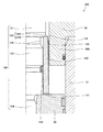
そこで、図2に示すように、油圧シリンダ100のピストンロッド30は、シリンダヘッド50の内周と摺接する本体部31と、本体部31より径が小さい小径部32と、本体部31と小径部32との間に中心軸に対して傾斜して形成される第1テーパ部33と、ピストンロッド30の先端に形成されピストン20が締結されるねじ部34と、を備える。
Therefore, as shown in FIG. 2, the
ピストンロッド30の第1テーパ部33は中心軸に対して傾斜して形成されるため、シリンダヘッド50をピストンロッド30に挿入する際に、シリンダヘッド50の内側に設けられるサブシール56、メインシール57、及びダストシール58といったシール部材がピストンロッド30に引っかかることが防止される。つまり、第1テーパ部33は、組み立て性確保のためのテーパ部として機能する。
Since the
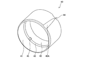
油圧シリンダ100のクッションベアリング40は、ピストンロッド30のストローク端付近でシリンダヘッド50のベアリング受容部50Aの内側に進入する進入部41と、ピストンロッド30の第1テーパ部33とピストン20との間に設けられる位置決め部42と、位置決め部42と進入部41の間であって中心軸に対して傾斜して内周に形成される当接部としての第2テーパ部43と、を備える。
The cushion bearing 40 of the
クッションベアリング40の外周には、中心軸に対して傾斜するテーパ溝40Aが形成される。テーパ溝40Aは、深さがクッションベアリング40のピストン20側から軸方向に沿って徐々に深くなるように形成される。このため、テーパ溝40Aは、クッションベアリング40がシリンダヘッド50のベアリング受容部50Aの内側に進入した際に、通過する作動油に抵抗を付与する可変絞りとして機能する。テーパ溝40Aの形状は、通過する作動油に付与する抵抗に合わせて任意に形成することができる。
A tapered
クッションベアリング40の進入部41の内径は、ピストンロッド30の本体部31の外径より大きく形成され、外径はシリンダヘッド50のベアリング受容部50Aの内径より小さく形成される。このように、クッションベアリング40の進入部41は、ピストンロッド30の本体部31の外周面と第1内周隙間6を持って設けられると共に、ピストンロッド30のストローク端付近においてシリンダヘッド50のベアリング受容部50Aの内側に進入するように設けられる。
The inner diameter of the
クッションベアリング40の位置決め部42の内径は、ピストンロッド30の小径部32の外径より大きく、ピストンロッド30の本体部31の外径より小さく形成される。このように、クッションベアリング40の位置決め部42は、ピストンロッド30の外周面との間に第2内周隙間7を持って設けられる。
The inner diameter of the
位置決め部42は、ピストンロッド30の第1テーパ部33とピストン20との間で軸方向にわずかに移動可能に形成される。クッションベアリング40が、ピストン20側に移動した際には、端面がピストン20と当接する。
The positioning
位置決め部42のピストン20側の端面には、径方向に延在する溝部44が設けられる。
A
クッションベアリング40の第2テーパ部43は、ピストンロッド30に対する傾斜角が、ピストンロッド30の第1テーパ部33と略同一となるように形成される。クッションベアリング40がピストン20とは反対側に移動した際には、第2テーパ部43がピストンロッド30の第1テーパ部33と当接する。つまり、ピストンロッド30の第1テーパ部33は、クッションベアリング40の軸方向の位置を決める座面として機能する。クッションベアリング40の第2テーパ部43は、ピストンロッド30の第1テーパ部33と当接可能であれば、その傾斜角は同一に形成しなくてもよく、直角な段差として形成してもよい。
The
このように、油圧シリンダ100によれば、ピストンロッド30の第1テーパ部33が、組み立て性確保のためのテーパ部とクッションベアリング40の座面との両方の機能を兼ねるため、ピストンロッド30の本体部31と先端側のねじ部34との外径差を少なくすることができる。
Thus, according to the
次に、図2及び図3を参照して、油圧シリンダ100のクッション動作について説明する。
Next, the cushioning operation of the
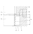
図2はピストンロッド30が伸長してストローク端付近にある状態を示し、図3はピストンロッド30がストローク端付近から収縮する状態を示している。
FIG. 2 shows a state where the
ボトム側室3に油圧ポンプが連通し、ロッド側室2にタンクが連通すると、ボトム側室3には作動油が供給され、ロッド側室2内の作動油はタンクに排出されるため、ピストンロッド30は伸長する。
When the hydraulic pump communicates with the bottom side chamber 3 and the tank communicates with the
ピストンロッド30が伸長すると、クッションベアリング40は、ロッド側室2から排出される作動油によってピストン20とは反対側にわずかに移動し、図2に示すように、ピストンロッド30の第1テーパ部33とクッションベアリング40の第2テーパ部43とが当接する。
When the
ピストンロッド30が伸長してストローク端に近づくと、クッションベアリング40は進入部41からシリンダヘッド50のベアリング受容部50Aの内側に進入し、クッションベアリング40の外周面とベアリング受容部50Aの内周面とによってクッション通路5が形成される。ピストンロッド30の第1テーパ部33とクッションベアリング40の第2テーパ部43が当接しているため、第1内周隙間6と第2内周隙間7との連通は遮断される。したがって、ロッド側室2の作動油は、クッションベアリング40の内側を通じては排出されず、クッション通路5を通じて排出される。クッション通路5によってロッド側室2内から排出される作動油には抵抗が付与されるため、ロッド側室2内の圧力低下が抑制されて、ピストンロッド30が減速する。このようにして、ピストンロッド30の伸長時におけるストローク端付近におけるクッション作用が発揮される。
When the
ロッド側室2に油圧ポンプが連通し、ボトム側室3にタンクが連通すると、ロッド側室2には作動油が供給され、ボトム側室3内の作動油はタンクに排出されるため、ピストンロッド30は収縮する。
When the hydraulic pump communicates with the
ピストンロッド30が最伸長状態から収縮する際には、図3に示すように、クッションベアリング40は、ロッド側室2に供給される作動油によってピストン20側に移動し、端面がピストン20に当接する。ピストンロッド30の第1テーパ部33とクッションベアリング40の第2テーパ部43とは離れるため、ポンプから供給される作動油は、クッション通路5を通じてロッド側室2へ導かれると共に、第1内周隙間6、第2内周隙間7、及びクッションベアリング40の溝部44を通じてロッド側室2へ導かれる。このため、ピストンロッド30が最伸長状態から収縮する場合には、ロッド側室2に作動油が速やかに流入し、収縮作動時の応答性が確保される。
When the
以上の実施形態によれば、以下に示す効果を奏する。 According to the above embodiment, there exist the effects shown below.
油圧シリンダ100では、ピストンロッド30の外周には中心軸に対して傾斜する第1テーパ部33が形成され、クッションベアリング40の内周には中心軸に対して傾斜する第2テーパ部43が形成される。クッションベアリング40は、第2テーパ部43がピストンロッド30の第1テーパ部33に当接することによってピストンロッド30に対して位置決めされる。このように、第1テーパ部33が、クッションベアリング40の座面と組み立て性確保のためのテーパ部との両方の機能を兼ねるため、ピストンロッド30の本体部31と先端側のねじ部34との外径差を少なくすることができる。したがって、ピストン20が締結されるねじ部34の径を大きくすることができ、ピストンロッド30の強度を向上させることができる。
In the
また、クッションベアリング40の座面としての鉛直部133B(図8参照)をピストンロッド30に設ける必要がないため、ピストンロッド30に応力集中を防止するための逃げ部を設ける必要がない。このため、ピストンロッド30の製造時における加工工程が減少して加工が容易となり、製造コストを低減することができる。
Moreover, since it is not necessary to provide the
次に、本実施形態に係る油圧シリンダ100の変形例を示す。
Next, a modification of the
上記実施形態では、ピストンロッド30の伸長時において、ピストンロッド30の第1テーパ部33とクッションベアリング40の第2テーパ部43とが当接することにより、クッションベアリング40の内側を通じた作動油の排出が遮断される構成であった。これに代えて、図4及び図5示すように、クッションベアリング40の第2テーパ部43に、第1内周隙間6と第2内周隙間7を連通し、通過する作動油に抵抗を付与する切欠き部45を形成してもよい。切欠き部45は、ピストンロッド30の第1テーパ部33に形成してもよいし、ピストンロッド30の第1テーパ部33とクッションベアリング40の第2テーパ部の両方に形成してもよい。
In the above embodiment, when the
クッションベアリング40の第2テーパ部43に切欠き部45が形成されることにより、ピストンロッド30の伸長時において、ロッド側室2の作動油は、クッション通路5を通じて排出されると共に、クッションベアリング40の溝部44、第2内周隙間7、切欠き部45及び第1内周隙間6を通じて排出される。
By forming the
切欠き部45を通過する作動油にも抵抗が付与されるため、クッションベアリング40の内側を通過する作動油によってもクッション作用が発揮される。したがって、切欠き部45の形状を任意に設定することで、油圧シリンダ100のクッション特性を調整することができる。例えば、切欠き部45は、図4に示すように軸方向に垂直な断面を角状に形成してもよいし、図5に示すように軸方向に垂直な断面を円弧状に湾曲する曲面に形成してもよい。また、クッションベアリング40の内側を通過する作動油に抵抗を付与するために設けられるクッションシール150(図8参照)を設けなくてよいため、部品点数を削減することができる。
Since resistance is also given to the hydraulic fluid that passes through the
以上、本発明の実施形態について説明したが、上記実施形態は本発明の適用例の一部を示したに過ぎず、本発明の技術的範囲を上記実施形態の具体的構成に限定する趣旨ではない。 The embodiment of the present invention has been described above. However, the above embodiment only shows a part of application examples of the present invention, and the technical scope of the present invention is limited to the specific configuration of the above embodiment. Absent.
上記実施形態では、作動流体として作動油を用いたが、この代わりに例えば水溶性代替液等を用いてもよい。 In the above embodiment, the working oil is used as the working fluid. However, for example, a water-soluble alternative liquid or the like may be used instead.
また、上記実施形態では、クッションベアリング40の第2テーパ部43は、図2に示すように、軸方向の中程に形成される。これに代えて、図6や図7に示すように、ピストンロッド30の第1テーパ部33側や軸方向のピストン20側に形成してもよい。
Moreover, in the said embodiment, the
また、上記実施形態では、クッションベアリング40は、ピストンロッド30の外周面と隙間を持って設けられ、軸方向にわずかに移動するようなフローティング支持される構成であった。これに代えて、クッションベアリング40は、ピストンロッド30に締め付けられて固定される構成でもよい。
Moreover, in the said embodiment, the cushion bearing 40 was provided with the clearance gap between the outer peripheral surface of the
また、上記実施形態では、ベアリング受容部50Aは、シリンダヘッド50に設けられる構成であった。これに代えて、ベアリング受容部50Aは、シリンダチューブ10の内周に設けられてもよい。また、ベアリング受容部50Aは、シリンダヘッド50及びシリンダチューブ10とは別体の独立した部材として設けてもよい。
Further, in the above embodiment, the
また、上記実施形態では、クッションベアリング40の外周にテーパ溝40Aが形成されるが、テーパ溝40Aを形成しなくてもよい。
Moreover, in the said embodiment, although the taper groove |
100 油圧シリンダ (流体圧シリンダ)
2 ロッド側室
3 ボトム側室
5 クッション通路
10 シリンダチューブ
20 ピストン
30 ピストンロッド
33 第1テーパ部
40 クッションベアリング
41 進入部
42 位置決め部
43 第2テーパ部(当接部)
50 シリンダヘッド
50A ベアリング受容部
100 Hydraulic cylinder (Hydraulic pressure cylinder)
2 Rod side chamber 3
50
Claims (3)
中心軸に対して傾斜する第1テーパ部が外周に形成されるピストンロッドと、
前記ピストンロッドが挿入されるシリンダチューブと、
前記ピストンロッドの外周に設けられる筒状のクッションベアリングと、
前記クッションベアリングの進入を許容するベアリング受容部と、
ストローク端付近で前記クッションベアリングが前記ベアリング受容部の内側に進入した際に、前記クッションベアリングと前記ベアリング受容部との間に形成され、通過する作動流体に抵抗を付与するクッション通路と、を備え、
前記クッションベアリングは、
内周に前記第1テーパ部と当接可能な当接部を有し、
前記当接部が前記第1テーパ部に当接することによって、前記ピストンロッドに対して位置決めされることを特徴とする流体圧シリンダ。 A hydraulic cylinder that decelerates by cushion pressure generated near the stroke end of the piston rod,
A piston rod formed on the outer periphery with a first tapered portion inclined with respect to the central axis;
A cylinder tube into which the piston rod is inserted;
A cylindrical cushion bearing provided on the outer periphery of the piston rod;
A bearing receiving portion that allows the cushion bearing to enter; and
A cushion passage that is formed between the cushion bearing and the bearing receiving portion when the cushion bearing enters the inside of the bearing receiving portion in the vicinity of a stroke end, and imparts resistance to the working fluid that passes therethrough. ,
The cushion bearing is
An abutting portion capable of abutting on the first taper portion on an inner periphery;
The fluid pressure cylinder, wherein the contact portion is positioned with respect to the piston rod by contacting the first taper portion.
前記第1テーパ部及び前記当接部の少なくとも一方には、前記隙間に開口する溝部が形成されることを特徴とする請求項1に記載の流体圧シリンダ。 The cushion bearing is provided with a gap between the outer periphery of the piston rod,
2. The fluid pressure cylinder according to claim 1, wherein at least one of the first tapered portion and the contact portion is formed with a groove portion that opens to the gap.
前記第1テーパ部と前記第2テーパ部は、前記ピストンロッドの中心軸に対して同一の傾斜角で形成されることを特徴とする請求項1又は2に記載の流体圧シリンダ。 The contact portion is a second taper portion that is inclined with respect to a central axis of the cushion bearing,
The fluid pressure cylinder according to claim 1 or 2, wherein the first taper portion and the second taper portion are formed at the same inclination angle with respect to a central axis of the piston rod.
Priority Applications (6)
| Application Number | Priority Date | Filing Date | Title |
|---|---|---|---|
| JP2013242981A JP6275459B2 (en) | 2013-11-25 | 2013-11-25 | Fluid pressure cylinder |
| KR1020167011451A KR20160089357A (en) | 2013-11-25 | 2014-11-12 | Fluid Pressure Cylinder |
| CN201480061339.0A CN105705801A (en) | 2013-11-25 | 2014-11-12 | Hydraulic cylinder |
| US15/034,080 US20160273559A1 (en) | 2013-11-25 | 2014-11-12 | Fluid pressure cylinder |
| PCT/JP2014/079951 WO2015076163A1 (en) | 2013-11-25 | 2014-11-12 | Hydraulic cylinder |
| EP14864780.3A EP3076029A4 (en) | 2013-11-25 | 2014-11-12 | Hydraulic cylinder |
Applications Claiming Priority (1)
| Application Number | Priority Date | Filing Date | Title |
|---|---|---|---|
| JP2013242981A JP6275459B2 (en) | 2013-11-25 | 2013-11-25 | Fluid pressure cylinder |
Publications (2)
| Publication Number | Publication Date |
|---|---|
| JP2015102164A true JP2015102164A (en) | 2015-06-04 |
| JP6275459B2 JP6275459B2 (en) | 2018-02-07 |
Family
ID=53179430
Family Applications (1)
| Application Number | Title | Priority Date | Filing Date |
|---|---|---|---|
| JP2013242981A Active JP6275459B2 (en) | 2013-11-25 | 2013-11-25 | Fluid pressure cylinder |
Country Status (6)
| Country | Link |
|---|---|
| US (1) | US20160273559A1 (en) |
| EP (1) | EP3076029A4 (en) |
| JP (1) | JP6275459B2 (en) |
| KR (1) | KR20160089357A (en) |
| CN (1) | CN105705801A (en) |
| WO (1) | WO2015076163A1 (en) |
Families Citing this family (5)
| Publication number | Priority date | Publication date | Assignee | Title |
|---|---|---|---|---|
| JP7323103B2 (en) * | 2020-07-22 | 2023-08-08 | Smc株式会社 | hydraulic cylinder |
| GB2599623B (en) * | 2020-08-12 | 2023-09-20 | Caterpillar Inc | Elastomer-mounted split ring |
| US11067104B1 (en) * | 2020-11-16 | 2021-07-20 | Caterpillar Inc. | Integrated cylinder piston and bearing as a hydraulic cushion |
| US11319972B1 (en) * | 2021-05-11 | 2022-05-03 | Caterpillar Inc. | Hydraulic cylinder snubbing retention arrangement |
| US20260035885A1 (en) * | 2022-08-18 | 2026-02-05 | Caterpillar Inc. | Hydraulic Actuator for Work Machine |
Citations (5)
| Publication number | Priority date | Publication date | Assignee | Title |
|---|---|---|---|---|
| JPS62124302U (en) * | 1986-01-31 | 1987-08-07 | ||
| CH677963A5 (en) * | 1989-01-23 | 1991-07-15 | Hydraulika Gmbh | Hydraulic or pneumatic operating cylinder - has cylinder piston and piston rod, brake cylinder and brake bushing with throttles |
| JPH04290605A (en) * | 1991-01-10 | 1992-10-15 | Koyo Seiki Kk | Hydraulic cylinder |
| JP2004225777A (en) * | 2003-01-22 | 2004-08-12 | Komatsu Ltd | Hydraulic cylinder cushion device |
| CN202132305U (en) * | 2011-07-29 | 2012-02-01 | 合肥长源液压股份有限公司 | High-pressure oil cylinder with buffering device in rod cavity |
Family Cites Families (6)
| Publication number | Priority date | Publication date | Assignee | Title |
|---|---|---|---|---|
| JPH11230117A (en) | 1998-02-18 | 1999-08-27 | Kayaba Ind Co Ltd | Fluid pressure cylinder |
| JP4851992B2 (en) * | 2007-05-22 | 2012-01-11 | カヤバ工業株式会社 | Cushion ring and fluid pressure cylinder |
| CN202718966U (en) * | 2012-08-15 | 2013-02-06 | 山东同力液压装备有限公司 | Hydraulic oil cylinder buffering sleeve |
| CN202746329U (en) * | 2012-08-22 | 2013-02-20 | 徐州徐工液压件有限公司 | Step type buffering sleeve for hydraulic cylinder |
| CN203146482U (en) * | 2013-02-20 | 2013-08-21 | 无锡西姆莱斯石油专用管制造有限公司 | Rod chamber side buffer structure of hydraulic cylinder |
| CN203201899U (en) * | 2013-04-02 | 2013-09-18 | 山河智能装备股份有限公司 | Buffering hydraulic cylinder |
-
2013
- 2013-11-25 JP JP2013242981A patent/JP6275459B2/en active Active
-
2014
- 2014-11-12 WO PCT/JP2014/079951 patent/WO2015076163A1/en not_active Ceased
- 2014-11-12 EP EP14864780.3A patent/EP3076029A4/en not_active Withdrawn
- 2014-11-12 KR KR1020167011451A patent/KR20160089357A/en not_active Withdrawn
- 2014-11-12 US US15/034,080 patent/US20160273559A1/en not_active Abandoned
- 2014-11-12 CN CN201480061339.0A patent/CN105705801A/en active Pending
Patent Citations (5)
| Publication number | Priority date | Publication date | Assignee | Title |
|---|---|---|---|---|
| JPS62124302U (en) * | 1986-01-31 | 1987-08-07 | ||
| CH677963A5 (en) * | 1989-01-23 | 1991-07-15 | Hydraulika Gmbh | Hydraulic or pneumatic operating cylinder - has cylinder piston and piston rod, brake cylinder and brake bushing with throttles |
| JPH04290605A (en) * | 1991-01-10 | 1992-10-15 | Koyo Seiki Kk | Hydraulic cylinder |
| JP2004225777A (en) * | 2003-01-22 | 2004-08-12 | Komatsu Ltd | Hydraulic cylinder cushion device |
| CN202132305U (en) * | 2011-07-29 | 2012-02-01 | 合肥长源液压股份有限公司 | High-pressure oil cylinder with buffering device in rod cavity |
Also Published As
| Publication number | Publication date |
|---|---|
| US20160273559A1 (en) | 2016-09-22 |
| EP3076029A1 (en) | 2016-10-05 |
| CN105705801A (en) | 2016-06-22 |
| WO2015076163A1 (en) | 2015-05-28 |
| EP3076029A4 (en) | 2017-08-09 |
| JP6275459B2 (en) | 2018-02-07 |
| KR20160089357A (en) | 2016-07-27 |
Similar Documents
| Publication | Publication Date | Title |
|---|---|---|
| JP6275459B2 (en) | Fluid pressure cylinder | |
| EP2775152B1 (en) | Hydraulic cylinder and method for manufacturing same | |
| US20180031012A1 (en) | Fluid pressure cylinder | |
| JP2017002808A5 (en) | ||
| JP5767991B2 (en) | Fluid pressure cylinder | |
| WO2014171178A1 (en) | Piston for axial piston pump motor, cylinder block for axial piston pump motor, and axial piston pump motor | |
| KR102625996B1 (en) | Vibration damper having a hydraulic end stop | |
| JP2015200379A (en) | Cushion device for hydraulic cylinder | |
| CN104685224A (en) | Hydraulic cylinder | |
| JP5767990B2 (en) | Fluid pressure cylinder | |
| JP6255440B2 (en) | Fluid pressure cylinder | |
| US10451093B2 (en) | Fluid pressure cylinder | |
| CN215634634U (en) | Buffer cylinder and working machinery | |
| JP4040480B2 (en) | Hydraulic cylinder cushion device | |
| JP7457605B2 (en) | Multi-stage fluid pressure cylinder | |
| JP6069125B2 (en) | Fluid pressure cylinder | |
| JP7431919B1 (en) | fluid pressure cylinder | |
| JP5730058B2 (en) | Fluid pressure cylinder | |
| JP2021076145A (en) | Cylinder device | |
| JP7842594B2 (en) | Fluid pressure cylinder | |
| JP7766066B2 (en) | Fluid Pressure Cylinder | |
| JP2016217382A (en) | Hydraulic cylinder | |
| JP2017002809A5 (en) | ||
| JP5647921B2 (en) | Cushion mechanism of fluid pressure cylinder | |
| JPH0514608U (en) | Hydraulic cylinder cushion device |
Legal Events
| Date | Code | Title | Description |
|---|---|---|---|
| A621 | Written request for application examination |
Free format text: JAPANESE INTERMEDIATE CODE: A621 Effective date: 20160721 |
|
| RD02 | Notification of acceptance of power of attorney |
Free format text: JAPANESE INTERMEDIATE CODE: A7422 Effective date: 20161216 |
|
| A131 | Notification of reasons for refusal |
Free format text: JAPANESE INTERMEDIATE CODE: A131 Effective date: 20170523 |
|
| A601 | Written request for extension of time |
Free format text: JAPANESE INTERMEDIATE CODE: A601 Effective date: 20170718 |
|
| A521 | Request for written amendment filed |
Free format text: JAPANESE INTERMEDIATE CODE: A523 Effective date: 20170906 |
|
| A131 | Notification of reasons for refusal |
Free format text: JAPANESE INTERMEDIATE CODE: A131 Effective date: 20171003 |
|
| A521 | Request for written amendment filed |
Free format text: JAPANESE INTERMEDIATE CODE: A523 Effective date: 20171129 |
|
| TRDD | Decision of grant or rejection written | ||
| A01 | Written decision to grant a patent or to grant a registration (utility model) |
Free format text: JAPANESE INTERMEDIATE CODE: A01 Effective date: 20171212 |
|
| A61 | First payment of annual fees (during grant procedure) |
Free format text: JAPANESE INTERMEDIATE CODE: A61 Effective date: 20180110 |
|
| R151 | Written notification of patent or utility model registration |
Ref document number: 6275459 Country of ref document: JP Free format text: JAPANESE INTERMEDIATE CODE: R151 |
|
| S533 | Written request for registration of change of name |
Free format text: JAPANESE INTERMEDIATE CODE: R313533 |
|
| R350 | Written notification of registration of transfer |
Free format text: JAPANESE INTERMEDIATE CODE: R350 |