JP2015102171A - Pipeline connection structure - Google Patents
Pipeline connection structure Download PDFInfo
- Publication number
- JP2015102171A JP2015102171A JP2013243213A JP2013243213A JP2015102171A JP 2015102171 A JP2015102171 A JP 2015102171A JP 2013243213 A JP2013243213 A JP 2013243213A JP 2013243213 A JP2013243213 A JP 2013243213A JP 2015102171 A JP2015102171 A JP 2015102171A
- Authority
- JP
- Japan
- Prior art keywords
- stopper
- cylindrical member
- peripheral surface
- connection structure
- outer peripheral
- Prior art date
- Legal status (The legal status is an assumption and is not a legal conclusion. Google has not performed a legal analysis and makes no representation as to the accuracy of the status listed.)
- Pending
Links
Images


Landscapes
- Quick-Acting Or Multi-Walled Pipe Joints (AREA)
Abstract
【課題】加水分解による劣化を抑制して、耐久性を向上させた配管接続構造を得る。
【解決手段】樹脂製の筒部材20には、筒部材20の外周面から径方向外側にストッパ部24が形成されている。ストッパ部24は、管体18の先端面が突き当てられるストッパ面24Aを有している。外周面とストッパ面44Aの間には、管体18の先端面の径方向内端部とを非当接にすると共に外気に連通する非当接空間28を構成する溝26が形成されている。
【選択図】図2A pipe connection structure with improved durability by suppressing degradation due to hydrolysis.
A stopper portion 24 is formed on a cylindrical member 20 made of resin from the outer peripheral surface of the cylindrical member 20 radially outward. The stopper portion 24 has a stopper surface 24A against which the distal end surface of the tubular body 18 is abutted. Between the outer peripheral surface and the stopper surface 44A, there is formed a groove 26 that constitutes a non-contacting space 28 that makes the radially inner end of the distal end surface of the tubular body 18 non-contacting and communicates with the outside air. .
[Selection] Figure 2
Description
本発明は、配管接続構造に係り、特に樹脂材を介して配管を接続する配管接続構造に関する。 The present invention relates to a pipe connection structure, and more particularly to a pipe connection structure for connecting pipes via a resin material.
近年、成型の容易性や軽量化の目的から、金属材に代えて樹脂材をホース等の管体との接続部材として用いることが行われている(例えば、特許文献1参照)。しかしながら、樹脂材は金属材に比べて劣化しやすく、特に加水分解による劣化を考慮した対応策が求められている。 In recent years, for the purpose of ease of molding and weight reduction, a resin material is used as a connection member for a tube body such as a hose instead of a metal material (see, for example, Patent Document 1). However, the resin material is easily deteriorated as compared with the metal material, and there is a demand for a countermeasure in consideration of deterioration due to hydrolysis.
本発明は、上記事実を考慮して成されたものであり、加水分解による劣化を考慮して、耐久性を向上させた配管接続構造を得ることが目的である。 The present invention has been made in view of the above facts, and an object thereof is to obtain a pipe connection structure with improved durability in consideration of degradation due to hydrolysis.
請求項1記載の発明に係る配管接続構造は、筒状とされ、筒内に流体の流路が形成された樹脂性の筒部材と、前記筒部材の外周面よりも径方向外側に配置され、前記筒部材に外挿された管体の先端面が突き当てられるストッパ面を有するストッパ部と、前記筒部材の外周面と前記ストッパ面との間に形成され、外挿された前記管体の先端面の径方向内端部と前記ストッパ部とを非当接にすると共に外気に連通する非当接空間を形成する離間部と、を備えている。 The pipe connection structure according to the first aspect of the present invention has a tubular shape, and is disposed on the outer side in the radial direction from the outer peripheral surface of the tubular member, and a resin tubular member having a fluid flow path formed in the tube. The tubular body formed between the outer peripheral surface of the tubular member and the stopper surface, and a stopper portion having a stopper surface against which the distal end surface of the tubular body externally attached to the tubular member is abutted And a separation portion that forms a non-contact space that communicates with the outside air while making the inner end portion in the radial direction of the distal end surface of the tip end surface non-contact with the stopper portion.
請求項1記載の配管接続構造では、管体は筒部材の外周に外挿され、ストッパ部のストッパ面に先端面が突き当てられて接続されている。そして、管体の先端面の径方向内端部とストッパ部とは、非当接空間が形成されていることで非当接とされている。したがって、管体に外力が作用した時に応力集中する筒部材の外周面とストッパ部との境界部分に、管体の先端面(管体の先端面の径方向内端部)が当接しない。また、非当接空間は外気に連通している。これにより、前記境界部分は、管体の内周面と筒状体の間を伝って入り込む水の影響を受け難くなり、加水分解による劣化を抑制することができる。 In the pipe connection structure according to the first aspect, the tubular body is extrapolated to the outer periphery of the cylindrical member, and the distal end surface is abutted against and connected to the stopper surface of the stopper portion. And the radial direction inner end part and stopper part of the front-end | tip surface of a tubular body are made into non-contact because the non-contact space is formed. Therefore, the distal end surface of the tubular body (the radially inner end portion of the distal end surface of the tubular body) does not contact the boundary portion between the outer peripheral surface of the cylindrical member and the stopper portion where stress concentrates when an external force is applied to the tubular body. The non-contact space communicates with the outside air. Thereby, the said boundary part becomes difficult to receive the influence of the water which penetrates between the internal peripheral surface of a tubular body, and a cylindrical body, and can suppress degradation by hydrolysis.
請求項2記載の発明に係る配管接続構造は、前記ストッパ部が、前記筒部材の外周に互いに離間して複数設けられている、ことを特徴とする。 The pipe connection structure according to a second aspect of the present invention is characterized in that a plurality of the stopper portions are provided apart from each other on the outer periphery of the cylindrical member.
請求項2記載の発明に係る配管接続構造によれば、複数のストッパ部が互いに離間して設けられているので、非当接空間を簡単に外気と連通させることができる。 According to the pipe connection structure according to the second aspect of the invention, since the plurality of stopper portions are provided apart from each other, the non-contact space can be easily communicated with the outside air.
請求項3記載の発明に係る配管接続構造は、前記ストッパ部は、前記筒部材の径方向外側へ突出する凸部として形成され、前記凹部は、前記ストッパ部の根元に前記筒部材の外周面に沿って形成された溝として構成されている、ことを特徴とする。 In the pipe connection structure according to a third aspect of the present invention, the stopper portion is formed as a convex portion protruding outward in the radial direction of the cylindrical member, and the concave portion is an outer peripheral surface of the cylindrical member at the root of the stopper portion. It is comprised as a groove | channel formed along.
請求項3記載の発明に係る配管接続構造によれば、筒部材の径方向外側へ突出する凸部を形成し、凸部の根元に筒部材の外周面に沿って溝を形成することにより、容易にストッパ部及び離間部を形成することができる。 According to the pipe connection structure according to the invention of claim 3, by forming the convex portion protruding radially outward of the cylindrical member, by forming a groove along the outer peripheral surface of the cylindrical member at the base of the convex portion, The stopper portion and the separation portion can be easily formed.
請求項4記載の発明に係る配管接続構造は、前記筒部材は配管対象部材の配管面から突出形成され、前記ストッパ部は前記配管面から突出形成されると共に前記筒部材の外周面と離間配置されている、ことを特徴とする。 According to a fourth aspect of the present invention, in the pipe connection structure, the cylindrical member is formed to protrude from the piping surface of the piping target member, and the stopper portion is formed to protrude from the piping surface and is spaced from the outer peripheral surface of the cylindrical member. It is characterized by being.
請求項4記載の発明に係る配管接続構造によれば、筒部材が配管対象部材の配管面から突出形成されている場合に、筒部材の外周面と離間配置するようにストッパ部を配管面から突出形成する。これにより、離間部が筒部材の外周面とストッパ部との間に形成され、容易にストッパ部及び離間部を形成することができる。 According to the pipe connection structure according to the fourth aspect of the present invention, when the cylindrical member is formed to protrude from the piping surface of the piping target member, the stopper portion is separated from the outer peripheral surface of the cylindrical member so as to be spaced apart from the outer peripheral surface of the cylindrical member. Protrusions are formed. Thereby, a separation | spacing part is formed between the outer peripheral surface of a cylinder member, and a stopper part, and a stopper part and a separation | spacing part can be formed easily.
請求項1に係る配管接続構造によれば、応力集中する筒部材の外周面とストッパ部との境界部分の加水分解による劣化を抑制して、耐久性を向上させることができる。 According to the pipe connection structure according to the first aspect, it is possible to improve the durability by suppressing degradation due to hydrolysis of the boundary portion between the outer peripheral surface of the cylindrical member where the stress is concentrated and the stopper portion.
請求項2に係る配管接続構造によれば、簡易な構成で非当接空間を外気と連通させることができる。 According to the pipe connection structure of the second aspect, the non-contact space can be communicated with the outside air with a simple configuration.
請求項3に係る配管接続構造によれば、ストッパ部及び離間部を簡易な構成にすることができる。 According to the pipe connection structure according to the third aspect, the stopper portion and the separation portion can be configured simply.
請求項4に係る配管接続構造によれば、ストッパ部及び離間部を簡易な構成にすることができる。 According to the pipe connection structure according to the fourth aspect, the stopper portion and the separation portion can be simplified.
[第1実施形態]
本発明の第1実施形態に係る配管接続構造について、図1及び図2を参照して説明する。本実施形態の配管接続構造10は、円筒状の筒部材20を備えている。筒部材20の筒軸方向を一点鎖線で示し符号Sを付している。筒部材20の筒内には、流体の流路Rが形成されている。筒部材20の一端20A側には、厚肉部22が形成されている。厚肉部22は、断面形状が三角形となるように、一端20Aから徐々に大径になるテーパー状と、厚肉部22の最大径の部分から徐々に小径になるテーパー状が連続で形成されている。筒部材20には、管体18が接続される。管体18は、一端20A側から筒部材20に外挿される。
[First embodiment]
A pipe connection structure according to a first embodiment of the present invention will be described with reference to FIGS. 1 and 2. The
筒部材20の筒軸方向Sの中間部には、筒部材20と一体的にストッパ部24が形成されている。ストッパ部24は、筒部材20の外周から径方向外側へ突出する凸部として形成され、筒部材20の筒部材20の周方向を長手方向として形成されている。ストッパ部24は、筒部材20の筒軸方向Sの中間部の同一円周上に互いに等間隔で離間して4カ所に形成されている。
A
図2(A)(B)に示されるように、ストッパ部24の一端20A側の径方向内側には、離間部としての溝26が形成されている。溝26は、断面が矩形状とされている。溝26により、接続された状態の管体18の先端面の径方向内端部18Aとストッパ部24とは非当接となっている。また、筒部材20の外周面20Bとストッパ面24Aとの間に非当接空間28が形成される。非当接空間28は、ストッパ部24の周方向両端で外気と連通されている。
As shown in FIGS. 2A and 2B, a
図2(B)に示されるように、管体18の先端面の径方向内端部18Aよりも径方向外側の外端部18Bは、ストッパ部24の一端20A側に形成されるストッパ面24Aに突き当てられる。ストッパ面24Aは、筒部材20の外周面20Bと略垂直に配置されている。ストッパ部24のストッパ面24Aと反対側の面は、筒部材20の外周と鈍角をなす傾斜面24Bとされている。
As shown in FIG. 2 (B), the
なお、ストッパ部24の筒部材20の外周面20Bからの突出長L1は、管体18の厚みWよりも長いことが好ましい。
The protruding length L1 of the
筒部材20の他端側(一端20Aと反対側)は、他の部材の流路(不図示)と接続可能な構成、例えば、テーパーネジや、フランジ等に形成することができる。筒部材20は、継手として利用することができる。
The other end side (the side opposite to the one
次に、本実施形態の作用効果について説明する。 Next, the function and effect of this embodiment will be described.
管体18を筒部材20と接続する際には、管体18を筒部材20の一端20A側から外挿し、管体18の外端部18Bをストッパ面24Aに突き当てる。そして、厚肉部22よりもストッパ部24側に締結バンド19を施して、管体18を筒部材20に固定する。
When connecting the
この状態で使用され、管体18及び筒部材20の流路Rには液体が流通する。長期の使用により、筒部材20の内周面20C(流路Rを構成する内壁)は、加水分解による劣化が進行すると考えられる。また、筒部材20の外周面20Bで管体18の内周面18Cと接触している部分についても、分子レベルで液体が浸入し、加水分解が進行すると考えられる。図2(B)には、加水分解による劣化が進行すると考えられる部分を網掛けで図示している。ここで、管体18に外力が加わり、筒部材20に径方向の力が作用すると、筒部材20の外周面20Bとストッパ部24との境界部分29に応力は集中する。本実施形態では、非当接空間28が形成されていることによって、境界部分29は管体18の内端部18A、内周面18Cと接触せず、加水分解による劣化の進行が抑制されている。したがって、管体18への外力作用による筒部材20の損傷が抑制され、配管接続構造10の耐久性を向上させることができる。
The liquid is used in this state and flows through the flow path R of the
なお、本実施形態では、ストッパ部24を筒部材20の外周に4個設けたが、ストッパ部の個数は1〜3個、及び5個以上でもよい。また、ストッパ部を複数設ける場合に、必ずしも互いに等間隔で離間させる必要はないが、等間隔で離間させることにより、バランスよく管体をストッパ面に突き当て、安定した接続を行うことができる。
In this embodiment, four
また、ストッパ部は、筒部材20の外周の全周に亘るように環状としてもよい。この場合には、溝26を外気と連通させるために、ストッパ部に溝26と連通する貫通孔を形成すればよい。
The stopper portion may be annular so as to extend over the entire outer periphery of the
また、本実施形態では、溝26の断面は矩形状としたが、他の形状、例えば、図3(A)に示すように半円状の溝26Aとしてもよいし、図3(B)に示すように三角形状の溝26Bとしてもよい。
In this embodiment, the
[第2実施形態]
次に、本発明に係る配管接続構造の第2実施形態について説明する。なお、本実施形態において、第1実施形態と同様の部分には同一の符号を付し、その詳細な説明を省略する。
[Second Embodiment]
Next, a second embodiment of the pipe connection structure according to the present invention will be described. In the present embodiment, the same parts as those in the first embodiment are denoted by the same reference numerals, and detailed description thereof is omitted.
図4及び図5に示すように、本実施形態の配管接続構造12は、筒部材30、配管対象壁32、及びストッパ部34を備えている。
As shown in FIGS. 4 and 5, the
配管対象壁32は、ラジエータなどの、外部からの配管が接続されて内部に流体が供給される器機の筐体や外壁の一部で構成されている。筒部材30は、円筒状とされ、配管対象壁32の壁面32Aから突出して形成されている。筒部材30の筒内には、流体の流路Rが形成されている。流路Rは、配管対象壁32の内側の配管(不図示)と連通されている。また、筒部材30の先端30A側には、厚肉部22が形成されている。
The piping
配管対象壁32には、筒部材30の基端側の径方向外側に、ストッパ部34が一体的に形成されている。ストッパ部34は、筒部材30の外周面30Bに沿って等間隔に4個形成されている。ストッパ部34は、配管対象壁32の壁面32Aから突出形成され、筒部材30の外周面30Bと離間配置され、壁面32A、ストッパ部34、及び外周面30Bの間に離間部36が形成されている。この離間部36により、接続された状態の管体18の内端部18Aとストッパ部34とは非当接となる。ストッパ部34の先端には、平坦状のストッパ面34Aが形成されている。離間部36には、非当接空間38が構成される。
A
図5(A)(B)に示されるように、ストッパ面34Aは、筒部材30の外周面30Bと略垂直に配置されている。管体18の外端部18Bは、ストッパ面34Aに突き当てられる。非当接空間38は、ストッパ部34の周方向両端で外気と連通されている。
As shown in FIGS. 5A and 5B, the
なお、筒部材30、配管対象壁32、及びストッパ部34は、樹脂製とされ、樹脂としては、ナイロン(PA)、ポリプロピレン(PP)等を用いることができる。また、ストッパ部34の筒部材30の外周面30Bからの突出長L2は、管体18の厚みWよりも長いことが好ましい。
The
次に、本実施形態の作用効果について説明する。 Next, the function and effect of this embodiment will be described.
管体18を筒部材30と接続する際には、管体18を筒部材30の先端30A側から外挿し、図5(B)に示されるように、管体18の外端部18Bをストッパ面34Aに突き当てる。そして、厚肉部22よりもストッパ部34側に締結バンド19を施して、管体18を筒部材30に固定する。
When connecting the
本実施形態でも、長期にわたって使用されると、筒部材30及び配管対象壁32の経年劣化が進行し、特に、筒部材30の内周面30C、及び、管体18の内周面18Cと接触する外周面30Bについて加水分解が進行すると考えられる。図5(B)には、加水分解による劣化が進行すると考えられる部分を網掛けで図示している。管体18に外力が加わり、筒部材30に径方向の力が作用する際に応力集中するのは、筒部材30の外周面と配管対象壁32との境界部分39である。本実施形態では、境界部分39は、管体18の内端部18A及び内周面18Cと接触せず、加水分解による劣化の進行が抑制されている。したがって、管体18への外力作用による筒部材30の損傷が抑制され、耐久性を向上させることができる。
Also in this embodiment, when used over a long period of time, the aging deterioration of the
なお、本実施形態でも、ストッパ部34を4個設けたが、ストッパ部の個数は1〜3個、及び5個以上でもよい。また、ストッパ部は、筒部材30の外周の全周に亘るように環状としてもよい。ストッパ部を、筒部材30の外周の全周に亘る環状とする場合には、径方向に貫通孔を形成して非当接空間38を外気と連通させる。
In the present embodiment, four
[第3実施形態]
次に、本発明に係る配管接続構造の第3実施形態について説明する。なお、本実施形態において、第1、第2実施形態と同様の部分には同一の符号を付し、その詳細な説明を省略する。
[Third embodiment]
Next, a third embodiment of the pipe connection structure according to the present invention will be described. In the present embodiment, the same parts as those in the first and second embodiments are denoted by the same reference numerals, and detailed description thereof is omitted.
図6、に示すように、本実施形態の配管接続構造14は、筒部材40及び大径接続部42を備えている。筒部材40は、第2実施形態の筒部材30と同一形状とされ、一端40A側に厚肉部22が形成されている。筒部材40の筒軸方向Sの厚肉部22と反対側には、筒部材40と一体的に大径接続部42が形成されている。大径接続部42は、筒部材40よりも大径の円筒状とされ、筒内に流路Rと連通する流路R1が形成されている。
As shown in FIG. 6, the
筒部材40と大径接続部42の間には、環状の段差壁面42Aが形成されている。段差壁面42Aは、筒部材40の外周面40Bと略垂直に配置されている。段差壁面42Aには、ストッパ部44が形成されている。ストッパ部44は、筒部材40の外周に沿って等間隔に4個形成されている。
Between the
ストッパ部44は、段差壁面42Aから一端40A側に突出形成されている。ストッパ部44の径方向外側面は、大径接続部42の外周面42Bと面一とされている。ストッパ部44は、筒部材40の外周面40Bと離間配置され、段差壁面42A、ストッパ部44、及び外周面40Bの間に離間部46が形成されている。この離間部46により、接続された状態の管体18の内端部18Aとストッパ部44とは非当接となる。ストッパ部44の先端には、平坦状のストッパ面44Aが形成されている。離間部46には、非当接空間48が構成される。
The
図7(A)(B)に示されるように、ストッパ面44Aは、筒部材40の外周と略垂直に配置されている。 図7(B)に示されるように、管体18の外端部18Bは、ストッパ面44Aに突き当てられる。非当接空間48は、ストッパ部44の周方向両端で外気と連通されている。
As shown in FIGS. 7A and 7B, the
なお、筒部材40、大径接続部42、及びストッパ部44は、樹脂製とされ、樹脂としては、ナイロン(PA)、ポリプロピレン(PP)等を用いることができる。また、ストッパ部44の筒部材40の外周面40Bからの突出長L3は、管体18の厚みSよりも長いことが好ましい。
The
次に、本実施形態の作用効果について説明する。 Next, the function and effect of this embodiment will be described.
管体18を筒部材40と接続する際には、管体18を筒部材40の一端40A側から外挿し、管体18の外端部18Bをストッパ面44Aに突き当てる。そして、厚肉部22よりもストッパ部44側に締結バンド19を施して、管体18を筒部材40に固定する。
When connecting the
本実施形態でも、長期にわたって使用されると、筒部材40の経年劣化が進行し、特に、筒部材40の内周面40C、大径接続部42の内周面42C、及び、筒部材40の外周面40Bで管体18の内周面18Cと接触している部分の加水分解が進行すると考えられる。図7(B)には、加水分解による劣化が進行すると考えられる部分を網掛けで図示している。管体18に外力が加わり、筒部材40に径方向の力が作用する際に応力集中するのは、筒部材40の外周面と大径接続部42との境界部分49である。本実施形態では、境界部分49は、管体18の内端部18A、内周面18Cと接触せず、加水分解による劣化の進行が抑制されている。したがって、管体18への外力作用による筒部材40の損傷が抑制され、耐久性を向上させることができる。
Also in this embodiment, when used over a long period of time, the aging of the
なお、本実施形態では、ストッパ部44を4個設けたが、ストッパ部の個数は1〜3個、及び5個以上でもよい。また、ストッパ部は、筒部材40の外周の全周に亘るように環状としてもよい。ストッパ部を、筒部材40の外周の全周に亘る環状とする場合には、径方向に貫通孔を形成して非当接空間48を外気と連通させる。
また、非当接空間48の通気を確保するために、非当接空間48に対応する段差壁面42Aに筒軸S方向に貫通する孔を形成してもよい。なお、当該孔は、第1、第2実施形態の非当接空間に同様に形成してもよい。
In the present embodiment, four
Further, in order to ensure ventilation of the
以上の第1〜第3実施形態に係る配管接続構造は、自動車のエンジンルーム内の配管接続に用いることができる。特に、ラジエータなどの熱交換器の出入口や、冷却水用のエンジンのインレット/アウトレットに好適に用いることができる。 The pipe connection structure according to the first to third embodiments described above can be used for pipe connection in an engine room of an automobile. In particular, it can be suitably used for an inlet / outlet of a heat exchanger such as a radiator or an inlet / outlet of an engine for cooling water.
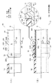
本発明の実施例として第3実施形態の配管接続構造14を用い、比較例として図8に示す配管接続構造Cを用いる。実施例及び比較例の筒部材に管体を接続し、管体に所定の外力を加え、筒部材の特定位置における応力測定を行った。
The
図8に示されるように、配管接続構造Cは、ストッパ部44を有していない点が配管接続構造14と異なっている。配管接続構造Cでは、ストッパ部44に代えて大径接続部42の段差壁面42Aに管体18の先端18Aが突き当てられる。また、配管接続構造Cでは、段差壁面42Aが、筒軸方向Sでストッパ面44Aに対応する位置に配置されている。
As shown in FIG. 8, the pipe connection structure C is different from the
応力の測定は、配管接続構造14では、境界部分49と、外周面20Bの筒軸方向Sでストッパ面44Aに対応する位置47とで測定し(図7(B)参照)、比較例の配管接続構造Cでは、外周面40Bと段差壁面42Aの境界部分43で測定した。比較例の境界部分43の応力をA、実施例の境界部分49の応力をB、位置47の応力をCとすると、応力の大きさは、B>A>C、となる。
In the
図9には、樹脂(ナイロン)について、時間(経時)と許容応力との関係を示すグラフが示されている。破線Iは樹脂(ナイロン)の熱による経時劣化を示し(以下、破線Iを「熱劣化ラインI」という)、実線IIは熱に加えて加水分解(配管内の液体に起因するもの)も含む経時劣化(以下、実線IIを「熱+加水分解劣化ラインII」という)を示している。実施例の位置47及び比較例の境界部分43については、管体18の内端部18Aと接触しているため、樹脂寿命は、熱+加水分解の劣化ラインIIから得られる。一方、実施例の境界部分49については、管体18の内端部18Aとの非接触であるため、樹脂寿命は、熱劣化ラインIから得られる。
FIG. 9 shows a graph showing the relationship between time (aging) and allowable stress for resin (nylon). The broken line I indicates deterioration of the resin (nylon) with heat (hereinafter, the broken line I is referred to as “thermal deterioration line I”), and the solid line II includes hydrolysis (due to liquid in the piping) in addition to heat. Deterioration with time (hereinafter, solid line II is referred to as “heat + hydrolysis deterioration line II”). Since the
測定によって得られた応力A、B、Cを、図9のグラフに当てはめて樹脂寿命を考察する。実施例の位置47における樹脂寿命(熱+加水分解の劣化ラインIIで許容応力がCになるまでの劣化時間CT)は、比較例の境界部分43における樹脂寿命(熱+加水分解の劣化ラインIIで許容応力がAになるまでの劣化時間AT)の約3.5倍になる。実施例の位置47では、外力が加わった時の応力が小さいので、許容応力も小さくてよいからである。なお、実施例の境界部分49に関して、熱劣化ラインIはBまで低下しておらず、劣化時間は位置47よりも長いと考えられる。したがって、実施例と比較例において、樹脂寿命は、位置47と境界部分43における樹脂寿命で比較することができる。前述のように、実施例の樹脂寿命は、比較例の3.5倍となり、実施例の耐久性が優れていることが確認できた。
The resin life is considered by applying the stresses A, B, and C obtained by the measurement to the graph of FIG. The resin life (deterioration time CT until the allowable stress becomes C in the heat + hydrolysis degradation line II) at the
10、12、14 配管接続構造
18 管体
18A 径方向内端部
20B 外周面
20 筒部材
24 ストッパ部
24A ストッパ面
26 溝(離間部)
28 非当接空間
30B 外周面
30 筒部材
32 配管対象壁(配管対象部材)
32A 壁面(配管面)
34 ストッパ部
34A ストッパ面
36 離間部
38 非当接空間
40B 外周面
40 筒部材
44 ストッパ部
44A ストッパ面
46 離間部
48 非当接空間
R 流路
10, 12, 14
28
32A Wall surface (pipe surface)
34
Claims (4)
前記筒部材の外周面よりも径方向外側に配置され、前記筒部材に外挿された管体の先端面が突き当てられるストッパ面を有するストッパ部と、
前記筒部材の外周面と前記ストッパ面との間に形成され、外挿された前記管体の先端面の径方向内端部と前記ストッパ部とを非当接にすると共に外気に連通する非当接空間を形成する離間部と、
を備えた配管接続構造。 A cylindrical member made of resin in which a fluid flow path is formed in the cylinder; and
A stopper portion having a stopper surface that is disposed radially outward from the outer peripheral surface of the cylindrical member and against which a distal end surface of a tubular body that is extrapolated to the cylindrical member is abutted;
A non-contact portion formed between the outer peripheral surface of the tubular member and the stopper surface and configured to make the radially inner end portion of the distal end surface of the tubular body extrapolated and the stopper portion non-contact and communicate with the outside air. A separation portion forming a contact space;
Piping connection structure with
前記離間部は、前記ストッパ部の根元に前記筒部材の外周面に沿って形成された溝として構成されている、ことを特徴とする請求項1または請求項2に記載の配管接続構造。 The stopper portion is formed as a convex portion protruding outward in the radial direction of the cylindrical member,
3. The pipe connection structure according to claim 1, wherein the separation portion is configured as a groove formed along an outer peripheral surface of the cylindrical member at a base of the stopper portion.
Priority Applications (1)
| Application Number | Priority Date | Filing Date | Title |
|---|---|---|---|
| JP2013243213A JP2015102171A (en) | 2013-11-25 | 2013-11-25 | Pipeline connection structure |
Applications Claiming Priority (1)
| Application Number | Priority Date | Filing Date | Title |
|---|---|---|---|
| JP2013243213A JP2015102171A (en) | 2013-11-25 | 2013-11-25 | Pipeline connection structure |
Publications (1)
| Publication Number | Publication Date |
|---|---|
| JP2015102171A true JP2015102171A (en) | 2015-06-04 |
Family
ID=53378035
Family Applications (1)
| Application Number | Title | Priority Date | Filing Date |
|---|---|---|---|
| JP2013243213A Pending JP2015102171A (en) | 2013-11-25 | 2013-11-25 | Pipeline connection structure |
Country Status (1)
| Country | Link |
|---|---|
| JP (1) | JP2015102171A (en) |
-
2013
- 2013-11-25 JP JP2013243213A patent/JP2015102171A/en active Pending
Similar Documents
| Publication | Publication Date | Title |
|---|---|---|
| EP3728925B1 (en) | Dual containment fitting assembly | |
| RU2009139634A (en) | DISTRIBUTED VALVE WITH IMPROVED DISTRIBUTION | |
| RU2589974C1 (en) | Fitting, system containing such fitting, and airtight connection with such fitting | |
| BRPI0408940B1 (en) | end fitting for a hose, tube assembly and tube assembly mounting method | |
| US9771708B2 (en) | Device for a hose fitting | |
| JP5738659B2 (en) | Inner cylinder member and joining structure of cylinder members | |
| RU2016138037A (en) | TUBE CONNECTION | |
| ES2399948T3 (en) | Connection of connection, in particular for the connection of solar collectors | |
| MX2023008997A (en) | Collecting tube assembly and heat exchanger. | |
| ES2400078T3 (en) | Corrugated pipe coupling | |
| JP2015102171A (en) | Pipeline connection structure | |
| US9581065B2 (en) | Welding structure of warm-up catalytic converter | |
| JP2019035364A5 (en) | ||
| JP6200723B2 (en) | Telescopic flexible tube and method for assembling telescopic flexible tube | |
| JP6043580B2 (en) | Pipe fitting | |
| KR20170065989A (en) | connection assembly of hose | |
| KR101734719B1 (en) | Air hose using different materials for vehicle | |
| JP6085048B2 (en) | nipple | |
| JP6642853B2 (en) | Pipe connection structure | |
| JP6389063B2 (en) | Sensor fixture | |
| JP6491715B2 (en) | Telescopic flexible tube and method for assembling telescopic flexible tube | |
| CN108332457A (en) | Shock absorbing pipe and air conditioner with it | |
| CN104075061A (en) | Negative-pressure resistant and corrosion resistant steel-lined Teflon expansion joint | |
| MX2022007906A (en) | Fuel piping, fuel piping connecting structure, and method for manufacturing fuel piping. | |
| JP5550947B2 (en) | Pipe fitting |