JP2015102710A - Stereoscopic display forming body - Google Patents
Stereoscopic display forming body Download PDFInfo
- Publication number
- JP2015102710A JP2015102710A JP2013243607A JP2013243607A JP2015102710A JP 2015102710 A JP2015102710 A JP 2015102710A JP 2013243607 A JP2013243607 A JP 2013243607A JP 2013243607 A JP2013243607 A JP 2013243607A JP 2015102710 A JP2015102710 A JP 2015102710A
- Authority
- JP
- Japan
- Prior art keywords
- image
- line
- information
- visually recognized
- color layer
- Prior art date
- Legal status (The legal status is an assumption and is not a legal conclusion. Google has not performed a legal analysis and makes no representation as to the accuracy of the status listed.)
- Granted
Links
Images












Landscapes
- Printing Methods (AREA)
- Credit Cards Or The Like (AREA)
Abstract
【課題】 本発明は、簡易な製造が可能であり、虚像の存在が容易に推考できず、かつ、光学的なシートを有さずに立体かつ動的な効果を奏する立体表示形成体を提供するものである。【解決手段】本発明は、第一の画像を光輝性を有する凹状の第一の情報画線を万線状に基材上に複数配列することによって、基材に対して所定の角度から観察した場合に、色彩を有する第一の画像が立体的に視認され、透過光においては、有色の模様として視認可能な立体表示形成体である。【選択図】 図1PROBLEM TO BE SOLVED: To provide a three-dimensional display forming body that can be easily manufactured, cannot easily infer the existence of a virtual image, and has a three-dimensional and dynamic effect without an optical sheet. To do. According to the present invention, the first image is observed from a predetermined angle with respect to the base material by arranging a plurality of concave first information lines having a glittering property on the base material. In this case, the first image having the color is visually recognized in three dimensions, and in the transmitted light, the three-dimensional display formation body is visible as a colored pattern. [Selection] Figure 1
Description
本発明は、光が入射することで、両眼視差を用いた立体画像が出現し、加えて光の入射角度の変化に応じて立体画像が動的に視認され、透過光では着色された画像が出現する形成体に関する。 In the present invention, when light enters, a stereoscopic image using binocular parallax appears, and in addition, a stereoscopic image is dynamically visually recognized according to a change in the incident angle of light, and an image colored with transmitted light. Relates to the formed body.
近年のスキャナ、プリンタ、カラーコピー機等のデジタル機器の進展により、貴重印刷物の精巧な複製物を容易に作製することが可能となっている。そのような複製や偽造を防止するために、偽造防止技術が必要とされている。そのような技術の一例として、観察角度により動的な画像が発現する立体表示形成体、あるいは観察角度により特定の色彩による情報が発現する記録媒体がある。 With recent developments in digital devices such as scanners, printers, and color copiers, it has become possible to easily produce elaborate copies of precious printed matter. In order to prevent such duplication and forgery, anti-counterfeiting technology is required. As an example of such a technique, there is a three-dimensional display forming body in which a dynamic image appears depending on an observation angle, or a recording medium in which information based on a specific color appears depending on the observation angle.
その一例として、回折格子上に、文字、画像等を輪郭で区分けして表示した後、その輪郭の内側又は外側を滑らかな曲線群からなる回折格子により形成し、視点を変化させて観察した場合に、輪郭の内側又は外側で回折格子により輝いて見える位置が滑らかに変化して視認されることを特徴とする表示体が開示されている(例えば、特許文献1参照)。 As an example of this, when characters, images, etc. are displayed on a diffraction grating with an outline, and then the inside or outside of the outline is formed by a diffraction grating consisting of a smooth curve group and the viewpoint is changed. In addition, there is disclosed a display body characterized in that a position that appears bright by a diffraction grating on the inner side or the outer side of a contour is visually recognized by changing smoothly (see, for example, Patent Document 1).
また、回折格子において、複数の微細線で形成された基本形状と、基本形状と同一形状の画像を合わせて一つの模様を形成し、一つの点を中心として回転方向に断続的に複数形成することで、立体的な模様が回転しているように視認される立体表示形成体が開示されている(例えば、特許文献2参照)。 Also, in the diffraction grating, a basic pattern formed by a plurality of fine lines and an image having the same shape as the basic shape are combined to form a single pattern, and a plurality of patterns are intermittently formed around the single point in the rotation direction. Thus, a three-dimensional display formed body that is visually recognized as if a three-dimensional pattern is rotating is disclosed (for example, see Patent Document 2).
また、観察角度により特定の色彩による情報が発現する記録媒体としては、互いに異なる色からなる複数の層を順次積層し、付与する情報に基づいて形成角度及び深度を有する複数の穴を形成した記録媒体であり、穴の観察方向により底面の層の見える色の違いによって特定の情報が発現する記録媒体が開示されている(例えば、特許文献3参照)。 In addition, as a recording medium that expresses information by a specific color depending on the observation angle, a recording layer in which a plurality of layers having different colors are sequentially stacked and a plurality of holes having a forming angle and a depth are formed based on the information to be provided. There is disclosed a recording medium that is a medium and expresses specific information depending on the difference in the color of the bottom layer depending on the observation direction of the hole (see, for example, Patent Document 3).
しかしながら、特許文献1の技術は、文字、画像等内を滑らかな曲線で形成して輝度による変化を視認する回折格子であり、文字、図形等の輝いて見える位置が、単に左右に移動するだけであり、文字や図形そのものが動的に視認することはできず、更には色彩による変化を奏することは困難であった。
However, the technique of
また、特許文献2の技術は、ステレオグラムの原理により立体視させているため、必ず同一の模様が二つ並んで形成される必要があり、動的に視認させるための複数の模様は、断続的に形成されている。よって、動的に視認される際、立体視される画像も断続的に視認されることから、連続的に動いて視認することはできず、更には色彩による変化を奏することは困難であった。
In addition, since the technique of
また、特許文献3の技術は、穴による色の違いによる情報を付与したものであり、画像に動的な変化はなく、模様を構成することは困難であった。
Further, the technique of
本発明は、前述した課題の解決を目的とするものであり、観察方向において立体、かつ、連続的に動的な視認効果を奏する色彩模様が表出し、透過光下においては、反射光下と異なる色の色彩模様が表出する立体表示形成体を提供するものである。 The present invention is intended to solve the above-described problems, and a three-dimensional and continuous color pattern showing a dynamic visual effect appears in the observation direction, and under transmitted light, under reflected light. It is an object of the present invention to provide a three-dimensional display forming body in which color patterns of different colors appear.
本発明は、明暗フリップフロップ性を有する透明基体の一方の面に積層した所定の透過率を有する第一の色彩層と、第一の色彩層と異なる色彩、かつ、所定の透過率と同一又は異なる透過率を有する第二の色彩層を他方の面に積層された基材と、第一の色彩層又は第二の色彩層の少なくとも一部に立体視可能な第一の画像が形成され、第一の画像は、第一の画像を構成する少なくとも一つの第一の要素領域から成り、第一の要素領域は、万線状に配置された、始点、頂点及び終点を有する円弧状の第一の情報画線から成り、円弧状の第一の情報画線は、第一の画像を形成する色彩層を完全に除去及び透明基体の一部を除去して成る凹形状、かつ、明暗フリップフロップ性を有する画線であり、基材を、定位置の光源に対して所定の角度から異なる角度へと、連続的に変化させて観察した場合、光源からの入射光を反射する位置が、円弧状の第一の情報画線上で徐々に移動することで、右目で視認される第一の画像と、左目で視認される第一の画像の位相が異なることで、両眼視差により第一の情報画線が形成された色彩層の色彩から成る第一の画像が立体的、かつ、動的に視認され、透過光下においては、第一の情報画線が形成された色彩層と異なる色彩層の色彩から成る第一の画像が視認されることを特徴とする立体表示形成体である。 The present invention provides a first color layer having a predetermined transmittance laminated on one surface of a transparent substrate having light and dark flip-flop properties, a color different from the first color layer, and the same or a predetermined transmittance. A base material in which a second color layer having different transmittance is laminated on the other surface, and a first image that can be stereoscopically viewed is formed on at least a part of the first color layer or the second color layer, The first image is composed of at least one first element region constituting the first image, and the first element region is a circular arc-shaped first element having a start point, a vertex, and an end point arranged in a line. An arc-shaped first information line consisting of one information line is a concave-shaped light-and-flip flip-flop formed by completely removing the color layer forming the first image and removing a part of the transparent substrate. This is an image line that has the property of being a The position where the incident light from the light source is reflected gradually moves on the arc-shaped first information line so that the first eye can be visually recognized by the right eye. The first image composed of the colors of the color layer in which the first information image line is formed by binocular parallax is different, and the first image visually recognized by the left eye is stereoscopic, A stereoscopic display forming body characterized in that a first image composed of colors of a color layer different from the color layer on which the first information image line is formed is visually recognized under transmitted light. is there.
また、本発明は、第一の画像と近接又は隣接する位置に立体視可能な第二の画像が形成され、第二の画像は、第二の画像を構成する少なくとも一つの第二の要素領域から成り、第二の要素領域は、第一の情報画線と同じ方向に万線状に配置された、始点、頂点及び終点を有する円弧状の第二の情報画線から成り、円弧状の第二の情報画線は、第二の情報画像を形成する色彩層及び透明基体の一部を除去して成る凹形状、かつ、明暗フリップフロップ性を有する画線であり、第一の画像を形成する第一の情報画線と頂点の向きが異なる方向に配置され、基材を、所定の角度から光源に対して異なる角度へと、連続的に変化させて観察した場合、第一の情報画線と第二の情報画線の頂点の向きが異なることで、右目で視認される第一の画像及び第二の画像と、左目で視認される第一の画像及び第二の画像の位相が異なることで、両眼視差により各情報画線が形成された色彩層の色彩から成る第一の画像及び第二の画像が立体的、かつ、異なる方向に動的に視認され、透過光下においては、第一の情報画線及び第二の情報画線が形成された色彩層と異なる色彩層の色彩から成る第一の画像及び第二の画像が視認されることを特徴とする立体表示形成体である。 According to the present invention, a second image that can be stereoscopically viewed is formed at a position close to or adjacent to the first image, and the second image is at least one second element region constituting the second image. The second element region is composed of an arc-shaped second information image line having a start point, a vertex, and an end point arranged in a line in the same direction as the first information image line. The second information image line is a concave shape formed by removing a part of the color layer and the transparent substrate forming the second information image, and has a light and dark flip-flop property. When the first information line to be formed and the direction of the apex are arranged in different directions, and the base material is observed while continuously changing from a predetermined angle to a different angle with respect to the light source, the first information Because the orientation of the vertex of the image line and the second information line is different, the first image and the second image visually recognized by the right eye The first image and the second image composed of the colors of the color layers in which the information lines are formed by binocular parallax because the first image and the second image visually recognized by the left eye are different in phase. 3D images are dynamically viewed in three directions and in different directions. Under transmitted light, the first information image line and the second information image line are composed of colors that are different from the color layer formed. A stereoscopic display forming body characterized in that a first image and a second image are visually recognized.
また、本発明は、第一の色彩層と第二の色彩層の色の差異は、色差が10以上であることを特徴とする立体表示形成体である。 Moreover, this invention is a three-dimensional display formation body characterized by the color difference of the color difference of a 1st color layer and a 2nd color layer being 10 or more.
本発明に係る立体表示形成体は、光輝性を有する材料から成る画線を、万線状に配列することによって、観察方向において立体、かつ、連続的に動的な視認効果を奏し、透過光下においては、有色の模様を視認することができる。 The three-dimensional display forming body according to the present invention has a three-dimensional and continuous dynamic visual effect in the observation direction by arranging image lines made of a material having a glitter property in a line shape, and transmits transmitted light. Below, a colored pattern can be seen.
さらに、色彩模様が表出する立体画像を形成する複数の画線を、同一方向に限らず異なる方向に配置することで、入射光に対する反射光が、複数の画線内において変化する。よって、異なる方向に配置した場合、立体画像の動的効果は、一つの画像内において一方向に限定されず、他方向に動的効果を奏して視認可能となり、従来と比べ、より複雑な動的効果を奏する画像として視認することが可能となる。 Furthermore, by arranging a plurality of image lines forming a stereoscopic image in which a color pattern appears in different directions as well as the same direction, the reflected light with respect to the incident light changes in the plurality of image lines. Therefore, when arranged in different directions, the dynamic effect of the stereoscopic image is not limited to one direction in one image, but can be visually recognized with a dynamic effect in the other direction. It can be visually recognized as an image having a special effect.
(第一の実施形態)
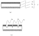
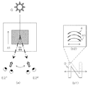
図1(a)は、本発明における立体表示形成体(1)(以下、「形成体」という。)が有する立体視可能な画像を示す平面図である。形成体(1)は、第一の画像(3)を有する。第一の画像(3)は、基材(2)に対して所定の角度から観察した場合に、色彩を有する画像が立体的に視認され、透過光においては、有色の模様として視認可能な画像である。第一の画像(3)は、光輝性を有する凹状の第一の情報画線(4)を万線状に複数配列して成る。図1(b)は、形成体(1)のA−A’断面図である。第一の画像(3)を形成する基材(2)は、中間層である透明基体(2a)の一方の面に形成された第一の色彩層(2b)と、他方の面に形成された第二の色彩層(2c)から成る。また、第一の情報画線(4)の凹状の深度は、各色彩層(2b、2c)以上の深度である。なお、第一の情報画線(4)は、一つの色彩層に二以上形成してもよく、各色彩層にそれぞれ重ならない位置に形成してもよい。
(First embodiment)
FIG. 1A is a plan view showing a stereoscopically visible image of the stereoscopic display formed body (1) (hereinafter referred to as “formed body”) in the present invention. The formed body (1) has a first image (3). When the first image (3) is observed from a predetermined angle with respect to the base material (2), an image having a color is viewed three-dimensionally, and an image that is visible as a colored pattern in transmitted light It is. The first image (3) is formed by arranging a plurality of concave first information lines (4) having a brilliant line shape. FIG.1 (b) is AA 'sectional drawing of a formation (1). The substrate (2) for forming the first image (3) is formed on the first color layer (2b) formed on one surface of the transparent substrate (2a) as an intermediate layer and on the other surface. And a second color layer (2c). Further, the concave depth of the first information image line (4) is a depth greater than each color layer (2b, 2c). Two or more first information image lines (4) may be formed in one color layer, or may be formed in positions that do not overlap each color layer.
基材(2)を形成する透明基体(2a)は、光輝性を有する材料により形成される。本発明における光輝性とは、明暗フリップフロップ性のことであり、観察角度の変化により明度の変化が生じることである。透明基体(2a)は、明暗フリップフロップ性を有する透明樹脂材料であるフィルム、プラスチック等があるが、明暗フリップフロップ性を有していれば特段限定されることはない。後述する第一の情報画線(4)が、透明基体(2a)を凹状に変形して形成するため、明暗フリップフロップ性を有していれば、第一の情報画線(4)が光輝性を有することとなる。 The transparent substrate (2a) forming the substrate (2) is formed of a material having glitter. The glitter in the present invention refers to a light / dark flip-flop, and a change in brightness occurs due to a change in observation angle. The transparent substrate (2a) includes a film, plastic, etc., which are transparent resin materials having light and dark flip-flop properties, but is not particularly limited as long as it has light and dark flip-flop properties. Since the first information image line (4), which will be described later, is formed by deforming the transparent substrate (2a) into a concave shape, the first information image line (4) is bright if it has bright and dark flip-flop properties. It will have sex.
本発明において、立体的、かつ、動的に視認される画像は、第一の情報画線(4)上の入射光を正反射する部位から成る。正反射した入射光と拡散反射した入射光のコントラストが大きいことで、肉眼において立体的、かつ、色彩を有する画像を動的に視認することが可能となる。また、透過光下においては、色彩層の色差による有色の模様を視認することができる。そのため、第一の情報画線(4)は、光源に対して所定の反射光量を有し、光を透過する明暗フリップフロップ性を有する材料を用いる必要がある。 In the present invention, a stereoscopically and dynamically viewed image is composed of a part that regularly reflects incident light on the first information image line (4). Since the contrast between the specularly reflected incident light and the diffusely reflected incident light is large, a three-dimensional and color image can be dynamically visually recognized with the naked eye. In addition, a colored pattern due to the color difference of the color layer can be visually recognized under transmitted light. Therefore, it is necessary for the first information image line (4) to use a material having a predetermined amount of reflected light with respect to the light source and having light and dark flip-flop properties that transmits light.
透明基体(2a)の厚さは、100μm以上1mm以下の範囲内において、後述する第一の情報画線(4)の深さにより適宜設定される。なお、第一の情報画線(4)については、後述する。100μm未満の場合は、凹形状の画線の加工性が困難であり、1mm以上の場合は、カード類として使用した場合の利便性に欠ける。 The thickness of the transparent substrate (2a) is appropriately set within the range of 100 μm or more and 1 mm or less depending on the depth of the first information image line (4) described later. The first information image line (4) will be described later. If it is less than 100 μm, the processability of the concave image line is difficult, and if it is 1 mm or more, it is not convenient when used as cards.
第一の色彩層(2b)と第二の色彩層(2c)は、有色、かつ、透過率5〜90%の光透過性を有するフィルム、プラスチック等の樹脂材料、インキ等により形成される。第一の色彩層(2b)と第二の色彩層(2c)を異なる色相で形成することで、
透過光下において、第一の色彩層(2b)と第二の色彩層(2c)の色の差異により生じた色差による第一の画像(3)を視認することができる。また、第一の色彩層(2b)と第二の色彩層(2c)の色の差異は、色差が10以上あればよい。色差が10以上あれば、人の目で視認可能だからである。色彩層(2b、2c)の厚さは、20μm以上200μm以下である。200μmを超える場合は、後述の加工が困難であり、20μm未満の場合は、色彩層の濃度が低くなり視認性が悪くなる。
The first color layer (2b) and the second color layer (2c) are formed of a colored film having a light transmittance of 5 to 90%, a resin material such as plastic, ink, and the like. By forming the first color layer (2b) and the second color layer (2c) with different hues,
Under the transmitted light, the first image (3) due to the color difference caused by the color difference between the first color layer (2b) and the second color layer (2c) can be viewed. Further, the color difference between the first color layer (2b) and the second color layer (2c) may be 10 or more. This is because if the color difference is 10 or more, it can be visually recognized by human eyes. The thickness of the color layers (2b, 2c) is 20 μm or more and 200 μm or less. When the thickness exceeds 200 μm, processing described later is difficult, and when the thickness is less than 20 μm, the density of the color layer is lowered and the visibility is deteriorated.
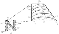
次に、第一の画像(3)を形成する第一の情報画線(4)について説明する。図2(a)は、第一の画像(3)の詳細を示す平面図である。第一の画像(3)は、少なくとも一つの第一の要素領域(3E)から成る。第一の要素領域(3E)は、それぞれが第一の画像(3)を構成するパーツであり、第一の要素領域(3E)は、第一の画像(3)である「N」の文字形状を形成している。例えば、第一の画像(3)は文字形状「N」で示す画像であり、太線で示す五つの第一の要素領域(3E1、3E2、3E3、3E4、3E5)から成る。なお、明確に説明するために、第一の要素領域(3E)を示す線を図示しているが、仮想の線であり、実際の第一の画像(3)には形成されない。また、第一の画像(3)に対する、第一の要素領域(3E)の分割方法の詳細については後述する。 Next, the first information image line (4) that forms the first image (3) will be described. FIG. 2A is a plan view showing details of the first image (3). The first image (3) consists of at least one first element region (3E). The first element region (3E) is a part that constitutes the first image (3), and the first element region (3E) is a letter “N” that is the first image (3). Form a shape. For example, the first image (3) is an image indicated by a character shape “N”, and includes five first element regions (3E 1 , 3E 2 , 3E 3 , 3E 4 , 3E 5 ) indicated by bold lines. For the sake of clarity, a line indicating the first element region (3E) is illustrated, but is a virtual line and is not formed in the actual first image (3). Details of the method of dividing the first element region (3E) for the first image (3) will be described later.
図2(b)は、図2(a)に示す一つの要素領域(3E2)の拡大図である。第一の要素領域(3E2)は、万線状に配置された、円弧状の第一の情報画線(4)から成る。第一の情報画線(4)は、第一のピッチ(P1)で複数形成されている。 FIG. 2B is an enlarged view of one element region (3E 2 ) shown in FIG. The first element region (3E 2 ) is composed of arc-shaped first information lines (4) arranged in a line. A plurality of first information lines (4) are formed at the first pitch (P1).
第一の要素領域(3E2)内に配置された第一の情報画線(4)において、始点(U)と終点(D)を結ぶ直線を基準線(H1)とした場合、基準線(H1)は同じ方向で万線状に配置される。その際、複数の第一の情報画線(4)において、基準線(H1)は平行となる。基準線(H1)を同じ方向とすることで、第一の情報画線(4)は、第一の要素領域(3E2)内において、直線状の第一の方向(X1)に配置される。 In the first information image line (4) arranged in the first element region (3E 2 ), when a straight line connecting the start point (U) and the end point (D) is the reference line (H1), the reference line ( H1) are arranged in a line in the same direction. At that time, the reference line (H1) is parallel in the plurality of first information image lines (4). By setting the reference line (H1) in the same direction, the first information image line (4) is arranged in the linear first direction (X1) in the first element region (3E 2 ). .
なお、図2では、第一の情報画線(4)の基準線(H1)を同じ方向として説明したが、異なる方向とすることも可能である。図3は、第一の情報画線(4)の他の配置形態を示す模式図である。図3に示す第一の要素領域(3E2)において、第一の情報画線(4)の基準線(H1a、H1b、H1c、H1d、H1e)は、異なる方向で万線状に配置される。例えば、基準線(H1a)を0度とした場合、基準線(H1a)に対して基準線(H1b)は5度、基準線(H1c)は10度、基準線(H1d)は15度、基準線(H1e)は20度である。 In FIG. 2, the reference line (H1) of the first information image line (4) has been described as the same direction, but it is also possible to have different directions. FIG. 3 is a schematic diagram showing another arrangement form of the first information image line (4). In the first element region (3E 2 ) shown in FIG. 3, the reference lines (H1a, H1b, H1c, H1d, H1e) of the first information image line (4) are arranged in different lines in different directions. . For example, when the reference line (H1a) is 0 degree, the reference line (H1b) is 5 degrees, the reference line (H1c) is 10 degrees, and the reference line (H1d) is 15 degrees with respect to the reference line (H1a). The line (H1e) is 20 degrees.
基準線(H1a、H1b、H1c、H1d、H1e)を異なる方向とすることで、例えば、図3(b)に示す複数の第一の情報画線(4)は、図内において、0度の基準線(H1a)に対して他の基準線(H1b、H1c、H1d、H1e)が徐々に傾いて配置される。 By setting the reference lines (H1a, H1b, H1c, H1d, H1e) in different directions, for example, the plurality of first information lines (4) shown in FIG. Other reference lines (H1b, H1c, H1d, H1e) are gradually inclined with respect to the reference line (H1a).
本発明の立体視可能な第一の画像(3)は、詳細については視認原理を説明する際に後述するが、基材(2)に対する観察角度を変化させることで、動的に視認することが可能である。 The first image (3) that can be viewed stereoscopically according to the present invention will be described later in detail when explaining the visual recognition principle, but can be dynamically viewed by changing the observation angle with respect to the base material (2). Is possible.
図2に示す、第一の情報画線(4)の基準線(H1)を同じ方向で万線状に配置された場合と、図3に示す、異なる方向で万線状に配置された場合では、基材(2)に対する観察角度を変化した時、画像の動き方が異なる。例えば、図2に示すように、基準線(H1)を同じ方向で万線状に配置した第一の画像(3)は、左右方向に動的に視認され、図3に示すように、基準線(H1)を異なる方向で万線状に配置した第一の画像(3)は、斜め方向に動的に視認される。 When the reference line (H1) of the first information image line (4) shown in FIG. 2 is arranged in a line in the same direction and in the case where the reference line (H1) is arranged in a different direction as shown in FIG. Then, when the observation angle with respect to the base material (2) is changed, the way the image moves is different. For example, as shown in FIG. 2, the first image (3) in which the reference lines (H1) are arranged in the same direction in the same line is dynamically visually recognized in the left-right direction, and as shown in FIG. The first image (3) in which the lines (H1) are arranged in different directions in different directions is dynamically visually recognized in an oblique direction.
なお、図3においては、第一の情報画線(4)の基準線(H1a、H1b、H1c、H1d、H1e)を、0〜20度の範囲内で徐々に傾けて配置したが、傾ける角度の範囲は前述範囲に限らない。 In FIG. 3, the reference lines (H1a, H1b, H1c, H1d, H1e) of the first information image line (4) are gradually inclined within a range of 0 to 20 degrees. The range is not limited to the above range.
詳細な視認原理については後述するが、本発明の立体視可能な第一の画像(3)は、定位置の光源に対して、第一の情報画線(4)において光輝性を有して視認される箇所が、観察角度の変化により第一の情報画線(4)上を移動することで、動的に視認可能となる。 Although the detailed visual principle will be described later, the stereoscopically viewable first image (3) of the present invention has glitter in the first information line (4) with respect to the light source at a fixed position. The visually recognizable portion moves on the first information line (4) due to the change in the observation angle, so that it can be visually recognized dynamically.
始点(U)における基準線(H1)に対する第一の情報画線(4)の接線(H2)が成す角度(θ1)と、終点(D)における基準線(H1)に対する第一の情報画線(4)の接線(H3)が成す角度(θ2)が大きい(90度に近い)場合、肉眼で定位置の光源に対して、第一の情報画線(4)上の光輝性を有して視認される範囲が大きくなる。よって、前述した傾ける角度の範囲も光輝性を有して視認される範囲に伴い、大きくなる。 The angle (θ1) formed by the tangent line (H2) of the first information image line (4) with respect to the reference line (H1) at the start point (U) and the first information image line with respect to the reference line (H1) at the end point (D). When the angle (θ2) formed by the tangent line (H3) of (4) is large (close to 90 degrees), it has the glitter on the first information line (4) with respect to the light source at a fixed position with the naked eye. The range that can be visually recognized increases. Therefore, the above-described tilt angle range also increases with the range that is visually recognized with glitter.
反対に、始点(U)における、基準線(H1)に対する第一の情報画線(4)の接線(H2)が成す角度(θ1)と、終点(D)における、基準線(H1)に対する第一の情報画線(4)の接線(H3)が成す角度(θ2)が小さい(0度に近い)場合、肉眼で定位置の光源に対して光輝性を有して視認される範囲が小さくなる。よって、前述した傾ける角度の範囲も光輝性を有して視認される範囲に伴い、小さくなる。 On the contrary, the angle (θ1) formed by the tangent line (H2) of the first information image line (4) with respect to the reference line (H1) at the start point (U) and the first point with respect to the reference line (H1) at the end point (D). When the angle (θ2) formed by the tangent line (H3) of one information image line (4) is small (close to 0 degree), the range visually recognized by the naked eye with respect to the light source at a fixed position is small. Become. Therefore, the range of the angle of inclination described above also decreases with the range visually recognized with glitter.
始点(U)における基準線(H1)に対する第一の情報画線(4)の接線(H2)が成す角度(θ1)と、終点(D)における基準線(H1)に対する第一の情報画線(4)の接線(H3)が成す角度(θ2)が大きい(90度に近い)場合、肉眼で定位置の光源に対して、第一の情報画線(4)上の光輝性を有して視認される範囲が大きくなる。よって、前述した傾ける角度の範囲も光輝性を有して視認される範囲に伴い、大きくなる。 The angle (θ1) formed by the tangent line (H2) of the first information image line (4) with respect to the reference line (H1) at the start point (U) and the first information image line with respect to the reference line (H1) at the end point (D). When the angle (θ2) formed by the tangent line (H3) of (4) is large (close to 90 degrees), it has the glitter on the first information line (4) with respect to the light source at a fixed position with the naked eye. The range that can be visually recognized increases. Therefore, the above-described tilt angle range also increases with the range that is visually recognized with glitter.
以上、複数の第一の情報画線(4)の基準線(H1a、H1b、H1c、H1d、H1e)を傾ける角度の範囲は、第一の画像(3)が立体視可能となるように、2〜90度の範囲内で、適宜設定することが可能である。 As described above, the range of angles for tilting the reference lines (H1a, H1b, H1c, H1d, H1e) of the plurality of first information image lines (4) is such that the first image (3) can be stereoscopically viewed. It can be appropriately set within a range of 2 to 90 degrees.
以下、本実施形態においては、第一の情報画線(4)の基準線(H1)を、図2に示した同じ方向である第一の方向(X1)に配置した場合について説明する。 Hereinafter, in the present embodiment, a case where the reference line (H1) of the first information image line (4) is arranged in the first direction (X1) which is the same direction shown in FIG. 2 will be described.
次に、第一の情報画線(4)を配置する第一のピッチ(P1)について説明する。第一のピッチ(P1)は、第一の情報画線(4)の形成方法、用いる基材(2)及び画線幅を考慮し、5〜1000μmの範囲内で適宜設定することが可能である。 Next, the first pitch (P1) for arranging the first information image line (4) will be described. The first pitch (P1) can be appropriately set within a range of 5 to 1000 μm in consideration of the formation method of the first information image line (4), the base material (2) to be used, and the image line width. is there.
第一のピッチ(P1)が5μm未満である場合には、基材(2)上に第一の情報画線(4)を形成しづらくなり、好ましくない。 When the first pitch (P1) is less than 5 μm, it is difficult to form the first information image line (4) on the substrate (2), which is not preferable.
反対に、第一のピッチ(P1)が1000μmを超える場合には、隣り合う第一の情報画線(4)間の光輝性を有しない領域が肉眼で視認可能となる。それにより、第一の画像(3)内において、光輝性を有しない面積が存在し、第一の画像(3)を立体的に視認する際の視認性が低下することから、好ましくない。 On the contrary, when the first pitch (P1) exceeds 1000 μm, a region having no glitter between the adjacent first information image lines (4) can be visually recognized. Thereby, there is an area having no glitter in the first image (3), and the visibility when the first image (3) is viewed three-dimensionally is not preferable.
なお、図2では、第一のピッチ(P1)を、すべて同じ規則的なピッチである第一のピッチ(P1)で図示しているが、ランダムなピッチとすることも可能である。 In FIG. 2, the first pitch (P1) is shown as the first pitch (P1), which is the same regular pitch, but may be a random pitch.
図4は、第一の情報画線(4)を第一の方向(X1)に配置した他の形態を示す平面図である。第一の情報画線(4)は、第一の方向(X1)に、ランダムなピッチ(PL)で配置されている。ランダムなピッチ(PL)で配置する場合には、その一つ一つのピッチは、前述した第一のピッチ(P1)の範囲と同様に、5〜1000μmの範囲内で適宜設定することが可能である。なお、ランダムなピッチ(PL)で配置した場合にも、第一の情報画線(4)は、第一の要素領域(3E)内に配置される。 FIG. 4 is a plan view showing another embodiment in which the first information image line (4) is arranged in the first direction (X1). The first information line (4) is arranged at a random pitch (PL) in the first direction (X1). In the case of arranging at a random pitch (PL), each of the pitches can be appropriately set within a range of 5 to 1000 μm, similarly to the range of the first pitch (P1) described above. is there. In addition, also when arrange | positioning with random pitch (PL), a 1st information image line (4) is arrange | positioned in a 1st element area | region (3E).
また、ピッチ(PL)を、5〜1000μmの範囲内とする理由については、前述した第一のピッチ(P1)と同様であることから説明を省略する。なお、立体視される画像の視認性を考慮すると、複数の第一の情報画線(4)から成る第一の画像(3)が均一な光輝性を有して視認されることが、好ましい。均一な光輝性を有して視認されることで、立体画像として視認しやすくなる。よって、第一の情報画線(4)のピッチは規則的な第一のピッチ(P1)で形成することが、好ましい。 The reason why the pitch (PL) is in the range of 5 to 1000 μm is the same as that of the first pitch (P1) described above, and thus the description thereof is omitted. In consideration of the visibility of the stereoscopically viewed image, it is preferable that the first image (3) including the plurality of first information image lines (4) is visually recognized with uniform brightness. . By being visually recognized with uniform brightness, it is easy to visually recognize as a stereoscopic image. Therefore, the pitch of the first information image line (4) is preferably formed at a regular first pitch (P1).
第一の情報画線(4)の画線幅は、第一のピッチ(P1)を考慮し、5〜1000μmの範囲内で適宜設定される。 The line width of the first information line (4) is appropriately set within a range of 5 to 1000 μm in consideration of the first pitch (P1).
画線幅が5μm未満である場合には、基材(2)上に第一の情報画線(4)を形成しづらいため、好ましくない。 When the image line width is less than 5 μm, it is difficult to form the first information image line (4) on the substrate (2), which is not preferable.
反対に、画線幅が1000μm以上である場合には、画線幅に対応して第一の画像(3)の形状も大きくする必要がある。第一の画像(3)を大きくした際には、第一の画像(3)を両眼視差により立体視しづらくなり、好ましくない。 On the contrary, when the image line width is 1000 μm or more, it is necessary to increase the shape of the first image (3) corresponding to the image line width. When the first image (3) is enlarged, it is difficult to stereoscopically view the first image (3) due to binocular parallax.
図5(a)は、図3に示す第一の情報画線(4)の一つを拡大した図である。第一の情報画線(4)は、前述のとおり、始点(U)、頂点(T)及び終点(D)を有する円弧状の画線である。 FIG. 5A is an enlarged view of one of the first information lines (4) shown in FIG. As described above, the first information image line (4) is an arc-shaped image line having a start point (U), a vertex (T), and an end point (D).
本発明の立体視可能な画像は、詳細については後述するが、基材(2)に対する観察角度を変化させることで、動的に視認することが可能である。動的に視認される理由は、基材(2)に対する観察角度を変化させることで、観察角度の変化に伴い、光輝性を有する第一の情報画線(4)の照明光を反射する箇所が変化するためである。第一の情報画線(4)を円弧状とすることで、第一の情報画線(4)の照明光を反射する箇所は、連続的に画線上を変化していく。よって、第一の画像(3)を動的に視認する際、第一の情報画線(4)を円弧状とすることで、第一の画像(3)は、連続的に動いているように視認される。 Although the details of the stereoscopically viewable image of the present invention will be described later in detail, it can be dynamically visually recognized by changing the observation angle with respect to the base material (2). The reason for dynamically recognizing is that the illumination angle of the first information image line (4) having glitter is reflected by changing the observation angle with respect to the base material (2). This is because of changes. By making the first information image line (4) into an arc shape, the portion of the first information image line (4) that reflects the illumination light continuously changes on the image line. Therefore, when the first image (3) is dynamically viewed, the first image (3) seems to move continuously by making the first information line (4) arc-shaped. Visible to.
第一の要素領域(3E)内に配置された第一の情報画線(4)において、始点(U)と終点(D)を結ぶ直線を基準線(H1)とした場合、始点(U)において、基準線(H1)に対する円弧状の第一の情報画線(4)の接線(H2)が成す角度(θ1)は、2〜90度の範囲内で、適宜設定することが可能である。 In the first information image line (4) arranged in the first element region (3E), when the straight line connecting the start point (U) and the end point (D) is the reference line (H1), the start point (U) , The angle (θ1) formed by the tangent line (H2) of the arc-shaped first information image line (4) with respect to the reference line (H1) can be appropriately set within a range of 2 to 90 degrees. .
詳細については後述するが、第一の画像(3)は、第一の情報画線(4)の始点(U)と終点(D)間とで、光源からの入射光は両眼視差が可能な範囲内において、異なる方向に反射することで、立体画像として視認される。始点(U)において、基準線(H1)に対する円弧状の第一の情報画線(4)の接線(H2)が成す角度(θ1)が2度未満である場合には、光源からの反射光が、ほぼ同じ方向に反射するため、適当な観察距離において両眼視差が不可能となり、好ましくない。 Although details will be described later, in the first image (3), the binocular parallax is possible for the incident light from the light source between the start point (U) and the end point (D) of the first information image line (4). In such a range, it is visually recognized as a stereoscopic image by reflecting in different directions. When the angle (θ1) formed by the tangent line (H2) of the arc-shaped first information image line (4) with respect to the reference line (H1) at the start point (U) is less than 2 degrees, the reflected light from the light source However, since it reflects in substantially the same direction, binocular parallax becomes impossible at an appropriate observation distance, which is not preferable.
反対に、始点(U)において、基準線(H1)に対する円弧状の第一の情報画線(4)の接線(H2)が成す角度(θ1)が90度を超える場合には、始点(U)側と、終点(D)側とで、異なる方向に入射光は反射するが、両眼視差可能な範囲外となるため、好ましくない。 Conversely, when the angle (θ1) formed by the tangent line (H2) of the arc-shaped first information image line (4) with respect to the reference line (H1) at the start point (U) exceeds 90 degrees, the start point (U ) Side and the end point (D) side, incident light is reflected in different directions, but this is not preferable because it falls outside the binocular parallax range.
また、終点(D)において、基準線(H1)に対する円弧状の第一の情報画線(4)の接線(H3)が成す角度(θ2)においても、前述の始点(U)側と同様の理由から、2〜90度の範囲内で、適宜設定することが可能である。 Further, at the end point (D), the angle (θ2) formed by the tangent line (H3) of the arc-shaped first information image line (4) with respect to the reference line (H1) is the same as the above-mentioned start point (U) side. For the reason, it can be appropriately set within a range of 2 to 90 degrees.
第一の要素領域(3E)内に配置された第一の情報画線(4)は、始点(U)において、基準線(H1)と基準線(H1)に対する第一の情報画線(4)の接線(H2)が成す角度(θ1)とは、すべての第一の情報画線(4)において、同じであることが好ましい。また、終点(D)において、基準線(H1)と基準線(H1)に対する第一の情報画線(4)の接線(H3)は成す角度(θ2)においても、すべての第一の情報画線(4)において、同じ角度とすることが、好ましい。 The first information image line (4) arranged in the first element region (3E) is the first information image line (4) with respect to the reference line (H1) and the reference line (H1) at the start point (U). The angle (θ1) formed by the tangent line (H2) is preferably the same in all the first information image lines (4). Further, at the end point (D), all the first information images are also obtained at the angle (θ2) formed by the reference line (H1) and the tangent line (H3) of the first information image line (4) with respect to the reference line (H1). In line (4), it is preferable to make it the same angle.
前述のとおり、第一の情報画線(4)は、第一の要素領域(3E)内に配置される。第一の画像(3)を両眼視差により立体視する際に、始点(U)側の角度(θ1)と、終点(D)側の角度(θ2)が同じ角度である場合、第一の情報画線(4)からの反射光の方向はすべての第一の情報画線(4)において、同一方向となる。よって、肉眼において、明瞭に第一の画像(3)を視認することが可能となる。一方、始点(U)側の角度(θ1)と、終点(D)側の角度(θ2)が異なる角度である場合、第一の情報画線(4)からの反射光の方向にバラつきが生じる。それにより、第一の画像(3)はぼやけた画像として視認され、好ましくない。 As described above, the first information line (4) is arranged in the first element region (3E). When the first image (3) is stereoscopically viewed with binocular parallax, if the angle (θ1) on the start point (U) side and the angle (θ2) on the end point (D) side are the same angle, The direction of the reflected light from the information image line (4) is the same in all the first information image lines (4). Therefore, the first image (3) can be clearly visually recognized with the naked eye. On the other hand, when the angle (θ1) on the start point (U) side and the angle (θ2) on the end point (D) side are different, the direction of reflected light from the first information image line (4) varies. . Thereby, the first image (3) is visually recognized as a blurred image, which is not preferable.
また、他の第一の情報画線(4)の、好ましい配置としては、図6(a)に示すように、第一の要素領域(3E)において、第一の要素領域(3E)内に配置された、複数の第一の情報画線(4)の各基準線(H1)の中心を結ぶ仮想線(J)上に第一の情報画線の頂点(T)が配置されるか、又は、図6(b)に示すように、仮想線(J)に対して始点(U)側及び終点(D)側の左右一方に第一の情報画線(4)の頂点(T)が配置されることが、好ましい。 Moreover, as a preferable arrangement of the other first information image line (4), as shown in FIG. 6A, in the first element region (3E), in the first element region (3E). The vertex (T) of the first information line is arranged on a virtual line (J) that connects the centers of the reference lines (H1) of the plurality of first information lines (4) that are arranged, Alternatively, as shown in FIG. 6B, the vertex (T) of the first information image line (4) is on the left or right side of the start point (U) side and the end point (D) side with respect to the virtual line (J). It is preferable that they are arranged.
図6(a)に示す構成とすることで、第一の画像(3)を両眼視差により立体視する際に、始点(U)側の角度(θ1)と、終点(D)側の角度(θ2)が同じ角度である場合、第一の情報画線(4)からの反射光の方向はすべての第一の情報画線(4)において、同一方向となり、肉眼において、明瞭に第一の画像(3)を視認することが可能となる。 With the configuration shown in FIG. 6A, when stereoscopically viewing the first image (3) with binocular parallax, the angle (θ1) on the start point (U) side and the angle on the end point (D) side When (θ2) is the same angle, the direction of the reflected light from the first information image line (4) is the same in all the first information image lines (4), and is clearly the first for the naked eye. It is possible to visually recognize the image (3).
また、図6(b)に示す構成とすることで、始点(U)側の角度(θ1)と、終点(D)側の角度(θ2)は異なる角度であるが、始点(U)側の角度(θ1)と終点(D)側の角度が、仮想線(J)に対して左右すべてにおいて、大小関係が発生する。例えば、図6(b)においては、仮想線(J)に対して、左側にすべての頂点(T)が配置されている。それにより、第一の要素領域(3E)内に配置された第一の情報画線(4)の始点(U)側の角度(θ1)は、終点(D)側の角度(θ2)より大きくなる。それにより、第一の情報画線(4)からの反射光の方向にバラつきが、あまり生じることなく、第一の画像(3)は明瞭に視認することが不可能となる。 6B, the angle (θ1) on the start point (U) side and the angle (θ2) on the end point (D) side are different from each other, but the angle on the start point (U) side is different. There is a magnitude relationship between the angle (θ1) and the angle on the end point (D) side on both the left and right sides of the virtual line (J). For example, in FIG. 6B, all the vertices (T) are arranged on the left side with respect to the virtual line (J). Thereby, the angle (θ1) on the start point (U) side of the first information image line (4) arranged in the first element region (3E) is larger than the angle (θ2) on the end point (D) side. Become. As a result, the first image (3) cannot be clearly seen without much variation in the direction of reflected light from the first information image line (4).
以下、本実施の形態においては、始点(U)における基準線(H1)に対する第一の情報画線(4)の接線(H2)が成す角度(θ1)と、終点(D)における基準線(H1)に対する第一の情報画線(4)の接線(H3)が成す角度(θ2)を、それぞれ基材(2)上に複数配置された、すべての第一の情報画線(4)において、同じ角度として説明する。 Hereinafter, in the present embodiment, the angle (θ1) formed by the tangent line (H2) of the first information image line (4) with respect to the reference line (H1) at the start point (U) and the reference line at the end point (D) ( The angle (θ2) formed by the tangent line (H3) of the first information line (4) with respect to H1) is plural for each of the first information lines (4) arranged on the substrate (2). This will be described as the same angle.
基準線(H1)の長さは、第一の画像(3)の大きさや、第一の画像(3)と観察者との距離に合わせて適宜設定するが、0.5〜65mmの範囲内とすることが、好ましい。本発明の第一の画像(3)は、両眼視差を用いることで、立体視することが可能な画像である。一般的な人間の両目間の距離である65mm以下に留めなければならない。また、万人がそれと感じる適当な遠近感を生み出すためには、0.5mm以上の所定距離で形成する必要がある。よって、基準線(H1)の長さを、前述の範囲内とすることで、両眼視差により第一の画像(3)を視認しやすくなる。 The length of the reference line (H1) is appropriately set according to the size of the first image (3) and the distance between the first image (3) and the observer, but is within the range of 0.5 to 65 mm. Is preferable. The first image (3) of the present invention is an image that can be stereoscopically viewed using binocular parallax. It must be kept below 65 mm, which is the distance between both eyes of a general human being. In addition, in order to create an appropriate sense of perspective that everyone feels like this, it is necessary to form it at a predetermined distance of 0.5 mm or more. Therefore, by setting the length of the reference line (H1) within the above-described range, the first image (3) can be easily viewed by binocular parallax.
なお、形成体(1)を、セキュリティ製品等に用いる場合には、小さい方が改竄しづらく、偽造防止効果が向上することから、基準線(H1)の長さは、短い方が、好ましい。 When the formed body (1) is used for a security product or the like, the smaller one is more difficult to tamper with and the forgery prevention effect is improved. Therefore, the shorter reference line (H1) is preferable.
また、形成体(1)を、ポスター、広告物等に意匠性の向上を目的として用いる場合には、形成体(1)が大きいことから、形成体(1)の大きさの変化に伴い、基準線(H1)の長さが長くなる。よって、ポスター、形成体(1)と観察者との距離により、適宜基準線(H1)の長さは、前述した範囲に限らず適宜設定する。 In addition, when the formed body (1) is used for the purpose of improving the designability in posters, advertisements, etc., since the formed body (1) is large, with the change in the size of the formed body (1), The length of the reference line (H1) becomes longer. Therefore, the length of the reference line (H1) is appropriately set according to the distance between the poster and the formed body (1) and the observer, not limited to the above range.
以上のように、形成体(1)の大きさ、用途及び観察者と形成体(1)の距離に合わせて、第一の画像(3)が立体画像として視認可能となるように、適宜基準線(H1)の長さを設定する。 As described above, according to the size and use of the formed body (1) and the distance between the observer and the formed body (1), the first image (3) can be appropriately selected so as to be visible as a stereoscopic image. Set the length of the line (H1).
なお、図6(a)では、第一の情報画線(4)は頂点(T)を中心とし、左右対称の形状として図示しているが、左右非対称とすることも可能である。 In FIG. 6A, the first information image line (4) is illustrated as a bilaterally symmetric shape with the vertex (T) as the center, but it can also be bilaterally asymmetric.
図6(b)は、第一の情報画線(4)の他の形状を示す拡大図である。第一の情報画線(4)は、頂点(T)を中心とし、左右非対称の形状としている。左右非対称の形状とした場合には、始点(U)における基準線(H1)に対する第一の情報画線(4)の接線(H2)が成す角度(θ1)と、終点(D)における基準線(H1)に対する第一の情報画線(4)の接線(H3)が成す角度(θ2)は、前述した角度の範囲と同様に、それぞれ2〜90度の範囲内で適宜設定することが可能である。以下、本実施の形態においては、第一の情報画線(4)は図6(a)に示す形状として説明する。 FIG. 6B is an enlarged view showing another shape of the first information image line (4). The first information line (4) has an asymmetric shape with the vertex (T) as the center. In the case of a left-right asymmetric shape, the angle (θ1) formed by the tangent line (H2) of the first information image line (4) to the reference line (H1) at the start point (U) and the reference line at the end point (D) The angle (θ2) formed by the tangent line (H3) of the first information image line (4) with respect to (H1) can be set as appropriate within a range of 2 to 90 degrees, similarly to the angle range described above. It is. Hereinafter, in the present embodiment, the first information image line (4) will be described as the shape shown in FIG.
なお、第一の画像(3)は、前述した文字形状に限らず、第一の情報画線(4)を複数配置することが可能であれば、特段限定はされない。図7は、第一の画像(3)の他の形状を示す平面図である。第一の画像(3)は、図7(a)に示す、円形状や、図7(b)に示す、文字形状「A」や、図7(c)に示す顔形状とすることも可能である。図7(a)、図7(b)及び図7(c)においても、第一の要素領域(3E)は太線に示すように、第一の画像(3)を構成するパーツそれぞれをいい、第一の画像(3)が立体視可能とするように、適宜形成する。 The first image (3) is not limited to the character shape described above, and is not particularly limited as long as a plurality of first information image lines (4) can be arranged. FIG. 7 is a plan view showing another shape of the first image (3). The first image (3) may have a circular shape shown in FIG. 7A, a character shape “A” shown in FIG. 7B, or a face shape shown in FIG. 7C. It is. In FIG. 7A, FIG. 7B and FIG. 7C, the first element region (3E) refers to each of the parts constituting the first image (3), as shown by the bold line. It forms suitably so that a 1st image (3) can be viewed stereoscopically.
なお、好ましくは、第一の画像(3)を形成する複数の第一の情報画線(4)の各基準線(H1)の中心を結ぶ仮想線(J)が、一つの第一の要素領域(3E)内で一本となるように、第一の画像(3)を第一の要素領域(3E)に分割する。 Preferably, a virtual line (J) connecting the centers of the reference lines (H1) of the plurality of first information lines (4) forming the first image (3) is one first element. The first image (3) is divided into first element regions (3E) so as to become one in the region (3E).
例えば、図7(a)において、第一の画像(3)を形成する複数の第一の情報画線(4)の各基準線(H1)の中心を結ぶ仮想線(J)は一本である。よって、第一の画像(3)は、一つの第一の要素領域(3E)から構成される。 For example, in FIG. 7A, there is one virtual line (J) connecting the centers of the reference lines (H1) of the plurality of first information lines (4) forming the first image (3). is there. Therefore, the first image (3) is composed of one first element region (3E).
また、図7(b)において、第一の画像(3)を形成する複数の第一の情報画線(4)を、第一の要素領域(3E1)の下側から配置した場合、第一の情報画線(4)の配列が崩れる箇所が発生する。この配列が崩れる箇所を、第一の要素領域(3E2)に示すように分割することで、各要素領域(3E)内において、各基準線(H1)の中心を結ぶ仮想線(J)が一本となり、第一の画像(3)は、立体視可能な画像となる。 In FIG. 7B, when a plurality of first information lines (4) forming the first image (3) are arranged from the lower side of the first element region (3E 1 ), The location where the arrangement of one information line (4) is broken occurs. By dividing the location where the arrangement is broken as shown in the first element region (3E 2 ), a virtual line (J) connecting the centers of the reference lines (H1) is formed in each element region (3E). The first image (3) is a stereoscopically viewable image.
なお、複数の第一の要素領域(3E)は、領域ごとに異なる方向に第一の情報画線(4)を配置することも可能である。 In the plurality of first element regions (3E), the first information lines (4) can be arranged in different directions for each region.
例えば、図7(c)に示す第一の画像(3)は、第一の要素領域(3E)である目、鼻及び口の、それぞれの要素領域(3E)内において、第一の情報画線(H1)の基準線は、いずれも直線状の第一の方向で配置されているが、目をX11の方向(X11)で配置し、鼻をX12の方向(X12)で配置し、口をX13の方向(X13)で配置し、X11の方向(X11)、X12の方向(X12)及びX13の方向(X13)を互いに異なる方向とすることも可能である。 For example, the first image (3) shown in FIG. 7C is a first information image in each element region (3E) of the eyes, nose and mouth which are the first element regions (3E). reference line of the line (H1), which both are arranged in a first direction straight, eyes arranged at X1 1 direction (X1 1), nose and X1 2 direction (X1 2) And the mouth is arranged in the X1 3 direction (X1 3 ), and the X1 1 direction (X1 1 ), the X1 2 direction (X1 2 ), and the X1 3 direction (X1 3 ) are different from each other. Is also possible.
また。図3において説明したように、本発明の形成体(S)は、一つの第一の要素領域(3E)内において、第一の情報画線(4)の基準線(H1)は異なる方向とすることも可能である。 Also. As described with reference to FIG. 3, in the formed body (S) of the present invention, the reference line (H1) of the first information image line (4) is in a different direction within one first element region (3E). It is also possible to do.
例えば、図7(c)に示す第一の画像(3)において、第一の要素領域(3E)である目(3E1)、鼻(3E2)及び口(3E3)において、目は第一の情報画線(4)の基準線(H1)を図3において前述した異なる方向で配置し、鼻(3E2)及び口(3E3)は、図2において前述した基準線(H1)を同じ方向で配置することも可能である。 For example, in the first image (3) shown in FIG. 7 (c), in the eyes (3E 1 ), nose (3E 2 ) and mouth (3E 3 ) which are the first element regions (3E), the eyes The reference line (H1) of one information line (4) is arranged in the different direction described above in FIG. 3, and the nose (3E 2 ) and the mouth (3E 3 ) have the reference line (H1) described in FIG. It is also possible to arrange them in the same direction.
基準線(H1)が同じ方向で配列した要素領域(3E)と、異なる方向で配列した要素領域(3E)は、観察角度の変化により、互いに異なる方向に動的に視認される。よって、図7(c)においては、鼻及び口は同じ方向に動的に視認されるが、目は鼻及び口とは異なる方向に動的に視認され、第一の画像(3)は、より複雑に動的に視認される。 The element region (3E) in which the reference lines (H1) are arranged in the same direction and the element region (3E) in which the reference line (H1) is arranged in different directions are dynamically visually recognized in different directions due to a change in observation angle. Thus, in FIG. 7C, the nose and mouth are dynamically viewed in the same direction, but the eyes are dynamically viewed in a direction different from the nose and mouth, and the first image (3) is More complex and dynamic.
次に、第一の情報画線(4)の画線深度と、第一の情報画線(4)を形成する透明基体(2a)と関係について説明する。第一の情報画線(4)は、段落(0019)にて説明した光輝性を有する画線、すなわち、色彩層(2b、2c)を完全に除去し、かつ、光を透過する明暗フリップフロップ性を有する材料である透明基体(2a)の一部を除去して凹形状に加工することにより形成した画線である。 Next, the relationship between the depth of the first information image line (4) and the transparent substrate (2a) forming the first information image line (4) will be described. The first information image line (4) is a bright and dark flip-flop that completely removes the image line having the glitter described in paragraph (0019), that is, the color layers (2b, 2c) and transmits light. It is an image line formed by removing a part of the transparent substrate (2a), which is a material having a property, and processing it into a concave shape.
透明基体(2a)を凹形状に変形させて形成する方法とは、透明基体(2a)を、レーザ加工、切削加工等基材(2)を変形することが可能な公知の加工機を用いて、第一の情報画線(4)の形状に合わせて加工することで形成される。例えば、図8(a)に示す第一の色彩層(2b)、透明基体(2a)、第二の色彩層(2c)から成る三層構造の基材(2)に対し、レーザ加工、切削加工により色彩層(2b、2c)を完全に除去し、かつ、光を透過する明暗フリップフロップ性を有する材料である透明基体(2a)の一部を除去して、凹形状に加工することで第一の情報画線(4)を形成した場合は、図8(b)に示すように、レーザ加工により形成した第一の情報画線(4a)の形状は、レーザの熱分布に依存し、鋭利な刃物を持つ数値制御式加工機械(NC加工機)により切削加工して形成した第一の情報画線(4b、4c)の断面形状は、刃物の形状となる。なお、第一の情報画線(4a)の形状は、滑らかな曲面を有することが好ましい。断面形状が、前述した形状を取ることにより、輝点の動き方が曲面に沿うことにより滑らかとなる。 The method of forming the transparent substrate (2a) by deforming it into a concave shape means that the transparent substrate (2a) is formed using a known processing machine capable of deforming the substrate (2) such as laser processing or cutting. It is formed by processing according to the shape of the first information image line (4). For example, laser processing and cutting are performed on a base material (2) having a three-layer structure including a first color layer (2b), a transparent substrate (2a), and a second color layer (2c) shown in FIG. By completely removing the color layers (2b, 2c) by processing, and removing a part of the transparent substrate (2a), which is a material having light and dark flip-flops that transmits light, and processing into a concave shape When the first information line (4) is formed, as shown in FIG. 8B, the shape of the first information line (4a) formed by laser processing depends on the heat distribution of the laser. The cross-sectional shape of the first information lines (4b, 4c) formed by cutting with a numerically controlled processing machine (NC processing machine) having a sharp blade is the shape of the blade. Note that the shape of the first information image line (4a) preferably has a smooth curved surface. When the cross-sectional shape takes the shape described above, the bright spot moves smoothly along the curved surface.
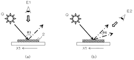
次に、前述した第一の画像(3)を視認するための観察角度について説明する。図9は、形成体(1)が付与された基材(2)を観察するための視点(E1、E2)を示す図である。なお、第一の情報画線(4)は、基材(2)上における第一の方向(X1)に配置されている。 Next, the observation angle for visually recognizing the first image (3) described above will be described. FIG. 9 is a diagram showing viewpoints (E1, E2) for observing the base material (2) to which the formed body (1) is applied. In addition, the 1st information image line (4) is arrange | positioned in the 1st direction (X1) on a base material (2).
本発明においては、基材(2)、定位置の光源(Q)及び視点が図9(a)に示す位置関係にあるとき、第一の観察角度(E1)から観察したとし、図9(b)に示す位置関係にあるとき、第二の観察角度(E2)から観察したとする。 In the present invention, when the base material (2), the light source (Q) at a fixed position, and the viewpoint are in the positional relationship shown in FIG. 9 (a), it is observed from the first observation angle (E1). Assume that the observation is performed from the second observation angle (E2) when the positional relationship shown in b) is satisfied.
第一の観察角度(E1)とは、第一の情報画線(4)が定位置の光源(Q)からの入射光に対して、光輝性を有して視認されない領域のことである。例えば、第一の情報画線(4)を、プラスチック等の透明樹脂で形成した場合、拡散反射領域においては、光源(Q)からの入射光を反射しない。よって、第一の情報画線(4)は、所定の反射光量未満の反射光であり、肉眼において光輝性を有しない画線として視認される。 The first observation angle (E1) is a region in which the first information image line (4) is not visually recognized with brilliancy with respect to incident light from the light source (Q) at a fixed position. For example, when the first information image line (4) is formed of a transparent resin such as plastic, incident light from the light source (Q) is not reflected in the diffuse reflection region. Therefore, the first information image line (4) is reflected light having a light amount less than a predetermined amount of reflected light, and is visually recognized as an image line having no glitter with the naked eye.
第二の観察角度(E2)とは、第一の情報画線(4)が定位置の光源(Q)からの入射光に対して、光輝性を有して視認される領域のことである。例えば、第一の情報画線(4)を、透明なプラスチック樹脂で形成した場合、正反射領域においては、光源(Q)からの入射光を反射する。よって、第一の情報画線(4)は、所定の反射光量以上の反射光を有し、肉眼において光輝性を有する画線として視認される。 The second observation angle (E2) is a region where the first information image line (4) is visually recognized with a brilliancy with respect to the incident light from the light source (Q) at a fixed position. . For example, when the first information image line (4) is formed of a transparent plastic resin, incident light from the light source (Q) is reflected in the regular reflection region. Therefore, the first information image line (4) has reflected light that is greater than or equal to a predetermined amount of reflected light, and is visually recognized as an image line that has a glittering property with the naked eye.
なお、第一の観察角度(E1)及び第二の観察角度(E2)は、第一の情報画線(4)を形成する材料により、基材(2)、光源(Q)及び始点の位置関係は変化し、更には、正反射領域及び拡散反射領域に限らない。前述のとおり、本発明における第一の観察角度(E1)とは、第一の情報画線(4)が定位置の光源(Q)からの入射光に対して、光輝性を有して視認されない領域のことであり、第二の観察角度(E2)とは、第一の情報画線(4)が定位置の光源(Q)からの入射光に対して、光輝性を有して視認される領域のことである。 Note that the first observation angle (E1) and the second observation angle (E2) are the positions of the base material (2), the light source (Q), and the starting point depending on the material forming the first information image line (4). The relationship changes and is not limited to the regular reflection region and the diffuse reflection region. As described above, the first observation angle (E1) in the present invention means that the first information image line (4) is visually recognized with the radiance to the incident light from the light source (Q) at a fixed position. The second observation angle (E2) is a region where the first information image line (4) is visually recognized with respect to incident light from the light source (Q) at a fixed position. It is an area to be done.
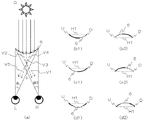
図10は、第二の観察角度(E2)における第一の情報画線(4)の視認原理を示す模式図である。図10(a)に示すように、第二の観察角度(E2)において、第一の情報画線(4)を形成する、光輝性を有する材料は、光源(Q)からの入射光を反射する。 FIG. 10 is a schematic diagram showing the visual recognition principle of the first information image line (4) at the second observation angle (E2). As shown in FIG. 10A, at the second observation angle (E2), the glittering material forming the first information image line (4) reflects the incident light from the light source (Q). To do.
前述のとおり、本発明の第一の情報画線(4)は、基材(2)に対して凹形状又は凸形状の円弧状画線である。よって、光源(Q)からの反射光(V1、V2、V3、V4、V5)は、一方向ではなく、他方向に反射する。 As described above, the first information line (4) of the present invention is a concave or convex arcuate line with respect to the substrate (2). Therefore, the reflected light (V1, V2, V3, V4, V5) from the light source (Q) is reflected not in one direction but in the other direction.
観察者の左目(L)の視野角度はθLであることから、左目(L)には、視野角度θL内にある反射光(V1、V2)は視認される。一方、反射光(V3、V4、V5)は、視野角度θLの範囲外であることから、視認されない。よって、第一の情報画線(4)は、観察者の左目(L)には、図10(b)に示すように、視野角度θL内となる始点(U)側の点線部は、光輝性を有して視認されるが、視野角度θL外となる終点(D)側の実線部は、光輝性を有しない画線として視認される。 Since the viewing angle of the left eye (L) of the observer is θL, the reflected light (V1, V2) within the viewing angle θL is visually recognized by the left eye (L). On the other hand, the reflected light (V3, V4, V5) is not visually recognized because it is outside the range of the viewing angle θL. Therefore, as shown in FIG. 10B, the first information image line (4) is a bright line on the left eye (L) of the observer, as shown in FIG. 10 (b). However, the solid line portion on the end point (D) side outside the viewing angle θL is visually recognized as an image line having no glitter.
一方、観察者の右目(R)の視野角度はθRであることから、右目(R)には、視野角度θR内にある反射光(V4、V5)が視認される。一方、反射光(V1、V2、V3)は、視野角度θRの範囲外であることから、視認されない。よって、第一の情報画線(4)は、観察者の右目(R)には、図10(c)に示すように、視野角度θR内となる終点(D)側の点線部は光輝性を有して視認されるが、視野角度θR外となる始点(U)側の実線部は光輝性を有しない画線として視認される。 On the other hand, since the viewing angle of the right eye (R) of the observer is θR, reflected light (V4, V5) within the viewing angle θR is visually recognized by the right eye (R). On the other hand, the reflected light (V1, V2, V3) is not visually recognized because it is outside the range of the viewing angle θR. Therefore, as shown in FIG. 10C, the first information image line (4) has a glitter on the right side (R) of the observer, as shown in FIG. 10C. However, the solid line portion on the start point (U) side outside the viewing angle θR is visually recognized as an image line having no glitter.
図10(b)に示す左目(L)で視認される第一の情報画線(4)の光輝性を有して視認される箇所と、図10(c)に示す右目(R)で視認される第一の情報画線(4)の光輝性を有して視認される箇所は、左右の視点を結ぶ線(G)に対して、左右に位相差を持った画線として視認される。よって、同一画像を複数並んで形成しなくも、両眼視差により、観察者には、図10(d)に示すように、第一の情報画線(4)は、立体画線として視認される。 A portion visually recognized by the first information image line (4) visually recognized by the left eye (L) shown in FIG. 10B and visually recognized by the right eye (R) shown in FIG. The portion that is visually recognized with the glitter of the first information image line (4) is visually recognized as an image line having a phase difference on the left and right with respect to the line (G) connecting the left and right viewpoints. . Therefore, even if the same image is not formed in a row, the first information image line (4) is visually recognized as a three-dimensional image line by the binocular parallax as shown in FIG. The
なお、形成体(1)が、図2に示した基準線(H1)を同じ方向とした第一の情報画線(4)から成る場合、図10(a)に示す、左右の視点を結ぶ線(G)と、基準線(H1)が略平行となるように観察することで、第一の情報画線(4)及び後述する第一の画像(3)を立体的に視認することが可能となる。 When the formed body (1) is composed of the first information image line (4) with the reference line (H1) shown in FIG. 2 in the same direction, the left and right viewpoints shown in FIG. 10 (a) are connected. By observing the line (G) and the reference line (H1) to be substantially parallel, the first information image line (4) and a first image (3) to be described later can be viewed in three dimensions. It becomes possible.
なお、形成体(1)が、図3に示した基準線(H1)を異なる方向とした第一の情報画線(4)から成る場合、例えば、図3に示した基準線(H1a)を0度、基準線(H1b)を5度、基準線(H1c)を10度、基準線(H1d)を15度及び基準線(H1e)を20度とした場合には、観察者の右目(R)の視野角度θRと、左目の視野角度θLの範囲内に、異なる方向に配置した基準線の最小角度(図4においては、基準線(H1a)の0度が最小角度)と最大角度(図3においては、基準線(H1e)の20度が最大角度)に視認可能となるように、形成体(1)と観察者の目の距離とを適宜調節する。 In the case where the formed body (1) is composed of the first information image line (4) having the reference line (H1) shown in FIG. 3 in a different direction, for example, the reference line (H1a) shown in FIG. If the reference line (H1b) is 0 degree, the reference line (H1c) is 10 degrees, the reference line (H1d) is 15 degrees, and the reference line (H1e) is 20 degrees, the observer's right eye (R ) And a left-eye viewing angle θL within the range of the viewing angle θR and the minimum angle of the reference line arranged in different directions (in FIG. 4, 0 degree of the reference line (H1a) is the minimum angle) and the maximum angle (FIG. 3, the distance between the formed body (1) and the eyes of the observer is adjusted as appropriate so that the reference line (H1e) can be visually recognized at the maximum angle of 20 degrees.
次に、形成体(1)を、各観察角度(E1、E2)から観察した際の視認原理について説明する。 Next, the visual recognition principle when the formed body (1) is observed from each observation angle (E1, E2) will be described.
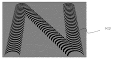
図11は、第一の情報画線(4)における基準線が、同じ方向で万線状に配置された形成体(1)を、第一の観察角度(E1)から観察した際の平面図である。基材(2)に対して第一の観察角度(E1)から観察した場合、第一の情報画線(4)は、光輝性を有しない画線として視認される。よって、複数の第一の情報画線(4)から成る第一の画像(3)は、平面的な画像として視認される。 FIG. 11 is a plan view when the formation body (1) in which the reference lines in the first information image line (4) are arranged in a line in the same direction is observed from the first observation angle (E1). It is. When observed from the first observation angle (E1) with respect to the substrate (2), the first information image line (4) is visually recognized as an image line having no glitter. Therefore, the first image (3) including the plurality of first information lines (4) is visually recognized as a planar image.
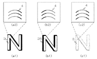
図12は、図11に示す形成体(1)を、第二の観察角度(E2)から観察した際の平面図である。基材(2)に対して第二の観察角度(E2)から観察した場合、第一の情報画線(4)は、光輝性を有する画線として視認される。 FIG. 12 is a plan view when the formed body (1) shown in FIG. 11 is observed from the second observation angle (E2). When observed from the second observation angle (E2) with respect to the substrate (2), the first information image line (4) is visually recognized as an image line having glitter.
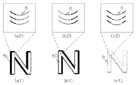
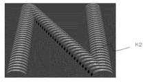
図12(a1)は、観察者の左目(L)に視認される第一Lの画像(3L)を示す平面図であり、図12(a2)は、図12(a1)の一部を拡大した図である。図12(a2)に示すように、第二の観察角度(E2)において観察者の左目(L)には、第一の情報画線(4)における点線部が光輝性を有して視認され、実線部は、光輝性を有しない画線として視認される。よって、観察者の左目(L)には、図12(a2)に示す、複数の第一の情報画線(4)における、光輝性を有して視認される箇所から成る第一Lの画像(3L)が視認される。 FIG. 12A1 is a plan view showing a first L image (3L) visually recognized by the left eye (L) of the observer, and FIG. 12A2 is an enlarged view of a part of FIG. 12A1. FIG. As shown in FIG. 12 (a2), at the second observation angle (E2), the left eye (L) of the observer visually recognizes the dotted line portion in the first information image line (4) with glitter. The solid line portion is visually recognized as an image line having no glitter. Therefore, in the left eye (L) of the observer, the first L image composed of the portions of the plurality of first information image lines (4) shown in FIG. (3L) is visually recognized.
図12(b1)は、観察者の右目(R)に視認される第一Rの画像(3R)を示す平面図であり、図12(b2)は、図12(b1)の一部を拡大した図である。図12(b2)に示すように、第二の観察角度(E2)において観察者の右目(R)には、第一の情報画線(4)における点線部が光輝性を有して視認され、実線部は、光輝性を有しない画線として視認される。よって、観察者の右目(R)には、図12(b2)に示す、複数の第一の情報画線(4)における、光輝性を有して視認される箇所から成る第一Rの画像(3R)が視認される。 FIG. 12 (b1) is a plan view showing a first R image (3R) visually recognized by the observer's right eye (R), and FIG. 12 (b2) is an enlarged view of part of FIG. 12 (b1). FIG. As shown in FIG. 12 (b2), at the second observation angle (E2), the dotted line portion in the first information image line (4) is visually recognized by the viewer's right eye (R) with glitter. The solid line portion is visually recognized as an image line having no glitter. Therefore, in the right eye (R) of the observer, the first R image made up of the portions that are visually recognized with brilliancy in the plurality of first information image lines (4) shown in FIG. 12 (b2). (3R) is visually recognized.
図12(c1)は、観察者の両目(L、R)に視認される第一の画像(3)を示す平面図であり、図12(c2)は、図12(c1)の一部を拡大した図である。前述したように、第二の観察角度(E2)において観察者の左目(L)には、図12(a1)に示す第一Lの画像(3L)が視認され、右目(R)には、図12(b1)に示す第一Rの画像(3R)が視認される。 FIG. 12 (c1) is a plan view showing the first image (3) visually recognized by both eyes (L, R) of the observer, and FIG. 12 (c2) is a part of FIG. 12 (c1). FIG. As described above, the first L image (3L) shown in FIG. 12A1 is visually recognized in the left eye (L) of the observer at the second observation angle (E2), and the right eye (R) The first R image (3R) shown in FIG.
前述のとおり、左目(L)で視認される第一の情報画線(4)と、右目で視認される第一の情報画線(4)は、始点(U)と終点(D)を結ぶ直線である基準線(H1)に対して、位相差を持った画線として視認されることから、第一Rの画像(3R)と、第一Lの画像(3L)においても、基準線(H1)に対して位相差を持った画像として観察者の両目(L、R)にそれぞれ視認される。よって、右目で視認される第一の画像(3)と、左目で視認される第一の画像(3)の位相が異なることで、両眼視差により観察者には色彩層の色彩から成る第一の画像(3)が、立体的な画像として視認される。 As described above, the first information line (4) visually recognized by the left eye (L) and the first information line (4) visually recognized by the right eye connect the start point (U) and the end point (D). Since the image is visually recognized as an image line having a phase difference with respect to the reference line (H1) that is a straight line, the reference line (3R) and the first L image (3L) are also referred to as the reference line ( It is visually recognized by the observer's eyes (L, R) as an image having a phase difference with respect to H1). Therefore, the phase of the first image (3) visually recognized by the right eye and the first image (3) visually recognized by the left eye is different from each other by the binocular parallax. One image (3) is visually recognized as a stereoscopic image.
さらに、観察角度を変化させることで、その観察角度の変化に伴い、動的に色彩層の色彩から成る第一の画像(3)を視認することが可能である。次に、第一の画像(3)が動的に視認される原理について説明する。 Furthermore, by changing the observation angle, it is possible to visually recognize the first image (3) composed of the colors of the color layer as the observation angle changes. Next, the principle by which the first image (3) is visually recognized will be described.
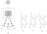
図13(a)は、図11に示す形成体(1)における、基材(2)に対する観察角度の変化を示す模式図であり、図13(b1)及び図13(b2)は、図13(a)において視認される第一の画像(3)を示す平面図及び拡大図である。
FIG. 13A is a schematic diagram showing a change in the observation angle with respect to the
図13(a)に示すように、第一の情報画線(4)が光輝性を有する画線として視認される領域(θ4)内において、基材(2)に対する観察角度を、第二1の観察角度(E21)から第二2の観察角度(E22)へと連続的に変化させて観察した場合、観察角度の変化に伴い、第一の情報画線(4)における光源(Q)からの入射光を反射する位置が始点側から終点側へと徐々に変化する。それにより、図13(b2)に点線で示す、第一の情報画線(4)の光輝性を有する箇所も、図13(b2)に示す矢印方向に連続的に動いているように視認される。 As shown in FIG. 13A, in the region (θ4) where the first information image line (4) is visually recognized as an image line having glitter, the observation angle relative to the substrate (2) is set to the second 1 viewing angle (E2 1) from when observed by continuously changing into the second second observation angle (E2 2), with a change in viewing angle, the light source of the first information image line (4) (Q The position where the incident light from) is reflected gradually changes from the start point side to the end point side. As a result, the portion having the glitter of the first information image line (4) shown by the dotted line in FIG. 13 (b2) is also visually recognized as moving continuously in the direction of the arrow shown in FIG. 13 (b2). The
例えば、観察角度を第二1の観察角度(E21)から第二2の観察角度(E22)へと連続的に変化させて観察した場合、第一の画像(3)は、右から左へと動いているように視認され、反対に、第二2の観察角度(E22)から第二1の観察角度(E21)へと連続的に変化させて観察した場合、第一の画像(3)は、左から右へと動いているように視認される。なお、第一の画像(3)の左右に動く最大幅(動き量)は、第一の情報画線(4)の光輝性を有する箇所の変化量と同一であることから、基準線(H1)の長さと同一の範囲内で、左右に動く。 For example, the left observation angle when viewed in a second one continuously changed and observed from an angle (E2 1) to the second second observation angle (E2 2), the first image (3), from the right It is visually recognized as moving into, on the contrary, when observing it from the second second observation angle (E2 2) is continuously changed to a second first viewing angle (E2 1), first image (3) is visually recognized as moving from left to right. Note that the maximum width (amount of movement) that moves to the left and right of the first image (3) is the same as the amount of change in the portion having the glitter of the first information image line (4), so the reference line (H1 ) Moves left and right within the same range as the length.
このように、本発明の第一の画像(3)は、立体的、かつ、連続的に動いているように視認することが可能となる。 Thus, the first image (3) of the present invention can be viewed as if it is moving three-dimensionally and continuously.
次に、第一の情報画線(4)における基準線が、前述した図3に示すように異なる方向で万線状に配置された形成体(1)の視認原理について説明する。異なる方向で万線状に配置された形成体(1)を、第一の観察角度(E1)から観察した場合、第一の情報画線(4)は、光輝性を有しない画線として視認される。よって、図11において前述した基準線を同じ方向で万線状に配置された形成体(1)と同様に、複数の第一の情報画線(4)から成る第一の画像(3)は、平面的な画像として視認される。 Next, the visual recognition principle of the formed body (1) in which the reference lines in the first information image line (4) are arranged in different lines in different directions as shown in FIG. 3 will be described. When the formed bodies (1) arranged in different directions in different directions are observed from the first observation angle (E1), the first information image line (4) is visually recognized as an image line having no glitter. Is done. Therefore, the first image (3) composed of a plurality of first information lines (4) is similar to the formed body (1) in which the reference lines described above in FIG. It is visually recognized as a planar image.
図14は、第一の情報画線(4)における基準線が、異なる方向で万線状に配置された形成体(1)を、第二の観察角度(E2)から観察した際の平面図である。基材(2)に対して第二の観察角度(E2)から観察した場合、第一の情報画線(4)は、光輝性を有する画線として視認される。 FIG. 14 is a plan view when the formed body (1) in which the reference lines in the first information image line (4) are arranged in different directions in different directions is observed from the second observation angle (E2). It is. When observed from the second observation angle (E2) with respect to the substrate (2), the first information image line (4) is visually recognized as an image line having glitter.
図14(a1)は、観察者の左目(L)に視認される第一Lの画像(3L)を示す平面図であり、図14(a2)は、図14(a1)の一部を拡大した図である。図14(a2)に示すように、第二の観察角度(E2)において観察者の左目(L)には、第一の情報画線(4)における点線部が光輝性を有して視認され、実線部は、光輝性を有しない画線として視認される。 FIG. 14 (a1) is a plan view showing a first L image (3L) visually recognized by the left eye (L) of the observer, and FIG. 14 (a2) is an enlarged view of a part of FIG. 14 (a1). FIG. As shown in FIG. 14 (a2), at the second observation angle (E2), the left eye (L) of the observer visually recognizes the dotted line portion in the first information image line (4) with glitter. The solid line portion is visually recognized as an image line having no glitter.
図12において前述した基準線を同じ方向として第一の情報画線(4)を配置した場合には、第一の情報画線(4)における光輝性を有して視認される部分が、複数の第一の情報画線(4)において同一箇所であるが、基準線を異なる方向として配置した場合には、図14(a2)に示すように、基準線の傾きに伴い、複数の第一の情報画線(4)において徐々に異なる位置となる。 In the case where the first information image line (4) is arranged with the reference line described above in FIG. 12 as the same direction, there are a plurality of portions visually recognized with glitter in the first information image line (4). In the first information image line (4), when the reference line is arranged in a different direction, as shown in FIG. In the information line (4), the position gradually changes.
例えば、図14においては、点線で示す光輝性を有して視認される部分が、徐々に図内右方向(X2)に変化している。よって、観察者の左目(L)には、図14(a2)に示す、複数の第一の情報画線(4)における、光輝性を有して視認される箇所から成る、第一Lの画像(3L)が視認される。前述のとおり、光輝性を有して視認される箇所は変化することから、第一Lの画像(3L)は第一の画像(3)が斜めに変形した画像として視認される。 For example, in FIG. 14, the part visually recognized with the glitter indicated by the dotted line gradually changes in the right direction (X2) in the figure. Therefore, in the left eye (L) of the observer, the first L of the first information image lines (4) shown in FIG. An image (3L) is visually recognized. As described above, since the location that is visually recognized with the glitter changes, the first L image (3L) is visually recognized as an image obtained by obliquely deforming the first image (3).
図14(b1)は、観察者の右目(R)に視認される第一Rの画像(3R)を示す平面図であり、図14(b2)は、図14(b1)の一部を拡大した図である。図14(b2)に示すように、第二の観察角度(E2)において観察者の右目(R)には、第一の情報画線(4)における点線部が光輝性を有して視認され、実線部は、光輝性を有しない画線として視認される。 FIG. 14 (b1) is a plan view showing the first R image (3R) visually recognized by the observer's right eye (R), and FIG. 14 (b2) is an enlarged view of part of FIG. 14 (b1). FIG. As shown in FIG. 14 (b2), at the second observation angle (E2), the dotted line portion of the first information image line (4) is visually recognized by the viewer's right eye (R) with glitter. The solid line portion is visually recognized as an image line having no glitter.
前述した左目(L)の視認状態と同様に、基準線を異なる方向として配置した場合には、図14(b2)に示すように、基準線の傾きに伴い、複数の第一の情報画線(4)において徐々に異なる位置となる。 Similar to the left eye (L) viewing state described above, when the reference line is arranged in a different direction, as shown in FIG. In (4), the position gradually changes.
よって、観察者の右目(R)には、図14(b2)に示す、複数の第一の情報画線(4)における、光輝性を有して視認される箇所から成る第一Rの画像(3R)が視認される。前述のとおり、光輝性を有して視認される箇所は変化することから、第一Lの画像(3L)は第一の画像(3)が斜めに変形した画像として視認される。 Therefore, in the right eye (R) of the observer, the first R image made up of the portions of the plurality of first information image lines (4) shown in FIG. (3R) is visually recognized. As described above, since the location that is visually recognized with the glitter changes, the first L image (3L) is visually recognized as an image obtained by obliquely deforming the first image (3).
図14(c1)は、観察者の両目(L、R)に視認される第一の画像(3)を示す平面図であり、図14(c2)は、図14(c1)の一部を拡大した図である。前述したように、第二の観察角度(E2)において観察者の左目(L)には、図14(a1)に示す第一Lの画像(3L)が視認され、右目(R)には、図14(b1)に示す第一Rの画像(3R)が視認される。 FIG. 14 (c1) is a plan view showing the first image (3) visually recognized by both eyes (L, R) of the observer, and FIG. 14 (c2) is a part of FIG. 14 (c1). FIG. As described above, the first L image (3L) shown in FIG. 14 (a1) is visually recognized in the left eye (L) of the observer at the second observation angle (E2), and the right eye (R) The first R image (3R) shown in FIG.
前述のとおり、左目(L)で視認される第一の情報画線(4)と、右目で視認される第一の情報画線(4)は、左右の視点を結ぶ線(G)に対して、位相差を持った画線として視認されることから、第一Rの画像(3R)と、第一Lの画像(3L)においても、基準線(H1)に対して位相差を持った画像として観察者の両目(L、R)にそれぞれ視認される。よって、右目で視認される第一の画像(3)と、左目で視認される第一の画像(3)の位相が異なることで、両眼視差により観察者には斜めに変形した色彩層の色彩から成る第一の画像(3)が、立体的な画像として視認される。 As described above, the first information line (4) visually recognized by the left eye (L) and the first information line (4) visually recognized by the right eye are relative to the line (G) connecting the left and right viewpoints. Therefore, the first R image (3R) and the first L image (3L) have a phase difference with respect to the reference line (H1). The image is visually recognized by both eyes (L, R) of the observer. Therefore, the phase of the first image (3) visually recognized by the right eye and the first image (3) visually recognized by the left eye is different from that of the color layer that is obliquely deformed by the binocular parallax. The first image (3) composed of colors is visually recognized as a stereoscopic image.
さらに、観察角度を変化させることで、その観察角度の変化に伴い、動的に第一の画像(3)を視認することが可能である。次に、第一の画像(3)が動的に視認される原理について説明する。 Furthermore, by changing the observation angle, the first image (3) can be visually recognized dynamically as the observation angle changes. Next, the principle by which the first image (3) is visually recognized will be described.
図15(a)は、図14に示す形成体(1)における、基材(2)に対する観察角度の変化を示す模式図であり、図15(b1)及び図15(b2)は、図15(a)において視認される第一の画像(3)を示す平面図及び拡大図である。 Fig.15 (a) is a schematic diagram which shows the change of the observation angle with respect to a base material (2) in the formation body (1) shown in FIG. 14, FIG.15 (b1) and FIG.15 (b2) are FIG. It is the top view and enlarged view which show the 1st image (3) visually recognized in (a).
前述のとおり、複数の異なる方向に配置した第一の情報画線(4)から成る第一の画像(3)においては、斜めに変形した画像として立体的に視認される。よって、図15(a)に示すように、第一の情報画線(4)が光輝性を有する画線として視認される領域(θ4)内において、基材(2)に対する観察角度を、第二1の観察角度(E21)から第二2の観察角度(E22)へと連続的に変化させて観察した場合、観察角度の変化に伴い、第一の情報画線(4)における光源(Q)からの入射光を反射する位置が始点側から終点側へと徐々に変化する。それにより、図15(b2)に点線で示す、第一の情報画線(4)の光輝性を有する箇所も、図15(b2)に示す矢印方向である斜め方向に連続的に動いているように視認される。 As described above, in the first image (3) composed of the first information lines (4) arranged in a plurality of different directions, the image is viewed stereoscopically as an obliquely deformed image. Therefore, as shown in FIG. 15A, in the region (θ4) where the first information image line (4) is visually recognized as a bright image line, the observation angle with respect to the base material (2) is set to two first viewing angle (E2 1) from when observed by continuously changing into the second second observation angle (E2 2), with a change in viewing angle, the light source of the first information image line (4) The position where the incident light from (Q) is reflected gradually changes from the start point side to the end point side. Accordingly, the portion having the glitter of the first information image line (4) indicated by the dotted line in FIG. 15 (b2) also continuously moves in the oblique direction that is the arrow direction shown in FIG. 15 (b2). As seen.
例えば、観察角度を第二1の観察角度(E21)から第二2の観察角度(E22)へと連続的に変化させて観察した場合、第一の画像(3)は、右斜め上から左斜め下へと動いているように視認され、反対に、第二2の観察角度(E22)から第二1の観察角度(E21)へと連続的に変化させて観察した場合、第一の画像(3)は、左斜め下から右斜め上へと動いているように視認される。なお、第一の画像(3)の左右斜め方向に動く最大幅(動き量)は、第一の情報画線(4)の光輝性を有する箇所の変化量と同一であることから、基準線(H1)の長さと同一の範囲内で、左右に動く。 For example, when observed by continuously changing the observation angle from the second first viewing angle (E2 1) to the second second observation angle (E2 2), the first image (3) is on the right diagonal If the visually recognized as moving to the left obliquely downward, the opposite was observed continuously changed from the second second observation angle (E2 2) to the second first viewing angle (E2 1), The first image (3) is visually recognized as moving from the lower left diagonal to the upper right diagonal. Note that the maximum width (movement amount) of the first image (3) that moves in the left-right diagonal direction is the same as the change amount of the portion having the glitter of the first information image line (4). It moves left and right within the same range as the length of (H1).
以上、立体視可能な第一の画像(3)は、構成する複数の第一の情報画線(4)を図2に示すように基準線(H1)を同じ方向とした場合には、観察角度の変化により左右に動的に視認され、図3に示すように基準線(H1)を異なる方向とした場合には、観察角度の変化により斜め方向に動的に視認される。 As described above, the stereoscopically viewable first image (3) is observed when the plurality of first information lines (4) constituting the reference line (H1) have the same direction as shown in FIG. When the reference line (H1) is set in a different direction as shown in FIG. 3, it is visually recognized in an oblique direction due to a change in the observation angle.
なお、異なる方向に配置した場合の画線形状については、前述した図3に示すように、徐々に円弧状の第一の情報画線(4)が左に傾いていく配置に限らず、第一の画像(3)を斜め方向に動的に視認可能であれば、図16に矢印として図示するように、徐々に右に傾いたのち、反対に、徐々に左に傾く構成とすることも可能である。 Note that the image line shape when arranged in different directions is not limited to the arrangement in which the first information image line (4) having an arc shape is gradually inclined to the left as shown in FIG. If one image (3) is dynamically visible in an oblique direction, it may be configured to gradually tilt to the right and then gradually to the left as shown by an arrow in FIG. Is possible.
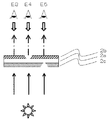
透過光下においては、図17に示すように、第一の色彩層(2a)が凹ではない観察点(E3)においては第一の色彩層(2b)と第二の色彩層(2c)が混色した色彩が観察され、第一の色彩層(2a)が凹となっている観察点(E4)においては第二の色彩層(2c)の色彩が観察されるため、第一の画像(3)が第二の色彩層(2c)の色彩で視認される。 Under transmitted light, as shown in FIG. 17, the first color layer (2b) and the second color layer (2c) are at the observation point (E3) where the first color layer (2a) is not concave. Since the mixed color is observed and the color of the second color layer (2c) is observed at the observation point (E4) where the first color layer (2a) is concave, the first image (3 ) Is visually recognized in the color of the second color layer (2c).
(第二の実施形態)
次に、前述した形成体(1)の変形例について説明する。図18は、領域(Z)内に配置された、変形例の形成体(1)を示す平面図である。なお、前述した実施の形態と同様の点については、以下説明を省略する。形成体(1)は、前述した実施の形態と同様に、立体視可能な画像を有している。変形例における立体視可能な画像は、前述した実施の形態よりも、動的効果が高い画像である。
(Second embodiment)
Next, a modified example of the above-described formed body (1) will be described. FIG. 18 is a plan view showing a modified forming body (1) arranged in the region (Z). The description of the same points as those of the above-described embodiment will be omitted below. The formed body (1) has a stereoscopically visible image as in the above-described embodiment. The stereoscopically viewable image in the modification is an image having a higher dynamic effect than the above-described embodiment.
図18に示すように、形成体(1)は、第一の画像(3)と、第二の画像(5)を有する。なお、第一の画像(3)は、前述した画像と同一の画像であることから、説明を省略する。図17に示すように、第二の画像(5)は、領域(Z)内に配置された第一の画像(3)に対して、近接又は隣接する位置に、形成されている。 As shown in FIG. 18, the formed body (1) has a first image (3) and a second image (5). Since the first image (3) is the same image as the above-described image, the description thereof is omitted. As shown in FIG. 17, the second image (5) is formed at a position close to or adjacent to the first image (3) arranged in the region (Z).
隣接する位置とは、第一の画像(3)及び第二の画像(5)が隣り合って接して形成されることであり、近接する位置とは、第一の画像(3)及び第二の画像(5)が基材(2)上において近い位置に形成されることである。なお、近接又は隣接する位置においては、観察者の視野や左右の目の間の距離、第一の画像(3)及び第二の画像(5)の大きさに合わせて、色彩層の色彩から成る第一の画像(3)及び第二の画像(5)がいずれも立体視可能となる距離(W)の範囲で適宜設定する。 The adjacent position is that the first image (3) and the second image (5) are formed adjacent to each other, and the adjacent positions are the first image (3) and the second image. The image (5) is formed at a close position on the substrate (2). It should be noted that, in the proximity or adjacent position, the color of the color layer is determined according to the visual field of the observer, the distance between the left and right eyes, and the size of the first image (3) and the second image (5). The first image (3) and the second image (5) are appropriately set within the range of the distance (W) at which stereoscopic viewing is possible.
第二の画像(5)は、少なくとも一つの第二の要素領域(5E)から成る。第二の要素領域(5E)は、第二の画像(5)を構成するパーツであり、第二の要素領域(5E)が配置されて、全体で第二の画像(5)である「N」の文字形状を形成している。なお、明確に説明するために、第二の要素領域(5E)を示す線を図示しているが、仮想の線であり、実際の第二の画像(5)には形成されない。 The second image (5) consists of at least one second element region (5E). The second element region (5E) is a part constituting the second image (5), and the second element region (5E) is arranged so that the second image region (5E) is “N” as a whole. "Is formed. For the sake of clarity, a line indicating the second element region (5E) is illustrated, but is a virtual line and is not formed in the actual second image (5).
なお、第二の画像(5)に対する第二の要素領域(5E)の分割方法については、前述した第一の画像(3)に対する第一の要素領域(3E)の分割方法と同様であることから、説明を省略する。 The method for dividing the second element region (5E) for the second image (5) is the same as the method for dividing the first element region (3E) for the first image (3) described above. Therefore, the description is omitted.
第二の画像(5)は、万線状の第二の情報画線(6)を有する。第二の情報画線(6)と前述した第一の画像(3)を形成する第一の情報画線(4)は、形状、形成する材料、配置するピッチは同一であるが、画線の向きが異なる。 The second image (5) has a second line-shaped information image line (6). The second information image line (6) and the first information image line (4) forming the first image (3) described above have the same shape, material to be formed, and pitch to be arranged, but the image line The direction of is different.
第二の画像(5)は、第一の画像(3)を形成する円弧状の第一の情報画線(4)と頂点(T)の向きが異なる向きで、第二の方向(X2)に配置されている。第二の情報画線(6)を配置する方向は、第二の要素領域(5E)内において同じ方向に万線状に配置されていればよく、第一の要素領域(3E)と同様に、複数の第二の要素領域(5E)が、互いに異なる方向に配置されていても良い。よって、第二の方向(X2)は、前述した第一の方向(X1)と同じ又は異なる方向とすることが可能である。 The second image (5) has a second direction (X2) in which the direction of the apex (T) is different from that of the arc-shaped first information image line (4) forming the first image (3). Is arranged. The second information image line (6) may be arranged in the same direction in the second element region (5E) in the same direction as in the first element region (3E). The plurality of second element regions (5E) may be arranged in different directions. Therefore, the second direction (X2) can be the same as or different from the first direction (X1) described above.
第一の情報画線(4)と第二の情報画線(6)の頂点(T)の向きは、1〜180度の範囲内で異なる事が可能であるが、略180度であることが、好ましい。 The direction of the vertex (T) of the first information line (4) and the second information line (6) can be different within a range of 1 to 180 degrees, but is approximately 180 degrees. Is preferred.
略180度とすることで、第一の画像(3)及び第二の画像(5)を立体的、かつ、動的に視認する際に、より動的効果が高く、色彩層の色彩から成る画像として視認される。なお、動的効果に視認される原理についての詳細は後述する。 When the first image (3) and the second image (5) are viewed three-dimensionally and dynamically, the dynamic effect is higher and the color layer is composed of colors of the color layer. Visible as an image. In addition, the detail about the principle visually recognized by a dynamic effect is mentioned later.
以下、本実施の形態の変形例においては、第一の情報画線(4)と第二の情報画線(6)の頂点の向きが180度異なるとして説明する。 Hereinafter, in the modified example of the present embodiment, it is assumed that the vertex directions of the first information image line (4) and the second information image line (6) are different by 180 degrees.
図19は、第二の観察角度(E2)における、第二の画像(5)を形成する第二の情報画線(6)の視認原理の詳細を示す模式図である。図19(a)に示すように、第二の観察角度(E2)において、第二の情報画線(6)は、光輝性を有して視認される。 FIG. 19 is a schematic diagram showing details of the visual recognition principle of the second information image line (6) forming the second image (5) at the second observation angle (E2). As shown in FIG. 19A, at the second observation angle (E2), the second information image line (6) is visually recognized with glitter.
前述のとおり、本発明の第二の情報画線(6)は、前述した第一の情報画線(4)と同様に、基材(2)に対して凹形状の円弧状画線であることから、光源(Q)からの反射光(V1、V2、V3、V4、V5)は、一方向ではなく、他方向に反射する。 As described above, the second information image line (6) of the present invention is a concave arc-shaped image line with respect to the base material (2), similarly to the first information image line (4) described above. Therefore, the reflected light (V1, V2, V3, V4, V5) from the light source (Q) is reflected not in one direction but in the other direction.
観察者の左目(L)の視野角度はθLであることから、左目(L)には、反射光(V4、V5)が視認される。一方、反射光(V1、V2、V3)は、視野角度θLの範囲外であることから、視認されない。よって、第二の情報画線(6)は、観察者の左目(L)には、図19(b1)に示すように、終点(D)側の点線部は光輝性を有して視認されるが、始点(U)側の実線部は光輝性を有しない画線として視認される。 Since the viewing angle of the left eye (L) of the observer is θL, the reflected light (V4, V5) is visually recognized by the left eye (L). On the other hand, the reflected light (V1, V2, V3) is not visually recognized because it is outside the range of the viewing angle θL. Therefore, the second information image line (6) is visually recognized by the left eye (L) of the observer as shown in FIG. 19 (b1) with the dotted line portion on the end point (D) side having glitter. However, the solid line portion on the start point (U) side is visually recognized as an image line having no glitter.
一方、観察者の右目(R)の視野角度はθRであることから、右目(R)には、反射光(V1、V2)が視認される。一方、反射光(V3、V4、V5)は、視野角度θRの範囲外であることから、視認されない。よって、第二の情報画線(6)は、観察者の右目(R)には、図19(c1)に示すように、始点(U)側の点線部は光輝性を有して視認されるが、終点(D)側の実線部は光輝性を有しない画線として視認される。 On the other hand, since the viewing angle of the observer's right eye (R) is θR, reflected light (V1, V2) is visually recognized by the right eye (R). On the other hand, the reflected light (V3, V4, V5) is not visually recognized because it is outside the range of the viewing angle θR. Therefore, the second information image line (6) is visually recognized by the observer's right eye (R) with the dotted line portion on the start point (U) side having glitter as shown in FIG. 19 (c1). However, the solid line portion on the end point (D) side is visually recognized as an image line having no glitter.
図19(b1)に示す左目(L)で視認される第二の情報画線(6)の光輝性を有して視認される箇所と、図19(c1)に示す右目で視認される第二の情報画線(6)の光輝性を有して視認される箇所は、始点(U)と終点(D)を結ぶ直線である基準線(H1)に対して、位相差を持った画線として視認される。よって、両眼視差により、観察者には図19(d1)に示すように、第二の情報画線(6)は立体画線として視認される。 A portion visually recognized by the second information image line (6) visually recognized by the left eye (L) shown in FIG. 19 (b1) and a first eye visually recognized by the right eye shown in FIG. 19 (c1). The portion visually recognized with the brightness of the second information image line (6) is an image having a phase difference with respect to the reference line (H1) which is a straight line connecting the start point (U) and the end point (D). Visible as a line. Accordingly, due to the binocular parallax, the second information image line (6) is visually recognized by the observer as a three-dimensional image line as shown in FIG. 19 (d1).
図19(b2)、図19(c2)及び図19(d2)は、図16に示した変形例の第一の画像(3)を形成する第一の情報画線(4)を第二の観察角度(E2)から視認した際の模式図である。図19(b2)は、観察者の左目(L)で視認される第一の情報画線(4)であり、図19(c2)は、観察者の右目(R)で視認される第一の情報画線(4)であり、図19(d2)は、観察者の左右の目(L、R)で視認される第一の情報画線(4)である。 19 (b2), FIG. 19 (c2) and FIG. 19 (d2) show the first information line (4) forming the first image (3) of the modification shown in FIG. It is a schematic diagram at the time of visually recognizing from an observation angle (E2). FIG. 19 (b2) is the first information line (4) visually recognized by the left eye (L) of the observer, and FIG. 19 (c2) is the first information visually recognized by the observer's right eye (R). FIG. 19D2 shows the first information image line (4) visually recognized by the left and right eyes (L, R) of the observer.
第二の画像(5)を形成する第二の情報画線(6)は、前述した第一の画像(3)を形成する第一の情報画線(4)と略180度異なる方向に配列されている。よって、第二の観察角度(E2)においては、観察者に視認される各情報画線(4、6)の点線部に示す光輝性を有して視認される箇所が、観察者の左右の目(L、R)で逆の部分が視認される。 The second information line (6) that forms the second image (5) is arranged in a direction that is approximately 180 degrees different from the first information line (4) that forms the first image (3) described above. Has been. Therefore, at the second observation angle (E2), the portions that are visually recognized with the glitter indicated by the dotted line portions of the information image lines (4, 6) visually recognized by the observer are left and right of the observer. The opposite part is visually recognized by the eyes (L, R).
例えば、図19(b1)及び図19(b2)は、それぞれ観察者の左目(L)で視認される各情報画線(4、6)であるが、図19(b1)においては、第二の情報画線(6)の終点(D)側が光輝性を有して視認される。一方、図19(b2)においては、第一の情報画線(4)の始点(U)側が光輝性を有して視認される。 For example, FIG. 19 (b1) and FIG. 19 (b2) are information lines (4, 6) visually recognized by the left eye (L) of the observer, respectively, but in FIG. The end point (D) of the information image line (6) is visually recognized with glitter. On the other hand, in FIG. 19 (b2), the start point (U) side of the first information image line (4) is visually recognized with glitter.
第一の画像(3)と第二の画像(5)を形成する各情報画線(4、6)が、観察者の左右の目(L、R)で逆の部分が光輝性しているように視認されることで、基材(2)を傾けて視認した際、第一の画像(3)と第二の画像(5)は、異なる方向に動的に視認される。なお、異なる方向に動的に視認される原理の詳細は後述する。 In the information image lines (4, 6) forming the first image (3) and the second image (5), the opposite parts of the left and right eyes (L, R) of the observer are brilliant. Thus, when the substrate (2) is tilted and visually recognized, the first image (3) and the second image (5) are dynamically visually recognized in different directions. The details of the principle of dynamically visually recognizing in different directions will be described later.
図20は、第二の画像(5)を、前述した第二の観察角度(E2)から観察した際の平面図である。図20(a1)は、観察者の左目(L)に視認される第二Lの画像(5L)を示す平面図であり、図20(a2)は、図20(a1)の一部を拡大した図である。図20(a2)に示すように、第二の観察角度(E2)において観察者の左目(L)には、第二の情報画線(6)における点線部が光輝性を有して視認される。一方、図20(a2)における実線部は、光輝性を有しない画線として視認される。よって、点線部が光輝性を有し、かつ、実線部が光輝性を有さない、複数の第二の情報画線(6)から成る第二Lの画像(5L)が視認される。 FIG. 20 is a plan view when the second image (5) is observed from the second observation angle (E2) described above. FIG. 20 (a1) is a plan view showing a second L image (5L) visually recognized by the left eye (L) of the observer, and FIG. 20 (a2) is an enlarged view of a part of FIG. 20 (a1). FIG. As shown in FIG. 20 (a2), at the second observation angle (E2), the dotted line portion in the second information image line (6) is visually recognized by the left eye (L) of the viewer. The On the other hand, the solid line portion in FIG. 20 (a2) is visually recognized as an image line having no glitter. Therefore, the second L image (5L) composed of a plurality of second information image lines (6) in which the dotted line portion has glitter and the solid line portion does not have glitter is visually recognized.
図20(b1)は、観察者の右目(R)に視認される第二Rの画像(5R)を示す平面図であり、図20(b2)は、図20(b1)の一部を拡大した図である。図20(b2)に示すように、第二の観察角度(E2)において観察者の右目(R)には、第二の情報画線(6)における点線部が光輝性を有して視認される。一方、図20(b2)における実線部は、光輝性を有しない画線として視認される。よって、点線部が光輝性を有し、かつ、実線部が光輝性を有さない複数の第二の情報画線(6)から成る第二Rの画像(5R)が視認される。 FIG. 20 (b1) is a plan view showing a second R image (5R) visually recognized by the observer's right eye (R), and FIG. 20 (b2) is an enlarged view of a part of FIG. 20 (b1). FIG. As shown in FIG. 20 (b2), at the second observation angle (E2), the dotted line portion of the second information image line (6) is visually recognized by the viewer's right eye (R) with glitter. The On the other hand, the solid line portion in FIG. 20B2 is visually recognized as an image line having no glitter. Therefore, the second R image (5R) composed of a plurality of second information image lines (6) in which the dotted line portion has glitter and the solid line portion does not have glitter is visually recognized.
図20(c1)は、観察者の両目(L、R)に視認される第二の画像(5)を示す平面図であり、図20(c2)は、図20(c1)の一部を拡大した図である。前述したように、第二の観察角度(E2)において観察者の左目(L)には、図20(a1)に示す第二Lの画像(5L)が視認され、右目(R)には、図20(b1)に示す第二Rの画像(5R)が視認される。 FIG. 20 (c1) is a plan view showing a second image (5) visually recognized by both eyes (L, R) of the observer, and FIG. 20 (c2) shows a part of FIG. 20 (c1). FIG. As described above, the second L image (5L) shown in FIG. 20 (a1) is visually recognized in the left eye (L) of the observer at the second observation angle (E2), and the right eye (R) A second R image (5R) shown in FIG.
前述のとおり、左目(L)で視認される第二の情報画線(6)と、右目で視認される第二の情報画線(6)は、始点(U)と終点(D)を結ぶ直線である基準線(H1)に対して、位相差を持った画線として視認される。よって、複数の情報画線(4)から成る第二の画像(5)は、第二Rの画像(5R)と、第二Lの画像(5L)は、基準線(H1)に対して位相差を持った画像として観察者の両目(L、R)にそれぞれ視認されることから、右目で視認される第二の画像(5)と、左目で視認される第二の画像(5)の位相が異なることで、両眼視差により観察者には、図20(c1)に示すように、第二の画像(5)は立体的な画像として視認される。 As described above, the second information image line (6) visually recognized by the left eye (L) and the second information image line (6) visually recognized by the right eye connect the start point (U) and the end point (D). It is visually recognized as an image line having a phase difference with respect to the reference line (H1) which is a straight line. Therefore, the second image (5) composed of a plurality of information lines (4) is the second R image (5R) and the second L image (5L) is positioned relative to the reference line (H1). Since it is visually recognized by both eyes (L, R) of the observer as images having a phase difference, the second image (5) visually recognized by the right eye and the second image (5) visually recognized by the left eye. Due to the different phases, the second image (5) is visually recognized as a stereoscopic image by the observer due to the binocular parallax, as shown in FIG. 20 (c1).
図21(a)は、基材(2)に対する観察角度の連続的な変化を示す模式図であり、図21(b)は、第二の観察角度(E2)から視認される各画像(3、5)の平面図である。図21(a)に示す、各情報画線(4、6)が光輝性を有する画線として視認される領域(θ4)内において第二の観察角度(E2)から観察した場合、図21(b)に示すように、第一の画像(3)及び第二の画像(5)は立体的に視認される。 FIG. 21A is a schematic diagram showing a continuous change in the observation angle with respect to the substrate (2), and FIG. 21B shows each image (3) viewed from the second observation angle (E2). 5) is a plan view. When the information lines (4, 6) shown in FIG. 21A are observed from the second observation angle (E2) in the region (θ4) where the information lines (4, 6) are visually recognized as bright lines, FIG. As shown in b), the first image (3) and the second image (5) are viewed three-dimensionally.
図21(c)は、第二1の観察角度(E21)から視認される各画像(3、5)の平面図である。領域(θ4)内において、観察角度を第二の観察角度(E2)から第二1の観察角度(E21)へ連続的に変化させて観察した場合、基材(2)に対する観察角度の変化に伴い、情報画線(4)における光源(Q)からの入射光を反射する位置が徐々に変化する。 FIG. 21 (c) is a plan view of each image (3, 5) which is visible from the second first viewing angle (E2 1). In the region (.theta.4), a change in viewing angle for the case where the observation angle was second continuously observed by changing the observation angle from (E2) to the second first viewing angle (E2 1), the substrate (2) Accordingly, the position where the incident light from the light source (Q) in the information image line (4) is reflected gradually changes.
前述のとおり、第一の画像(3)を形成する第一の情報画線(4)と、第二の画像(5)を形成する第二の情報画線(6)は、略180度異なる方向に配列されている。それにより、第二の観察角度(E2)における各情報画線(4、6)の光輝性を有して視認される箇所は、観察者の左右の目(L、R)で逆の部分が光輝性を有しているように視認される。 As described above, the first information line (4) that forms the first image (3) and the second information line (6) that forms the second image (5) differ by approximately 180 degrees. Arranged in the direction. Thereby, the part visually recognized with the brightness of each information image line (4, 6) at the second observation angle (E2) is the opposite part of the left and right eyes (L, R) of the observer. It is visually recognized as having glitter.
例えば、第二の観察角度(E2)から第二1の観察角度(E21)へと連続的に変化させて観察した場合、第一の画像(3)を形成する第一の情報画線(4)は、始点側から終点側へ光輝性を有して視認される箇所が変化する。それにより、立体的に視認される第一の画像(3)は、図21(c)に示す破線(F)を基準とした場合、破線(F)から右へ動いているように視認される。 For example, the second viewing angle when viewed by continuously changing from (E2) to the second first viewing angle (E2 1), the first information image lines forming a first image (3) ( In 4), the portion that is visually recognized with glitter is changed from the start point side to the end point side. Thereby, the first image (3) visually recognized in three dimensions is visually recognized as moving to the right from the broken line (F) when the broken line (F) shown in FIG. 21 (c) is used as a reference. .
一方、第二の画像(5)を形成する第二の情報画線(6)は、終点側から始点側へ光輝性を有して視認される箇所が変化する。それにより、立体的に視認される第二の画像(5)は、第二の情報画線(6)が第一の情報画線(4)に対し、逆の部分が光輝性していることから、破線(F)から左へ動いているように視認される。 On the other hand, in the second information image line (6) that forms the second image (5), the visible portion changes from the end point side to the start point side with glitter. Thereby, in the second image (5) visually recognized in three dimensions, the second information image line (6) is brilliant in the opposite part to the first information image line (4). From the broken line (F), it is visually recognized as moving to the left.
図21(d)は、第二2の観察角度(E22)から視認される各画像(3、5)の平面図である。第二の観察角度(E2)から第二2の観察角度(E22)へと連続的に変化させて観察した場合、第二の観察角度(E2)から第二1の観察角度(E21)へと連続的に変化させた場合とは逆に、第一の画像(3)は、破線(F)から左へ動いているように視認される。一方、第二の画像(5)は、破線(F)から右へ動いているように視認される。 FIG. 21 (d) is a plan view of each image (3, 5) which is visible from the second second observation angle (E2 2). When viewed in a second continuously changed and observed from an angle (E2) to the second second observation angle (E2 2), the second first viewing angle from the second observation angle (E2) (E2 1) Contrary to the case where it is continuously changed, the first image (3) is visually recognized as moving to the left from the broken line (F). On the other hand, the second image (5) is visually recognized as moving to the right from the broken line (F).
前述のとおり、各画像(3、5)の左右に動く最大幅(動き量)は、各情報画線(4、6)の光輝性を有する箇所の変化量と同一であることから、基準線(H1)の長さと同一の範囲内で、左右に動く。 As described above, the maximum width (amount of movement) that moves to the left and right of each image (3, 5) is the same as the amount of change in the portion having the glitter of each information image line (4, 6). It moves left and right within the same range as the length of (H1).
例えば、基準線(H1)を5mmとし、第一の画像(3)のみを形成した際に、第二の観察角度(E2)から第二1の観察角度(E21)へ連続的に変化させて観察した場合、第一の画像(3)は、破線(F)から右へ略5mm動いているように視認される。また、第二の観察角度(E2)から第二2の観察角度(E22)へ連続的に変化させて観察した場合、第一の画像(3)は、破線(F)から左へ略5mm動いているように視認される。 For example, the reference line (H1) and 5 mm, when forming only the first image (3), continuously changed from a second viewing angle (E2) to the second first viewing angle (E2 1) The first image (3) is visually recognized as moving approximately 5 mm to the right from the broken line (F). Also, when viewed from the second observation angle (E2) is changed continuously to a second second observation angle (E2 2), the first image (3) is approximately 5mm from the dashed line (F) to the left Visible as if moving.
一方、第一の画像(3)及び第二の画像(5)を形成し、図21(c)に示すように、第二の観察角度(E2)から第二1の観察角度(E21)へ連続的に変化させて観察した場合、第一の画像(3)は、破線(F)から右へと略5mm動いているように視認される。一方、第二の画像(5)は、破線(F)から左へと略5mm動いているように視認される。よって、観察者には、第一の画像(3)及び第二の画像(5)が略10mm離れたように視認される。 On the other hand, the first image (3) and a second image (5) is formed, as shown in FIG. 21 (c), the second first viewing angle from the second observation angle (E2) (E2 1) When the image is observed while being continuously changed, the first image (3) is visually recognized as moving approximately 5 mm from the broken line (F) to the right. On the other hand, the second image (5) is visually recognized as moving approximately 5 mm from the broken line (F) to the left. Therefore, the viewer visually recognizes the first image (3) and the second image (5) as being approximately 10 mm apart.
また、図21(d)に示すように、第二の観察角度(E2)から第二2の観察角度(E22)へ連続的に変化させて観察した場合、第一の画像(3)は、破線(F)から左へと略5mm動いているように視認される。一方、第二の画像(5)は、破線(F)から右へと略5mm動いているように視認される。よって、観察者には、第一の画像(3)及び第二の画像(5)が略10mm、図21(c)とは逆方向に離れたように視認される。 Further, as shown in FIG. 21 (d), when viewed from the second observation angle (E2) is changed continuously to a second second observation angle (E2 2), the first image (3) is It is visually recognized as moving approximately 5 mm to the left from the broken line (F). On the other hand, the second image (5) is visually recognized as moving approximately 5 mm from the broken line (F) to the right. Therefore, the viewer visually recognizes the first image (3) and the second image (5) as approximately 10 mm apart from each other in the direction opposite to that in FIG.
このように、第一の画像(3)及び第二の画像(5)を形成する各情報画線(4、6)の頂点の向きを異なる方向とすることで、第一の画像(3)及び第二の画像(5)は異なる方向に動的に視認される。よって、前述した一つの画像を形成した場合と比べて、動的効果が高い形成体(1)となる。 Thus, the first image (3) is formed by setting the directions of the vertices of the information image lines (4, 6) forming the first image (3) and the second image (5) in different directions. And the second image (5) is dynamically viewed in different directions. Therefore, compared with the case where one image mentioned above is formed, it becomes a formation body (1) with a high dynamic effect.
なお、第一の画像(3)及び第二の画像(5)は、「N」という文字形状の同一の画像としていたが、図22に示すように、異なる画像とすることも可能である。また、第一の画像(3)を構成する第一の情報画線(4)と、第二の画像(5)を構成する第二の情報画線(4)の形状は円弧状であれば、図22に示すように、それぞれ異なる形状とすることが可能である。 Although the first image (3) and the second image (5) are the same image having the character shape “N”, they may be different images as shown in FIG. Moreover, if the shape of the 1st information image line (4) which comprises the 1st image (3), and the 2nd information image line (4) which comprises the 2nd image (5) are circular arc shape, As shown in FIG. 22, the shapes can be different from each other.
(第三の実施形態)
図23に第一の色彩層と第二の色彩層に凹形状の画線を構成した断面図を示す。(E3)は、表裏とも凹形状がないため、第一の色彩層と第二の色彩層の混色が観察できる。(E4)は第一の色彩層に凹形状の画線が構成されており、第二の色彩層の色が観察できる。(E5)は第二の色彩層に凹形状の画線が構成されており、第一の色彩層の色が観察できる。表裏同一箇所に凹形状の画線を構成することも可能であるが、この場合は表裏の情報画像が重なるため視認性が著しく劣る。
(Third embodiment)
FIG. 23 shows a cross-sectional view in which concave image lines are formed in the first color layer and the second color layer. Since (E3) does not have a concave shape on either side, the color mixture of the first color layer and the second color layer can be observed. In (E4), a concave image line is formed in the first color layer, and the color of the second color layer can be observed. In (E5), a concave image line is formed in the second color layer, and the color of the first color layer can be observed. Although it is possible to construct concave image lines on the same front and back, in this case, the information images on the front and back overlap, so the visibility is significantly inferior.
本発明の立体表示形成体は、カードの一部に形成したり、カードに立体表示形成体自体を貼付することができる。 The three-dimensional display formed body of the present invention can be formed on a part of a card, or the three-dimensional display formed body itself can be attached to the card.
以下、前述の発明を実施するための形態にしたがって、具体的に作製した立体視可能な印刷物の実施例について詳細に説明するが、本発明は、この実施例に限定されるものではない。 Hereinafter, an example of a three-dimensionally printed material that is specifically produced will be described in detail according to the mode for carrying out the invention described above, but the present invention is not limited to this example.
実施例として図16に示した形成体(1)を作製した。基材(2)の透明基体(2a)は、100μmの無色透明なPET−Gを使用した。第一の色彩層(2b)と第二の色彩層(2c)は、100μmの無色透明なPET−Gに樹脂用染料SDN(大阪化成品株式会社製)を使用し、第一の色彩層(2b)は、黄色に着色し、第二の色彩層(2c)は、紫色に着色した。着色後、第一の色彩層(2b)と第二の色彩層(2c)間に透明基体(2a)を挟み、100℃以上に加熱し、加圧して基材(2)を作製した。 As an example, a formed body (1) shown in FIG. 16 was produced. As the transparent substrate (2a) of the substrate (2), 100 μm colorless and transparent PET-G was used. For the first color layer (2b) and the second color layer (2c), a resin dye SDN (manufactured by Osaka Chemicals Co., Ltd.) is used for 100-μm colorless and transparent PET-G, and the first color layer ( 2b) was colored yellow and the second color layer (2c) was colored purple. After coloring, the transparent substrate (2a) was sandwiched between the first color layer (2b) and the second color layer (2c), heated to 100 ° C. or higher, and pressurized to produce a substrate (2).
第一の画像(3)の作製は、図24に示すように、第一の画像(3)の加工デザインの基となる立体モデル(K1)を作成した。このとき、立体モデル(K1)は、表面だけのデータにした。次に、図25に示すように、立体モデル(K1)を平行な線で輪切りにした立体モデル(K2)に修正した。図26に示すように、輪切りの立体モデル(K2)の投影モデル(K3)を作成する際、立体モデル(K1)では表面から見えない部分は、立体視に影響しないため、陰線処理により削除した。こうすることで、立体視で観察可能な画像が立体モデル(K1)とほぼ同等となる。 For the production of the first image (3), as shown in FIG. 24, a three-dimensional model (K1) serving as a basis for the processing design of the first image (3) was created. At this time, the three-dimensional model (K1) was data only on the surface. Next, as shown in FIG. 25, the three-dimensional model (K1) was corrected to a three-dimensional model (K2) obtained by cutting the solid model with parallel lines. As shown in FIG. 26, when creating the projection model (K3) of the three-dimensional model (K2) of the round slice, the portion that is not visible from the surface in the three-dimensional model (K1) is deleted by hidden line processing because it does not affect the stereoscopic vision. . By doing so, an image that can be observed stereoscopically becomes almost equivalent to the stereoscopic model (K1).
第一の情報画線(4)は、左右対称の円弧状画線とし、第1のピッチ(P1)100μmで複数形成した。第1の情報画線(4)の画線幅は、100μmとした。 The first information image line (4) was a symmetrical arc-shaped image line, and a plurality of the first information image lines (4) were formed at a first pitch (P1) of 100 μm. The line width of the first information line (4) was 100 μm.
始点(U)において、基準線(H1)に対する第1の情報画線(4)の接線(H2)が成す角度(θ1)と、第2の情報画線(6)の接線(H2)が成す角度(θ1)は、いずれも90度となった。また、終点(D)において、基準線(H1)に対する第1の情報画線(4)の接線(H3)が成す角度(θ2)は、陰線処理を行った部分を除き90度となった。陰線処理を行った部分は、陰線処理により自動的に角度(θ2)が定まった。 At the start point (U), an angle (θ1) formed by the tangent line (H2) of the first information line (4) with respect to the reference line (H1) and a tangent line (H2) of the second information line (6) are formed. The angles (θ1) were all 90 degrees. In addition, at the end point (D), the angle (θ2) formed by the tangent line (H3) of the first information image line (4) with respect to the reference line (H1) was 90 degrees except for the portion where the hidden line processing was performed. The angle (θ2) of the portion subjected to the hidden line process was automatically determined by the hidden line process.
第1の情報画線(4)及び第2の情報画線(6)は、レーザマーカ(キーエンス社製 MD−V9600)により、基材(2)上にレーザ加工することで、「N」形状の第1の画像(3)を形成した。なお、第1の情報画線(4)及び第2の情報画線(6)をレーザ加工する際には、各情報画線(4、6)の画像データを、公知の画像処理装置を用いて作製した後、その画像データをレーザマーカに入力し、基材(2)に対して加工を行った。 The first information image line (4) and the second information image line (6) are formed on the base material (2) with a laser marker (MD-V9600 manufactured by Keyence Corporation). A first image (3) was formed. When the first information image line (4) and the second information image line (6) are laser processed, the image data of each information image line (4, 6) is used using a known image processing apparatus. After that, the image data was input to the laser marker, and the substrate (2) was processed.
図27(a)に示すように、実施例にて作製した形成体(1)を、第1の観察角度(E1)から観察したところ、第1の情報画線(4)は光輝性を有しない画線として視認できた。よって、複数の第1の情報画線(4)で形成した第1の画像(3)は、いずれも平面的な画像として視認できた。 As shown in FIG. 27A, when the formed body (1) produced in the example was observed from the first observation angle (E1), the first information image line (4) had glitter. It was visible as an undrawn line. Therefore, all of the first images (3) formed by the plurality of first information lines (4) were visually recognized as planar images.
次に、図27(b)に示すように、形成体(1)を、第2の観察角度(E2)から観察したところ、第1の情報画線(4)は、光輝性を有する画線として視認できた。左目(L)で視認できる第1の情報画線(4)と、右目で視認できる第1の情報画線(4)は、始点(U)と終点(D)を結ぶ直線である基準線(H1)に対して、位相差を持った画線として視認できることから、第2の観察角度(E2)においては、両眼視差により第一の色彩層(2b)色彩である黄色の色彩の第1の画像(3)が、立体的な画像として視認できた。 Next, as shown in FIG. 27B, when the formed body (1) is observed from the second observation angle (E2), the first information image line (4) is an image line having glitter. As visible. The first information line (4) visible with the left eye (L) and the first information line (4) visible with the right eye are a reference line (a straight line connecting the start point (U) and the end point (D)). H1) can be visually recognized as an image line having a phase difference. Therefore, at the second observation angle (E2), the first color of the yellow color which is the first color layer (2b) color due to binocular parallax. The image (3) was visually recognized as a three-dimensional image.
さらに、透過光下においては、図28に示すとおり第一の色彩層(2b)の色彩である黄色地に、第二の色彩層(2c)の色彩である紫色の「N」形状の画像(3)が視認できた。 Furthermore, under transmitted light, a purple “N” -shaped image (color of the second color layer (2c) is displayed on the yellow background (color of the first color layer (2b)) as shown in FIG. 3) was visible.
1 立体表示形成体
2 基材
3 第1の画像
3E 第1の要素領域
3L 第1Lの画像
3R 第1Rの画像
4 第1の情報画線
Z 形成領域
P1 第1のピッチ
X1 第1の方向
X2 第2の方向
U 始点
T 頂点
D 終点
H1 基準線
H2 立ち上がり線
H3 立ち下がり線
E1 第1の観察角度
E2 第2の観察角度
E21 第21の観察角度
E22 第22の観察角度
K1 第一の画像(3)立体モデル
K2 立体モデル(K1)を平行な線で輪切りにした立体モデル
K3 立体モデル(K2)の投影モデル
DESCRIPTION OF
Claims (3)
前記第一の色彩層又は前記第二の色彩層の少なくとも一部に立体視可能な第一の画像が形成され、
前記第一の画像は、前記第一の画像を構成する少なくとも一つの第一の要素領域から成り、
前記第一の要素領域は、万線状に配置された、始点、頂点及び終点を有する円弧状の第一の情報画線から成り、
前記円弧状の第一の情報画線は、前記第一の画像を形成する前記色彩層を完全に除去及び前記透明基体の一部を除去して成る凹形状、かつ、前記明暗フリップフロップ性を有する画線であり、
前記基材を、定位置の光源に対して所定の角度から異なる角度へと、連続的に変化させて観察した場合、光源からの入射光を反射する位置が、円弧状の前記第一の情報画線上で徐々に移動することで、右目で視認される前記第一の画像と、左目で視認される前記第一の画像の位相が異なることで、両眼視差により前記第一の情報画線が形成された前記色彩層の色彩から成る前記第一の画像が立体的、かつ、動的に視認され、
透過光下においては、前記第一の情報画線が形成された前記色彩層と異なる前記色彩層の色彩から成る前記第一の画像が視認されることを特徴とする立体表示形成体。 A first color layer having a predetermined transmittance laminated on one surface of a transparent substrate having light and dark flip-flop properties, a color different from the first color layer, and a transmission that is the same as or different from the predetermined transmittance A substrate having a second color layer having a rate laminated on the other surface;
A first image that can be stereoscopically viewed is formed on at least a part of the first color layer or the second color layer,
The first image is composed of at least one first element region constituting the first image,
The first element region is composed of a circular arc-shaped first information image line having a start point, a vertex, and an end point, arranged in a line.
The arc-shaped first information image line has a concave shape formed by completely removing the color layer forming the first image and removing a part of the transparent substrate, and has the light and dark flip-flop properties. It is a line with
When the base material is observed while being continuously changed from a predetermined angle to a different angle with respect to the light source at a fixed position, the position where the incident light from the light source is reflected is the arc-shaped first information. By gradually moving on the image line, the phase of the first image visually recognized by the right eye and the phase of the first image visually recognized by the left eye are different, so that the first information image line is generated by binocular parallax. The first image consisting of the colors of the color layer formed with the three-dimensionally and dynamically viewed,
The three-dimensional display forming body, characterized in that, under transmitted light, the first image composed of colors of the color layer different from the color layer on which the first information image line is formed is visually recognized.
前記第二の画像は、前記第二の画像を構成する少なくとも一つの第二の要素領域から成り、
前記第二の要素領域は、前記第一の情報画線と同じ方向に万線状に配置された、始点、頂点及び終点を有する円弧状の第二の情報画線から成り、
円弧状の前記第二の情報画線は、前記第二の情報画像を形成する前記色彩層及び前記透明基体の一部を除去して成る凹形状、かつ、前記明暗フリップフロップ性を有する画線であり、前記第一の画像を形成する前記第一の情報画線と頂点の向きが異なる方向に配置され、
前記基材を、所定の角度から光源に対して異なる角度へと、連続的に変化させて観察した場合、前記第一の情報画線と前記第二の情報画線の頂点の向きが異なることで、右目で視認される前記第一の画像及び前記第二の画像と、左目で視認される前記第一の画像及び前記第二の画像の位相が異なることで、両眼視差により前記各情報画線が形成された前記色彩層の色彩から成る前記第一の画像及び前記第二の画像が立体的、かつ、異なる方向に動的に視認され、
透過光下においては、前記第一の情報画線及び前記第二の情報画線が形成された前記色彩層と異なる前記色彩層の色彩から成る前記第一の画像及び前記第二の画像が視認されることを特徴とする請求項1記載の立体表示形成体。 A second image that is stereoscopically visible is formed at a position close to or adjacent to the first image,
The second image is composed of at least one second element region constituting the second image,
The second element region is composed of an arc-shaped second information image line having a start point, a vertex, and an end point arranged in a line in the same direction as the first information image line,
The arc-shaped second information image line has a concave shape formed by removing a part of the color layer and the transparent substrate forming the second information image, and has the light and dark flip-flop property. And the first information image line forming the first image and the direction of the apex are arranged in different directions,
When the base material is continuously changed from a predetermined angle to a different angle with respect to the light source, the first information image line and the second information image line have different vertex directions. The phase difference between the first image and the second image visually recognized by the right eye and the phase of the first image and second image visually recognized by the left eye allows the information to be determined by binocular parallax. The first image and the second image composed of colors of the color layer on which an image line is formed are stereoscopically viewed dynamically in different directions,
Under the transmitted light, the first image and the second image that are different from the color layer on which the first information image line and the second information image line are formed are visually recognized. The three-dimensional display formation body according to claim 1, wherein the three-dimensional display formation body is formed.
Priority Applications (1)
| Application Number | Priority Date | Filing Date | Title |
|---|---|---|---|
| JP2013243607A JP6167351B2 (en) | 2013-11-26 | 2013-11-26 | 3D display formation |
Applications Claiming Priority (1)
| Application Number | Priority Date | Filing Date | Title |
|---|---|---|---|
| JP2013243607A JP6167351B2 (en) | 2013-11-26 | 2013-11-26 | 3D display formation |
Publications (2)
| Publication Number | Publication Date |
|---|---|
| JP2015102710A true JP2015102710A (en) | 2015-06-04 |
| JP6167351B2 JP6167351B2 (en) | 2017-07-26 |
Family
ID=53378440
Family Applications (1)
| Application Number | Title | Priority Date | Filing Date |
|---|---|---|---|
| JP2013243607A Expired - Fee Related JP6167351B2 (en) | 2013-11-26 | 2013-11-26 | 3D display formation |
Country Status (1)
| Country | Link |
|---|---|
| JP (1) | JP6167351B2 (en) |
Cited By (2)
| Publication number | Priority date | Publication date | Assignee | Title |
|---|---|---|---|---|
| JP2018134840A (en) * | 2017-02-23 | 2018-08-30 | 独立行政法人 国立印刷局 | Stereoscopic display formed body and manufacturing method thereof |
| JP2020179551A (en) * | 2019-04-24 | 2020-11-05 | 独立行政法人 国立印刷局 | Transmission latent image forming body |
Citations (7)
| Publication number | Priority date | Publication date | Assignee | Title |
|---|---|---|---|---|
| JPH0646999U (en) * | 1992-12-04 | 1994-06-28 | 株式会社フクダ | Structure of ornament |
| JP2003019884A (en) * | 2001-07-09 | 2003-01-21 | Toppan Forms Co Ltd | Recording medium and method of manufacturing the same |
| JP2003305977A (en) * | 2002-04-11 | 2003-10-28 | Toppan Forms Co Ltd | recoding media |
| JP2008260217A (en) * | 2007-04-12 | 2008-10-30 | Mk Hot Stamp:Kk | Printed matter having three dimensional steric effect and manufacturing method of the same |
| WO2012060455A1 (en) * | 2010-11-05 | 2012-05-10 | 川並鉄工株式会社 | Image display panel, image display panel installation equipment, and method for producing image display panel |
| WO2012150695A1 (en) * | 2011-05-02 | 2012-11-08 | 独立行政法人産業技術総合研究所 | Article with three-dimensional outer surface representation and die for three-dimensional outer surface representation |
| JP2013052554A (en) * | 2011-09-02 | 2013-03-21 | National Printing Bureau | Three-dimensional printed matter |
-
2013
- 2013-11-26 JP JP2013243607A patent/JP6167351B2/en not_active Expired - Fee Related
Patent Citations (7)
| Publication number | Priority date | Publication date | Assignee | Title |
|---|---|---|---|---|
| JPH0646999U (en) * | 1992-12-04 | 1994-06-28 | 株式会社フクダ | Structure of ornament |
| JP2003019884A (en) * | 2001-07-09 | 2003-01-21 | Toppan Forms Co Ltd | Recording medium and method of manufacturing the same |
| JP2003305977A (en) * | 2002-04-11 | 2003-10-28 | Toppan Forms Co Ltd | recoding media |
| JP2008260217A (en) * | 2007-04-12 | 2008-10-30 | Mk Hot Stamp:Kk | Printed matter having three dimensional steric effect and manufacturing method of the same |
| WO2012060455A1 (en) * | 2010-11-05 | 2012-05-10 | 川並鉄工株式会社 | Image display panel, image display panel installation equipment, and method for producing image display panel |
| WO2012150695A1 (en) * | 2011-05-02 | 2012-11-08 | 独立行政法人産業技術総合研究所 | Article with three-dimensional outer surface representation and die for three-dimensional outer surface representation |
| JP2013052554A (en) * | 2011-09-02 | 2013-03-21 | National Printing Bureau | Three-dimensional printed matter |
Cited By (3)
| Publication number | Priority date | Publication date | Assignee | Title |
|---|---|---|---|---|
| JP2018134840A (en) * | 2017-02-23 | 2018-08-30 | 独立行政法人 国立印刷局 | Stereoscopic display formed body and manufacturing method thereof |
| JP2020179551A (en) * | 2019-04-24 | 2020-11-05 | 独立行政法人 国立印刷局 | Transmission latent image forming body |
| JP7164851B2 (en) | 2019-04-24 | 2022-11-02 | 独立行政法人 国立印刷局 | transmission latent image forming body |
Also Published As
| Publication number | Publication date |
|---|---|
| JP6167351B2 (en) | 2017-07-26 |
Similar Documents
| Publication | Publication Date | Title |
|---|---|---|
| KR101981833B1 (en) | Security device for projecting a collection of synthetic images | |
| CN101970243B (en) | Safety device and safety line constructed thereby, safety patch and safe file or label | |
| CN103068526B (en) | Security element and there is the value document of this Security element | |
| KR101472929B1 (en) | The pattern in moving label | |
| JP5799431B2 (en) | 3D display formation | |
| AU2013312883A1 (en) | Pixel mapping, arranging, and imaging for round and square-based micro lens arrays to achieve full volume 3D and multi-directional motion | |
| JP2016203459A (en) | Latent image printed matter | |
| JP6167351B2 (en) | 3D display formation | |
| CN102123875B (en) | Ornamental display | |
| JP6097994B2 (en) | Three-dimensional display formed body and method for producing the same | |
| CN107945649A (en) | The three-dimensional label for moving pattern using fine pattern and lenticule | |
| JP6142254B2 (en) | Three-dimensional display formed body and method for producing the same | |
| JP6583632B2 (en) | Three-dimensional display formed body and method for producing the same | |
| JP6569097B2 (en) | Three-dimensional display formed body and method for producing the same | |
| JP5500548B2 (en) | Latent image forming body | |
| JP5131599B2 (en) | Stereoscopic prints | |
| JP2014151557A (en) | Latent image printed matter | |
| JP2013039756A (en) | Forgery-proof support | |
| JP6516262B2 (en) | Latent image printed matter | |
| TWI422496B (en) | Microstructure with diffractive grating dots and application thereof | |
| JP7751820B2 (en) | Image forming member | |
| JP6418576B2 (en) | Latent image printed matter, latent image line group producing method of latent image printed matter, and latent image line group producing software for latent image printed matter | |
| JP2002267826A (en) | Optical diffraction structure and method of manufacturing the same | |
| JP7594248B2 (en) | Dot Moire Formation | |
| CN103765297A (en) | Method for the production of an iridescent image, the resulting image, device comprising same and associated program |
Legal Events
| Date | Code | Title | Description |
|---|---|---|---|
| A621 | Written request for application examination |
Free format text: JAPANESE INTERMEDIATE CODE: A621 Effective date: 20151216 |
|
| A131 | Notification of reasons for refusal |
Free format text: JAPANESE INTERMEDIATE CODE: A131 Effective date: 20170117 |
|
| A977 | Report on retrieval |
Free format text: JAPANESE INTERMEDIATE CODE: A971007 Effective date: 20170120 |
|
| A521 | Request for written amendment filed |
Free format text: JAPANESE INTERMEDIATE CODE: A523 Effective date: 20170315 |
|
| TRDD | Decision of grant or rejection written | ||
| A01 | Written decision to grant a patent or to grant a registration (utility model) |
Free format text: JAPANESE INTERMEDIATE CODE: A01 Effective date: 20170601 |
|
| A61 | First payment of annual fees (during grant procedure) |
Free format text: JAPANESE INTERMEDIATE CODE: A61 Effective date: 20170601 |
|
| R150 | Certificate of patent or registration of utility model |
Ref document number: 6167351 Country of ref document: JP Free format text: JAPANESE INTERMEDIATE CODE: R150 |
|
| LAPS | Cancellation because of no payment of annual fees |