JP2015103152A - Electronic apparatus and visual line input method - Google Patents
Electronic apparatus and visual line input method Download PDFInfo
- Publication number
- JP2015103152A JP2015103152A JP2013244973A JP2013244973A JP2015103152A JP 2015103152 A JP2015103152 A JP 2015103152A JP 2013244973 A JP2013244973 A JP 2013244973A JP 2013244973 A JP2013244973 A JP 2013244973A JP 2015103152 A JP2015103152 A JP 2015103152A
- Authority
- JP
- Japan
- Prior art keywords
- block
- line
- blocks
- sight
- count
- Prior art date
- Legal status (The legal status is an assumption and is not a legal conclusion. Google has not performed a legal analysis and makes no representation as to the accuracy of the status listed.)
- Granted
Links
Images







Landscapes
- User Interface Of Digital Computer (AREA)
- Position Input By Displaying (AREA)
Abstract
Description
本発明は、電子機器および視線入力方法に関する。 The present invention relates to an electronic device and a line-of-sight input method.
画面上に表示されたアイコンを視線によって選択する装置が知られている。たとえば、特許文献1(特開平8−272517号公報)に記載の装置では、画面上の視線位置を検出し、視線が注視状態であり、かつ、その注視が画面上に表示されたアイコンに対しての注視である場合に、そのアイコン上に選択マークを点滅表示させる。 An apparatus for selecting an icon displayed on a screen by a line of sight is known. For example, in the apparatus described in Patent Document 1 (Japanese Patent Laid-Open No. 8-272517), a gaze position on the screen is detected, the gaze is in a gaze state, and the gaze is displayed on an icon displayed on the screen. If it is all gaze, a selection mark blinks on the icon.
しかしながら、ユーザの視線がふらつくことによって、正確にアイコンを選択することができない場合がある。 However, when the user's line of sight fluctuates, the icon may not be selected accurately.
それゆえに、本発明の目的は、ユーザの視線がふらついたとしても、ユーザの視線によってアイコンなどのGUIに対応する処理を実行することができる電子機器および視線入力方法を提供することである。 Therefore, an object of the present invention is to provide an electronic device and a line-of-sight input method capable of executing processing corresponding to a GUI such as an icon by the user's line of sight even when the line of sight of the user fluctuates.
本発明のある局面の電子機器は、画像を表示する表示部を備え、画像には複数のブロックが設定され、ブロックにはGUIが含まれる。電子機器は、表示部の表示面上への視線の入力位置を検出する視線検出部と、視線の入力位置がいずれかのブロックの外部から内部に移動した回数をカウントするカウント部と、カウントされたカウント値が所定値以上のブロックに含まれるGUIに対応する処理を実行する実行部とを備える。 An electronic device according to an aspect of the present invention includes a display unit that displays an image. The image includes a plurality of blocks, and the blocks include a GUI. The electronic device is counted with a line-of-sight detection unit that detects a line-of-sight input position on the display surface of the display unit, and a count unit that counts the number of times the line-of-sight input position has moved from the outside of any block to the inside. An execution unit that executes processing corresponding to a GUI included in a block having a count value equal to or greater than a predetermined value.
本発明によれば、ユーザの視線がふらついたとしても、ユーザの視線によってアイコンなどのGUIに対応する処理を実行することができる。 According to the present invention, even if the user's line of sight fluctuates, processing corresponding to a GUI such as an icon can be executed by the user's line of sight.
以下、本発明の実施の形態について図面を用いて説明する。
[第1の実施形態]
図1は、本発明の実施形態の電子機器の外観を表わす図である。図1に示すように、この電子機器は、スマートフォンであり、ハウジング12を含む。ハウジング12の表面には、液晶ディスプレイなどの表示部3が配置される。表示部3の上面には、タッチパネル16が設けられる。また、ハウジング12のY軸方向の一端近辺の表面側にスピーカ18が設けられ、Y軸方向の他端近辺の表面側にマイク20が設けられる。さらに、Y軸方向の他端の表面側の近辺に、通話開始のための通話キー22、通話終了のための通話終了キー24、メニュー画面を表示するためのメニューキー26が設けられる。また、スピーカ18の左側に赤外線カメラ30が設けられるとともに、マイク20の左側に赤外線LED32が設けられる。
Hereinafter, embodiments of the present invention will be described with reference to the drawings.
[First Embodiment]
FIG. 1 is a diagram illustrating an appearance of an electronic apparatus according to an embodiment of the present invention. As shown in FIG. 1, the electronic device is a smartphone and includes a
なお、本発明の実施形態では、電子機器の一例としてスマートフォンのような携帯電話機について説明するが、電子機器には、タブレット端末、PDA(Personal Digital Assistant)、パソコン、プロジェクタ、ディスアビリティを伴った人々に使われる特別な支援装置などのような電子機器なども含まれる。 In the embodiment of the present invention, a mobile phone such as a smartphone will be described as an example of an electronic device. This includes electronic devices such as special support devices used in
図2は、第1の実施形態の電子機器1の主要な構成を表わす図である。
この電子機器1は、アンテナ2と、無線通信部8と、表示部3と、プログラム実行部4と、アイコン選択部5と、カウント部6と、視線検出部7とを備える。視線検出部7は、赤外線LED32と、赤外線カメラ30とを含む。
FIG. 2 is a diagram illustrating a main configuration of the
The
無線通信部8は、アンテナ2を通じて、基地局などの他の通信装置との間で信号を送受信する。
The
表示部3は、複数のアイコンを含む画像を表示する。表示部3に表示される画像には複数のブロックが設定される。各ブロックは、GUI(Graphical User Interface)の一種であるアイコンを含む。
The
図3は、表示部3に表示される画像に含まれるブロックを説明するための図である。画像は、アイコンを含む領域91と、それ以外の領域92からなる。アイコンを含む領域91は、複数個のブロックに分割される。図3では、アイコンを含む領域91が、縦(Y軸方向)5×横(X軸方向)4の20個のブロックに分割されている。各ブロックは、図4に示すように、ブロックBLi(i=1〜20)で特定される。
FIG. 3 is a diagram for explaining blocks included in an image displayed on the
視線検出部7は、赤外光を発する赤外線LED32と、赤外線カメラ30とを含む。視線検出部7は、赤外線カメラ30で撮像された撮像画像からユーザの瞳孔および赤外線の反射光を検出することによって、表示部3に表示されている画像(以下、表示画像)上のユーザの視線の入力位置(以下、視線位置と称する)を検出する。より具体的には、視線検出部7は、撮影画像における反射光の位置から瞳孔に向かう赤外光を検出する。視線検出部7は、視線ベクトルが、表示画面上のどの位置を指示しているかによって、表示画面上の視線位置を検出する。
The line-of-
カウント部6は、各ブロックについて、ユーザの視線位置がブロックの外部からブロックの内部に移動した回数をカウントする。
The
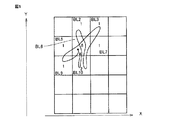
カウント部6は、各ブロックについて、ユーザの視線位置がブロックの外部からブロックの内部に移動した回数(つまり、視線の軌跡がブロック内に入った回数)をカウントする。図5の例では、ブロックBL2のカウント数が「1」で、ブロックBL3のカウント数が「1」で、ブロックBL5のカウント数が「1」で、ブロックBL6のカウント数が「6」で、ブロックBL7のカウント数が「1」で、ブロックBL9のカウント数が「1」で、ブロックBL10のカウント数が「2」である。
The
図6は、視線の軌跡を表わす図である。図6の例では、時刻t0に視線位置がブロックBL6で検出される。次に、時刻t1において、ユーザの視線位置がブロックBL10に移動する。さらに、時刻t2〜t12において、ユーザの視線位置がブロックBL9,BL5,BL6,BL2,BL3,BL7,BL6,BL10,BL6,BL2,BL6に移動する。 FIG. 6 is a diagram illustrating the locus of the line of sight. In the example of FIG. 6, the line-of-sight position is detected by the block BL6 at time t0. Next, at time t1, the user's line-of-sight position moves to block BL10. Further, at time t2 to t12, the user's line-of-sight position moves to blocks BL9, BL5, BL6, BL2, BL3, BL7, BL6, BL10, BL6, BL2, BL6.
また、カウント部6は、ユーザの視線位置が最初に検出されたブロックを基準ブロックBに設定し、基準ブロックBと基準ブロックBの近傍にある1個以上のブロックとを検出有効ゾーンDに設定する。カウント部6は、たとえば、基準ブロックBに縦、横、および斜め方向に隣接するブロックを基準ブロックBの近傍のブロックとする。カウント部6は、検出有効ゾーンDに含まれるブロックについてのみ、カウントを実施する。
The
カウント部6は、基準ブロックの遠隔にある1個以上のブロックをリセットゾーンRに設定する。カウント部6は、たとえば、X方向に3ブロック分離れているブロックと、Y方向に3ブロック分離れているブロックをリセットゾーンRに設定する。カウント部6は、ユーザの視線位置がリセットゾーンRに含まれるブロックに移動した場合には、全ブロックBL1〜BL20のカウント値を初期化する。
The
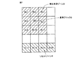
図7は、検出有効ゾーンDとリセットゾーンRの例を表わす図である。
図7に示すように、基準ブロックBが、ブロックBL6の場合には、ブロックBL6に隣接するブロックBL1,BL2,BL3,BL5,BL7,BL9,BL10,BL11が検出有効ゾーンDに設定される。また、Y方向に3ブロック分離れているブロックBL17〜BL20がリセットゾーンRに設定される。
FIG. 7 is a diagram illustrating an example of the detection effective zone D and the reset zone R.
As shown in FIG. 7, when the reference block B is the block BL6, the blocks BL1, BL2, BL3, BL5, BL7, BL9, BL10, BL11 adjacent to the block BL6 are set as the detection effective zone D. Also, the blocks BL17 to BL20 that are separated by three blocks in the Y direction are set as the reset zone R.
図8は、検出有効ゾーンDとリセットゾーンRの別の例を表わす図である。
図8に示すように、基準ブロックBが、ブロックBL1の場合には、ブロックBL1に隣接するブロックBL2,BL6が検出有効ゾーンDに設定される。また、X方向に3ブロック分離れているブロックBL4,BL8,BL12,BL16,BL20と、Y方向に3ブロック分離れているブロックBL13〜BL20(BL16とBL20は重複)がリセットゾーンRに設定される。
FIG. 8 is a diagram illustrating another example of the detection effective zone D and the reset zone R.
As shown in FIG. 8, when the reference block B is the block BL1, the blocks BL2 and BL6 adjacent to the block BL1 are set as the detection effective zone D. Also, the blocks BL4, BL8, BL12, BL16, and BL20 that are separated by 3 blocks in the X direction and the blocks BL13 to BL20 that are separated by 3 blocks in the Y direction (BL16 and BL20 overlap) are set as the reset zone R. The
アイコン選択部5は、カウント結果に基づいて、複数のアイコンのいずれかを選択する。より具体的には、アイコン選択部5は、カウント部6によるカウント値が所定値以上のブロックに含まれるアイコンを選択する。
The
プログラム実行部4は、選択されたアイコンに対応するプログラムを実行する。
本実施の形態では、従来技術による、ユーザの視線位置がブロックにどれだけの時間滞留したかによってアイコンを選択する方法(以下、注視時間に基づくアイコン選択方法)と、視線のふらつきを考慮して、ユーザの視線の軌跡がブロックを通過した回数によってアイコンを選択する方法(以下、視線の軌跡の通過回数に基づくアイコン選択方法)の2つの方法を併用して、アイコンを選択する。つまり、2つの方法を平行して実行し、いずれかの方法で先に選択されたアイコンがプログラム実行部4に通知されて、そのアイコンに対応するプログラムが実行される。
The
In the present embodiment, a method for selecting an icon according to how long the user's line-of-sight position stays in the block according to the prior art (hereinafter referred to as an icon selection method based on gaze time), and wandering of the line of sight are considered. The icon is selected by using two methods of selecting an icon according to the number of times that the user's line of sight trajectory has passed through the block (hereinafter referred to as an icon selection method based on the number of times the line of sight has passed). In other words, the two methods are executed in parallel, the icon previously selected by either method is notified to the
図9は、従来技術による注視時間に基づくアイコン選択の手順を表わすフローチャートである。 FIG. 9 is a flowchart showing a procedure for selecting an icon based on the gaze time according to the prior art.
ステップS901において、カウント部6は、全ブロックBL1〜BL20を検出有効ゾーンDに設定する。
In step S901, the
ステップS902において、検出有効ゾーンDのいずれかのブロック(当該ブロックをブロック*とする)に所定時間連続して視線位置が留まった場合に、処理がステップS903に進む。 In step S902, when the line-of-sight position remains in any block of the detection effective zone D (the block is referred to as a block *) for a predetermined time, the process proceeds to step S903.
ステップS903において、アイコン選択部5は、ブロック*に含まれるアイコンを選択する。
In step S903, the
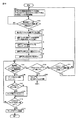
図10は、第1の実施形態による視線の軌跡がブロック内に入った回数に基づくアイコン選択の手順を表わすフローチャートである。 FIG. 10 is a flowchart showing an icon selection procedure based on the number of times the line-of-sight locus enters the block according to the first embodiment.
ステップS101において、カウント部6は、全ブロックBL1〜BL20を検出有効ゾーンDに設定する。カウント部6は、全ブロックBL1〜BL20のカウント値を0に初期化し、全ブロックBL1〜BL20のタイマを停止させる。また、カウント部6は、基準ブロックBが設定されている場合に、設定を解除する。
In step S101, the
ステップS102において、検出有効ゾーンDのいずれかのブロックで視線位置が初めて検出された場合に、処理がステップS103に進む。 In step S102, when the line-of-sight position is detected for the first time in any block of the detection effective zone D, the process proceeds to step S103.
ステップS103において、カウント部6は、視線位置が初めて検出されたブロックを基準ブロックBに設定する。
In step S <b> 103, the
ステップS104において、カウント部6は、図7または図8に示すように、基準ブロックBと、基準ブロックBの近傍の1個以上のブロックを検出有効ゾーンDに設定する。
In step S104, the
ステップS105において、カウント部6は、図7または図8に示すように、基準ブロックBの遠隔の1個以上のブロックをリセットゾーンRに設定する。
In step S105, the
ステップS106において、カウント部6は、基準ブロックBのカウント値をインクリメントする。
In step S106, the
ステップS107において、カウント部6は、基準ブロックBに設定されたブロック用のタイマをスタートさせる。
In step S107, the
ステップS108において、検出有効ゾーンDのいずれかのブロック(当該ブロックをブロック*とする)に視線位置が移動した場合には、処理がステップS109に進み、そのような条件が成立しない場合には、処理がステップS114に進む。 In step S108, when the line-of-sight position has moved to any block in the detection effective zone D (the block is referred to as a block *), the process proceeds to step S109, and when such a condition is not satisfied, The process proceeds to step S114.
ステップS109において、カウント部6は、ブロック*のカウント値をインクリメントする。
In step S109, the
ステップS110において、ブロック*のカウント値が「1」のときには、処理がステップS111に進み、そのような条件が成立しない場合には、処理がステップS112に進む。 In step S110, when the count value of the block * is “1”, the process proceeds to step S111, and when such a condition is not satisfied, the process proceeds to step S112.
ステップS111において、カウント部6は、ブロック*用のタイマをスタートさせる。
In step S111, the
ステップS112において、いずれかのブロック(当該ブロックをブロック**とする)のカウント値が所定値CT以上の場合には、処理がステップS113に進み、そのような条件が成立しない場合には、処理がステップS108に戻る。 In step S112, if the count value of any block (the block is referred to as block **) is greater than or equal to the predetermined value CT, the process proceeds to step S113, and if such a condition is not satisfied, the process is performed. Returns to step S108.
ステップS113において、アイコン選択部5は、ブロック**に含まれるアイコンを選択する。
In step S113, the
ステップS104において、いずれかのブロック(当該ブロックをブロック***とする)のタイマ値が所定値TM以上のときには、処理がステップS115に進み、そのような条件が成立しない場合には、処理がステップS116に進む。 In step S104, when the timer value of any block (the block is referred to as block ***) is equal to or greater than the predetermined value TM, the process proceeds to step S115, and when such a condition is not satisfied, the process is performed. Proceed to step S116.
ステップS115において、カウント部6は、ブロック***を検出有効ゾーンDから除外し、処理がステップ108に戻る。
In step S115, the
ステップS116において、リセットゾーンRのいずれかのブロックに視線位置が移動した場合には、処理がステップS101に戻り(すなわち、全ブロックが検出有効ゾーンDに設定され、全ブロックのカウント値が0に初期化され、全ブロックのタイマを停止させ、基準ブロックBの設定が解除される)、そのような条件が成立しない場合には、処理がステップS108に戻る。 If the line-of-sight position has moved to any block in the reset zone R in step S116, the process returns to step S101 (that is, all blocks are set to the detection effective zone D, and the count value of all blocks is set to 0). Initialization is performed, the timers of all blocks are stopped, and the setting of the reference block B is canceled). If such a condition is not satisfied, the process returns to step S108.
以上のように、本実施の形態によれば、視線の軌跡の入った回数が大きなブロックに含まれるアイコンが選択されるので、ユーザの視線がふらついたとしても、ユーザの視線によってアイコンを選択することができる。 As described above, according to the present embodiment, since an icon included in a block with a large number of times the line of sight has entered is selected, even if the user's line of sight fluctuates, the icon is selected based on the user's line of sight. be able to.
[第2の実施形態]
第2の実施形態は、検出有効ゾーンDの設定方法が第1の実施形態と相違する。
[Second Embodiment]
The second embodiment is different from the first embodiment in the method of setting the detection effective zone D.
本実施の形態のカウント部6は、複数のブロックのカウント値の中の最大値を特定し、特定した最大値との差が所定値以上のカウント値を有する1個以上のブロックを検出有効ゾーンDから除外する。
The
図11は、第2の実施形態による視線の軌跡がブロック内に入った回数に基づくアイコン選択の手順を表わすフローチャートである。 FIG. 11 is a flowchart showing an icon selection procedure based on the number of times the line-of-sight locus enters the block according to the second embodiment.
ステップS201において、カウント部6は、全ブロックBL1〜BL20を検出有効ゾーンDに設定する。カウント部6は、全ブロックBL1〜BL20のカウント値を0に初期化し、全ブロックBL1〜BL20のタイマを停止させる。
In step S201, the
ステップS202において、検出有効ゾーンDのいずれかのブロック(当該ブロックをブロック*とする)に視線位置が移動した場合に、処理がステップS203に進む。 In step S202, when the line-of-sight position has moved to any block in the detection effective zone D (this block is referred to as a block *), the process proceeds to step S203.
ステップS203において、カウント部6は、ブロック*のカウント値をインクリメントする。
In step S203, the
ステップS204において、ブロック*のカウント値が「1」のときには、処理がステップS205に進み、そのような条件が成立しない場合には、処理がステップS206に進む。 In step S204, when the count value of the block * is “1”, the process proceeds to step S205, and when such a condition is not satisfied, the process proceeds to step S206.
ステップS205において、カウント部6は、ブロック*用のタイマをスタートさせる。
In step S205, the
ステップS206において、いずれかのブロック(当該ブロックをブロック**とする)のカウント値が所定値CT以上の場合には、処理がステップS207に進み、そのような条件が成立しない場合には、処理がステップS208に進む。 In step S206, if the count value of any block (the block is referred to as block **) is greater than or equal to the predetermined value CT, the process proceeds to step S207, and if such a condition is not satisfied, the process is performed. Advances to step S208.
ステップS207において、アイコン選択部5は、ブロック**に含まれるアイコンを選択する。
In step S207, the
ステップS208において、いずれかのブロック(当該ブロックをブロック***とする)のカウント値と、最大のカウント値との差が所定値SAの場合には、処理がステップS209に進み、そのような条件が成立しない場合には、処理がステップS210に進む。 In step S208, if the difference between the count value of any block (the block is referred to as block ***) and the maximum count value is the predetermined value SA, the process proceeds to step S209, and such If the condition is not satisfied, the process proceeds to step S210.
ステップS209において、カウント部6は、ブロック***を検出有効ゾーンDから除外し、処理がステップ202に戻る。
In step S209, the
第2の実施形態では、時刻とともに各ブロックのカウント値が変化することに応じて、検出有効ゾーンDが変化する。図12を用いて、第2の実施形態による検出有効ゾーンDの変化について説明する。 In the second embodiment, the detection effective zone D changes as the count value of each block changes with time. A change in the detection effective zone D according to the second embodiment will be described with reference to FIG.
図12(a)に示すように、初期状態では、全ブロックBL1〜BL20が検出有効ゾーンDに設定される。 As shown in FIG. 12A, all blocks BL1 to BL20 are set in the detection effective zone D in the initial state.
図12(b)は、ブロックBL1〜BL20のカウント値の途中経過を表わす。
図12(c)に示すように、最大のカウント値(ここでは、「5」)との差が所定値SA(ここでは、「4」とする)以上のカウント値(ここでは、「0」および「1」)を有するブロックBL1,BL4,BL8,BL12〜BL20が検出有効ゾーンDから除外される。
FIG. 12B shows the progress of the count values of the blocks BL1 to BL20.
As shown in FIG. 12C, the difference from the maximum count value (here, “5”) is equal to or greater than a predetermined value SA (here, “4”) (here, “0”). And blocks BL1, BL4, BL8, and BL12 to BL20 having “1”) are excluded from the detection effective zone D.
視線の軌跡の各ブロックに入った回数をカウントしている過程で、カウント値が小さなブロックには、ユーザが選択を希望しているアイコンが含まれていないと推定される。本実施の形態では、これらのブロックを検出有効ゾーンから除外して、選択候補のアイコンを絞ることによって、より迅速かつ効率的に視線によるアイコンの選択が行える。 In the process of counting the number of times the line of sight has entered each block, it is estimated that the block with a small count value does not include the icon that the user wants to select. In this embodiment, by excluding these blocks from the detection effective zone and narrowing down selection candidate icons, it is possible to more quickly and efficiently select an icon based on the line of sight.
[第3の実施形態]
第3の実施形態は、視線位置がリセットゾーンRの外からリセットゾーンRに移動してから、実際にカウント値のリセットなどがなされるまでの手順が第1の実施形態と相違する。
[Third Embodiment]
The third embodiment is different from the first embodiment in the procedure from when the line-of-sight position moves from outside the reset zone R to the reset zone R until the count value is actually reset.
本実施の形態の選択部は、ユーザの視線位置がリセットゾーンRの外部からリセットゾーンRに所定回数移動した場合には、全ブロックのカウント値をリセットするとともに、基準ブロックBの設定をやり直す。 When the user's line-of-sight position moves from the outside of the reset zone R to the reset zone R a predetermined number of times, the selection unit according to the present embodiment resets the count values of all blocks and resets the reference block B.
図13は、第3の実施形態による視線の軌跡がブロック内に入った回数に基づくアイコン選択の手順を表わすフローチャートである。 FIG. 13 is a flowchart showing an icon selection procedure based on the number of times the line-of-sight locus enters the block according to the third embodiment.
ステップS301において、カウント部6は、第1の実施形態と同様に、全ブロックBL1〜BL20を検出有効ゾーンDに設定し、全ブロックBL1〜BL20のカウント値を0に初期化し、全ブロックBL1〜BL20のタイマを停止させる。さらに、カウント部6は、ユーザの視線位置がリセットゾーンRの外部からリセットゾーンRに移動した回数を表わすリセット用カウント値を0に初期化する。また、カウント部6は、基準ブロックBが設定されている場合に、設定を解除する。
In step S301, the
ステップS102〜S116の処理は、第1の実施形態と同様なので、説明を繰り返さない。 Since the processing of steps S102 to S116 is the same as that of the first embodiment, description thereof will not be repeated.
ステップS116において、リセットゾーンRのいずれかのブロックに視線位置が移動した場合には、処理がステップS302に進み、そのような条件が成立しない場合には、処理がステップS108に戻る。 In step S116, if the line-of-sight position has moved to any block in the reset zone R, the process proceeds to step S302. If such a condition is not satisfied, the process returns to step S108.
ステップS302において、カウント部6は、リセット用カウンタ値をインクリメントする。
In step S302, the
ステップS303において、リセット用カウント値が所定回数RC以上の場合には、処理がステップS301に戻り(すなわち、全ブロックが検出有効ゾーンDに設定され、全ブロックのカウント値およびリセット用カウント値が0に初期化され、全ブロックのタイマを停止させ、基準ブロックBの設定が解除される)、そのような条件が成立しない場合には、処理がステップS108に戻る。 In step S303, if the reset count value is equal to or greater than the predetermined number RC, the process returns to step S301 (that is, all blocks are set in the detection valid zone D, and the count value and reset count value of all blocks are 0). The timer of all blocks is stopped and the setting of the reference block B is canceled). If such a condition is not satisfied, the process returns to step S108.
以上のように、本実施の形態によれば、ユーザの視線位置がリセットゾーンRの外部からリセットゾーンRに所定回数移動した場合には、ユーザは、基準ブロックBの近傍のブロックに含まれるアイコンの選択を希望していない、あるいは、どのアイコンを選択するかをまだ決めていないと推定できる。そのような場合に、全ブロックのカウント値をリセットするとともに、もう一度最初から基準ブロックの設定をやり直すことによって、ユーザが希望するアイコンを迅速かつ効率的に選択することができる。 As described above, according to the present embodiment, when the user's line-of-sight position moves from the outside of the reset zone R to the reset zone R a predetermined number of times, the user includes the icons included in the blocks near the reference block B. It can be presumed that the user does not want to select or has not yet decided which icon to select. In such a case, the icon desired by the user can be selected quickly and efficiently by resetting the count values of all blocks and re-setting the reference block from the beginning.
[第4の実施形態]
第4の実施形態は、視線位置がリセットゾーンRの外からリセットゾーンRに移動してから、実際にカウント値のリセットなどがなされるまでの手順が第1、第3の実施形態と相違する。
[Fourth Embodiment]
The fourth embodiment is different from the first and third embodiments in the procedure from when the line-of-sight position moves from outside the reset zone R to the reset zone R until the count value is actually reset. .
本実施の形態の選択部は、ユーザの視線位置がリセットゾーンRの外部からリセットゾーンRに移動し、所定時間を超えてもユーザの視線位置がリセットゾーンRの外部へ移動しない場合に、全ブロックのカウント値をリセットするとともに、基準ブロックBの設定をやり直す。 The selection unit according to the present embodiment moves the user's line-of-sight position from the outside of the reset zone R to the reset zone R, and if the user's line-of-sight position does not move outside the reset zone R even after a predetermined time has elapsed, The block count value is reset, and the reference block B is set again.
図14は、第4の実施形態による視線の軌跡がブロック内に入った回数に基づくアイコン選択の手順を表わすフローチャートである。 FIG. 14 is a flowchart showing an icon selection procedure based on the number of times the line-of-sight locus enters the block according to the fourth embodiment.
ステップS101〜S116の処理は、第1の実施形態と同様なので、説明を繰り返さない。 Since the processing in steps S101 to S116 is the same as that in the first embodiment, description thereof will not be repeated.
ステップS116において、リセットゾーンRのいずれかのブロックに視線位置が移動した場合には、処理がステップS401に進み、そのような条件が成立しない場合には、処理がステップS108に戻る。 If the line-of-sight position has moved to any block in the reset zone R in step S116, the process proceeds to step S401. If such a condition is not satisfied, the process returns to step S108.
ステップS401において、所定時間TR以内に視線位置がリセットゾーンRの外部に移動した場合には、処理がステップS108に戻り、そのような条件が成立しない場合には、処理がステップS101に戻る。 If the line-of-sight position moves outside the reset zone R within the predetermined time TR in step S401, the process returns to step S108, and if such a condition is not satisfied, the process returns to step S101.
以上のように、本実施の形態によれば、 ユーザの視線位置がリセットゾーンRの外部からリセットゾーンRに移動してから所定時間を超えてもユーザの視線位置がリセットゾーンRの外部へ移動しない場合には、ユーザは、基準ブロックBの近傍のブロックに含まれるアイコンの選択を希望していない、あるいは、、どのアイコンを選択するかをまだ決めていないと推定できる。そのような場合に、全ブロックのカウント値をリセットするとともに、もう一度基準ブロックの設定をやり直すことによって、ユーザが希望するアイコンを迅速かつ効率的に選択することができる。 As described above, according to the present embodiment, the user's line-of-sight position moves to the outside of the reset zone R even if the user's line-of-sight position moves from the outside of the reset zone R to the reset zone R and exceeds a predetermined time. If not, it can be estimated that the user does not want to select an icon included in a block near the reference block B, or has not yet decided which icon to select. In such a case, the icon desired by the user can be selected quickly and efficiently by resetting the count values of all blocks and setting the reference block again.
(変形例)
本発明は、上記の実施形態に限定されるものではなく、たとえば以下のような変形例も含む。
(Modification)
The present invention is not limited to the above embodiment, and includes, for example, the following modifications.
(1)GUIの選択
本発明の実施形態では、各ブロックにアイコンが含まれ、ユーザの視線位置によってブロックに含まれるアイコンが選択され、アイコンに対応するプログラムが実行されることとしたが、これに限定されるものではない。各ブロックにGUIが含まれ、ユーザの視線位置によって、ブロックに含まれるGUIが選択され、GUIに対応するプログラムが実行されることとしてもよい。GUIには、アイコン以外にも、メニューの各項目、ボタン、ウィジェット、その他操作可能な表示オブジェクトなどが含まれる。
(1) Selection of GUI In the embodiment of the present invention, an icon is included in each block, an icon included in the block is selected according to the user's line-of-sight position, and a program corresponding to the icon is executed. It is not limited to. A GUI may be included in each block, a GUI included in the block may be selected according to the user's line-of-sight position, and a program corresponding to the GUI may be executed. In addition to icons, the GUI includes menu items, buttons, widgets, and other display objects that can be operated.
(2)注視時間と視線の軌跡の通過回数とを組み合わせた選択方法
本発明の実施形態では、注視時間に基づくアイコン選択方法(第1の方法)と、視線の軌跡の通過回数に基づくアイコン選択方法(第2の方法)の2つの方法を平行して実行し、いずれかの方法で先に選択されたアイコンがプログラム実行部4に通知されて、そのアイコンに対応するプログラムが実行されることとしたが、これに限定されるものではない。
(2) Selection Method Combining Gaze Time and Number of Passes of Gaze Trajectory In the embodiment of the present invention, an icon selection method based on gaze time (first method) and icon selection based on the number of passes of the gaze trajectory Two methods (second method) are executed in parallel, the icon previously selected by any of the methods is notified to the
第1の方法による各ブロックの視線の滞留時間Xと、第2の方法による各ブロックのカウント値Yとを重みづけ加算して、各ブロックの評価値Zを求め、評価値Zが所定値以上のブロックに対応するアイコンを選択するものとしてもよい。 Weighted addition of the line-of-sight residence time X of each block according to the first method and the count value Y of each block according to the second method to obtain an evaluation value Z of each block, and the evaluation value Z is equal to or greater than a predetermined value The icon corresponding to the block may be selected.
今回開示された実施の形態はすべての点で例示であって制限的なものではないと考えられるべきである。本発明の範囲は上記した説明ではなくて特許請求の範囲によって示され、特許請求の範囲と均等の意味および範囲内でのすべての変更が含まれることが意図される。 The embodiment disclosed this time should be considered as illustrative in all points and not restrictive. The scope of the present invention is defined by the terms of the claims, rather than the description above, and is intended to include any modifications within the scope and meaning equivalent to the terms of the claims.
1 電子機器、2 アンテナ、3 表示部、4 プログラム実行部、5 アイコン選択部、6 カウント部、7 視線検出部、8 無線通信部、32 赤外線LED、30 赤外線カメラ。
DESCRIPTION OF
Claims (8)
前記表示部の表示面上への視線の入力位置を検出する視線検出部と、
前記視線の入力位置がいずれかのブロックの外部から内部に移動した回数をカウントするカウント部と、
カウントされたカウント値が所定値以上のブロックに含まれるGUIに対応する処理を実行する実行部と、
を備える、電子機器。 A display unit for displaying an image, a plurality of blocks are set in the image, and the block includes a GUI.
A line-of-sight detection unit that detects an input position of the line of sight on the display surface of the display unit;
A counting unit that counts the number of times the line-of-sight input position has moved from the outside to the inside of any block;
An execution unit that executes processing corresponding to a GUI included in a block in which the counted value is equal to or greater than a predetermined value;
An electronic device.
前記カウント部は、前記検出有効ゾーンに含まれる各ブロックについて、前記カウントを行なう、請求項1記載の電子機器。 The counting unit sets a block in which the line-of-sight input position is first detected as a reference block, sets the reference block and one or more blocks in the vicinity of the reference block as a detection effective zone,
The electronic device according to claim 1, wherein the count unit performs the count for each block included in the detection effective zone.
前記カウント部は、前記視線の入力位置が前記リセットゾーンに移動した場合に、全ブロックの前記カウント値をリセットするとともに、前記基準ブロックの設定をやり直す、請求項3記載の電子機器。 The selection unit sets one or more blocks remote from the reference block as a reset zone,
The electronic device according to claim 3, wherein when the line-of-sight input position moves to the reset zone, the count unit resets the count values of all blocks and resets the reference block.
前記選択部は、前記視線の入力位置が前記リセットゾーンの外部から前記リセットゾーンに所定回数移動した場合には、前記カウント値をリセットするとともに、前記基準ブロックの設定をやり直す、請求項3記載の電子機器。 The selection unit sets one or more blocks remote from the reference block as a reset zone,
The said selection part resets the said count value, and resets the setting of the said reference block, when the input position of the said line of sight moves to the said reset zone from the reset zone a predetermined number of times. Electronics.
前記選択部は、前記視線の入力位置が前記リセットゾーンの外部から前記リセットゾーンに移動し、所定時間を超えても前記視線の入力位置が前記リセットゾーンの外部へ移動しない場合に、前記カウント値をリセットするとともに、前記基準ブロックの設定をやり直す、請求項3記載の電子機器。 The selection unit sets one or more blocks remote from the reference block as a reset zone,
When the line-of-sight input position moves from the outside of the reset zone to the reset zone, and the line-of-sight input position does not move outside the reset zone even after a predetermined time has elapsed, The electronic apparatus according to claim 3, wherein the reference block is set again.
前記画像には複数のブロックが設定され、ブロックにはGUIが含まれ、
前記表示部の表示面上への視線の入力位置を検出するステップと、
前記視線の入力位置がいずれかのブロックの外部から内部に移動した回数をカウントするステップと、
カウントされたカウント値が所定値以上のブロックに含まれるGUIに対応する処理を実行するステップと、
を備える、視線入力方法。 An eye-gaze input method for an electronic device including a display unit for displaying an image,
A plurality of blocks are set in the image, and the block includes a GUI.
Detecting an input position of a line of sight on the display surface of the display unit;
Counting the number of times the line-of-sight input position has moved from the outside of any block to the inside;
Executing a process corresponding to a GUI included in a block having a counted value equal to or greater than a predetermined value;
A line-of-sight input method.
Priority Applications (1)
| Application Number | Priority Date | Filing Date | Title |
|---|---|---|---|
| JP2013244973A JP6088961B2 (en) | 2013-11-27 | 2013-11-27 | Electronic device and line-of-sight input method |
Applications Claiming Priority (1)
| Application Number | Priority Date | Filing Date | Title |
|---|---|---|---|
| JP2013244973A JP6088961B2 (en) | 2013-11-27 | 2013-11-27 | Electronic device and line-of-sight input method |
Publications (2)
| Publication Number | Publication Date |
|---|---|
| JP2015103152A true JP2015103152A (en) | 2015-06-04 |
| JP6088961B2 JP6088961B2 (en) | 2017-03-01 |
Family
ID=53378770
Family Applications (1)
| Application Number | Title | Priority Date | Filing Date |
|---|---|---|---|
| JP2013244973A Active JP6088961B2 (en) | 2013-11-27 | 2013-11-27 | Electronic device and line-of-sight input method |
Country Status (1)
| Country | Link |
|---|---|
| JP (1) | JP6088961B2 (en) |
Cited By (4)
| Publication number | Priority date | Publication date | Assignee | Title |
|---|---|---|---|---|
| JP2017146941A (en) * | 2016-02-19 | 2017-08-24 | 富士通株式会社 | Image display device, display control method and display control program |
| JP2018085124A (en) * | 2017-12-28 | 2018-05-31 | 株式会社コナミデジタルエンタテインメント | Terminal device and program |
| JP2018084875A (en) * | 2016-11-21 | 2018-05-31 | 株式会社コナミデジタルエンタテインメント | Terminal device and program |
| JP2018085125A (en) * | 2017-12-28 | 2018-05-31 | 株式会社コナミデジタルエンタテインメント | Terminal device and program |
Citations (5)
| Publication number | Priority date | Publication date | Assignee | Title |
|---|---|---|---|---|
| JPH03109030A (en) * | 1989-09-22 | 1991-05-09 | Canon Inc | Noting point detector |
| JPH07248872A (en) * | 1994-03-11 | 1995-09-26 | Matsushita Electric Ind Co Ltd | Input device and arithmetic input / output device |
| JPH07283974A (en) * | 1994-04-12 | 1995-10-27 | Canon Inc | Video camera with eye-gaze detector |
| JPH08272517A (en) * | 1995-03-28 | 1996-10-18 | Sanyo Electric Co Ltd | Device and method for selecting sight line correspondence and information processor |
| JP2001350578A (en) * | 2000-06-06 | 2001-12-21 | Sensor:Kk | Device and method for input control by visual line and recording medium with control program to be inputted by visual line recorded thereon |
-
2013
- 2013-11-27 JP JP2013244973A patent/JP6088961B2/en active Active
Patent Citations (5)
| Publication number | Priority date | Publication date | Assignee | Title |
|---|---|---|---|---|
| JPH03109030A (en) * | 1989-09-22 | 1991-05-09 | Canon Inc | Noting point detector |
| JPH07248872A (en) * | 1994-03-11 | 1995-09-26 | Matsushita Electric Ind Co Ltd | Input device and arithmetic input / output device |
| JPH07283974A (en) * | 1994-04-12 | 1995-10-27 | Canon Inc | Video camera with eye-gaze detector |
| JPH08272517A (en) * | 1995-03-28 | 1996-10-18 | Sanyo Electric Co Ltd | Device and method for selecting sight line correspondence and information processor |
| JP2001350578A (en) * | 2000-06-06 | 2001-12-21 | Sensor:Kk | Device and method for input control by visual line and recording medium with control program to be inputted by visual line recorded thereon |
Cited By (4)
| Publication number | Priority date | Publication date | Assignee | Title |
|---|---|---|---|---|
| JP2017146941A (en) * | 2016-02-19 | 2017-08-24 | 富士通株式会社 | Image display device, display control method and display control program |
| JP2018084875A (en) * | 2016-11-21 | 2018-05-31 | 株式会社コナミデジタルエンタテインメント | Terminal device and program |
| JP2018085124A (en) * | 2017-12-28 | 2018-05-31 | 株式会社コナミデジタルエンタテインメント | Terminal device and program |
| JP2018085125A (en) * | 2017-12-28 | 2018-05-31 | 株式会社コナミデジタルエンタテインメント | Terminal device and program |
Also Published As
| Publication number | Publication date |
|---|---|
| JP6088961B2 (en) | 2017-03-01 |
Similar Documents
| Publication | Publication Date | Title |
|---|---|---|
| EP4239456B1 (en) | Method and glasses type wearable device for providing a virtual input interface | |
| CN109656354B (en) | Information processing apparatus, information processing method, and computer program | |
| KR102153006B1 (en) | Method for processing input and an electronic device thereof | |
| US20160292922A1 (en) | Display control device, display control method, and recording medium | |
| JP6088961B2 (en) | Electronic device and line-of-sight input method | |
| JP6301613B2 (en) | Mobile communication terminal, information display program, and information display method | |
| KR20120096849A (en) | An apparatus and method for inputting command using gesture | |
| US20150091824A1 (en) | Information processing apparatus, information processing method, and computer program | |
| CN103927101B (en) | The method and apparatus of operational controls | |
| EP2921947A1 (en) | Device and method for controlling a display panel | |
| KR20160088620A (en) | Virtual input apparatus and method for receiving user input using thereof | |
| EP3021206B1 (en) | Method and device for refocusing multiple depth intervals, and electronic device | |
| WO2012169155A1 (en) | Information processing terminal and method, program, and recording medium | |
| JP6426755B2 (en) | Operation processing method, device, program, and recording medium | |
| JP2014215838A (en) | Portable electronic equipment | |
| US20140210728A1 (en) | Fingerprint driven profiling | |
| JP2015501052A5 (en) | ||
| US10437415B2 (en) | System, method, and device for controlling a display | |
| CN108139858A (en) | Secure identification information input on small-sized touch-screen display | |
| US11157085B2 (en) | Method and apparatus for switching display mode, mobile terminal and storage medium | |
| JP5989942B2 (en) | BACKGROUND DISPLAY METHOD, DEVICE, ELECTRONIC DEVICE, PROGRAM, AND RECORDING MEDIUM | |
| CN106249886A (en) | Menu display method and device | |
| KR101708455B1 (en) | Hand Float Menu System | |
| JP6130922B2 (en) | Electronic device, control program, and operation method of electronic device | |
| CN109308113A (en) | Non-contact input device and method, display capable of non-contact input |
Legal Events
| Date | Code | Title | Description |
|---|---|---|---|
| A621 | Written request for application examination |
Free format text: JAPANESE INTERMEDIATE CODE: A621 Effective date: 20160217 |
|
| A977 | Report on retrieval |
Free format text: JAPANESE INTERMEDIATE CODE: A971007 Effective date: 20161125 |
|
| A131 | Notification of reasons for refusal |
Free format text: JAPANESE INTERMEDIATE CODE: A131 Effective date: 20161220 |
|
| A521 | Request for written amendment filed |
Free format text: JAPANESE INTERMEDIATE CODE: A523 Effective date: 20170116 |
|
| TRDD | Decision of grant or rejection written | ||
| A01 | Written decision to grant a patent or to grant a registration (utility model) |
Free format text: JAPANESE INTERMEDIATE CODE: A01 Effective date: 20170131 |
|
| A61 | First payment of annual fees (during grant procedure) |
Free format text: JAPANESE INTERMEDIATE CODE: A61 Effective date: 20170206 |
|
| R150 | Certificate of patent or registration of utility model |
Ref document number: 6088961 Country of ref document: JP Free format text: JAPANESE INTERMEDIATE CODE: R150 |