JP2015111069A - Radioactivity inspection apparatus and method - Google Patents
Radioactivity inspection apparatus and method Download PDFInfo
- Publication number
- JP2015111069A JP2015111069A JP2013253246A JP2013253246A JP2015111069A JP 2015111069 A JP2015111069 A JP 2015111069A JP 2013253246 A JP2013253246 A JP 2013253246A JP 2013253246 A JP2013253246 A JP 2013253246A JP 2015111069 A JP2015111069 A JP 2015111069A
- Authority
- JP
- Japan
- Prior art keywords
- radioactivity
- radiation
- uneven distribution
- detector
- container
- Prior art date
- Legal status (The legal status is an assumption and is not a legal conclusion. Google has not performed a legal analysis and makes no representation as to the accuracy of the status listed.)
- Granted
Links
Images

Landscapes
- Measurement Of Radiation (AREA)
Abstract
Description
本発明の実施形態は、容器に収納された測定対象物の放射能量を測定する放射能検査装置及び方法に関する。 Embodiments described herein relate generally to a radioactivity inspection apparatus and method for measuring a radioactivity amount of a measurement object housed in a container.
環境中、例えば土壌や食品等に存在する放射能量は、少量のサンプリング分析による検査が昨今まで実施されてきたが、原子力発電所の事故に伴い一般環境中に大量の放射能が放出されたことで、大量の汚染土壌や廃棄物、あるいは食品等に対する放射能の全数検査が必要になってきた。この場合、放射線サーベイメータによるマニュアル測定では物量的に限界があるため、多数の対象物を高速に自動で測定できる装置が要求される。 The amount of radioactivity present in the environment, such as soil and food, has been examined by a small amount of sampling analysis until now, but a large amount of radioactivity was released into the general environment due to an accident at a nuclear power plant. Therefore, it has become necessary to conduct a complete inspection of radioactivity on a large amount of contaminated soil, waste, or food. In this case, since manual measurement using a radiation survey meter is limited in quantity, an apparatus capable of automatically measuring a large number of objects at high speed is required.
これに対応する従来技術として、例えば原子力施設の放射線管理で使用されている物品搬出モニタがある。これは、ローラコンベア上の大型のトレイに複数の物品を並べてβ線検出器まで搬送し、一度に短時間で物品表面の放射能密度を測定して放射能の有無を検査する装置である。主に物品の表面から放出されるβ線を検出して表面放射能密度に換算し、更に、補助的にγ線検出器を用いて物品内部の放射能量を検出する。この装置はβ線による物品表面の放射能検査が主体であるため、厚みのある大型の対象物の検査には不向きである。 As a conventional technique corresponding to this, for example, there is an article carry-out monitor used in radiation management of a nuclear facility. This is a device for inspecting the presence or absence of radioactivity by measuring the radioactivity density on the surface of an article in a short time at a time, arranging a plurality of articles on a large tray on a roller conveyor and transporting them to a β-ray detector. Β-rays emitted mainly from the surface of the article are detected and converted to surface radioactivity density, and further, the amount of radioactivity inside the article is detected using a γ-ray detector as an auxiliary. Since this apparatus mainly performs radioactivity inspection on the surface of an article using β-rays, it is not suitable for inspection of a thick and large object.
また、大型の廃棄物や大量の廃棄物を一括で検査する装置として原子力施設で使用されるものとしては、200Lドラム缶や大型角型容器に収納された放射性廃棄物の検査装置がある。これは、ドラム缶などに収納された廃棄物から発生するγ線をスペクトル測定して放射能量に換算するものであり、市販されているものはいずれも容器を駆動する機構部も含めて大型の検査装置となっている。 In addition, as a device for inspecting large waste and a large amount of waste in a nuclear facility, there are inspection devices for radioactive waste stored in a 200 L drum can or a large rectangular container. This is to measure the γ-rays generated from the waste stored in drums etc. and convert it into radioactivity, and all the commercially available ones include large-scale inspections including the mechanism that drives the container. It is a device.
これらの装置は、測定対象となる容器内の廃棄物に放射能の偏りがあるとγ線の廃棄物中の透過距離に差が生じるため、同じ放射能濃度であっても容器中心付近に放射能が集中する場合には、廃棄物によるγ線吸収の影響で著しくγ線検出感度が低下し、逆に、検出器前面付近に放射能が集中する場合には、γ線がほとんど吸収されずにγ線検出器に入射するためγ線の検出感度が大きくなる。このように廃棄物を収納した容器に放射能の偏りがある場合には、γ線の検出感度が大幅に変動することによって放射能量の測定誤差が増大することから、従来からいくつかの補正手段が提案されてきた。 In these devices, if the waste in the container to be measured has a radioactivity bias, there will be a difference in the transmission distance of the gamma ray through the waste. When the activity is concentrated, the sensitivity of γ-ray detection is significantly reduced due to the effect of γ-ray absorption by the waste. Conversely, when the radioactivity is concentrated near the front of the detector, almost no γ-ray is absorbed. Since the light is incident on the γ-ray detector, the detection sensitivity of γ-ray increases. When there is a bias in radioactivity in the container that contains waste in this way, the measurement error of the radioactivity amount increases due to a significant fluctuation in the detection sensitivity of γ-rays. Has been proposed.
その中で最も単純な方法は、廃棄物が収納された容器を回転させながら測定することで、放射能の周方向の偏りを均一化させようというものである。ドラム缶では連続回転させるのが一般的であるが、角型容器の場合には例えば90°毎に容器を間欠回転させて測定することもある。 The simplest method among them is to make the deviation in the circumferential direction of radioactivity uniform by measuring while rotating the container in which the waste is stored. In general, the drum can be continuously rotated, but in the case of a rectangular container, the measurement may be performed by intermittently rotating the container every 90 °, for example.
容器の回転だけでは放射能の径方向の偏りについて補正できないため、更に別の方法と組み合わせて補正する場合がある。その一つであるエミッションCT法は放射線の発生位置をCT法で特定するものであり、密度分布の影響を受けるものの詳細な放射能分布を求めることが可能である。しかしながら、CTスキャン用にγ線検出器とコリメータが多数必要になるため、装置規模が大型化してしまう。 Since the radial deviation of radioactivity cannot be corrected only by rotating the container, it may be corrected in combination with another method. One of them, the emission CT method, is to specify the radiation generation position by the CT method, and it is possible to obtain a detailed radioactivity distribution although it is affected by the density distribution. However, since a large number of γ-ray detectors and collimators are required for CT scanning, the apparatus scale is increased.
その他、γ線エネルギスペクトルの光電ピーク計数率と散乱線計数率との比から線源位置を推定する方法や、2つ以上のγ線を放出する核種、例えばCo−60やEu−154などが対象の場合に、それぞれのγ線におけるエネルギスペクトルの光電ピーク計数率の比から線源位置を推定する方法が用いられている。この場合、容器を回転させないで、例えば測定対象物を横方向に何分割かして各分割区分毎に測定を行い、予め求めておいた散乱線計数率などのγ線検出器の応答関数を用いて線源位置を推定する方法がある。 In addition, there are methods for estimating the source position from the ratio between the photoelectric peak count rate and the scattered ray count rate of the γ-ray energy spectrum, and nuclides that emit two or more γ rays, such as Co-60 and Eu-154. In the case of an object, a method is used in which the source position is estimated from the ratio of the photoelectric peak count rate of the energy spectrum in each γ-ray. In this case, without rotating the container, for example, the object to be measured is divided into several parts in the horizontal direction and measurement is performed for each divided section, and the response function of the γ-ray detector such as the scattered ray count rate obtained in advance is obtained. There is a method for estimating the position of the radiation source by using it.
しかしながら、前述のような放射能分布の偏りを補正する従来技術の第1の課題は、容器を連続回転させるか、あるいは測定対象物を分割して各分割区分毎に測定するための機構部が必要になり、また、特にエミッションCT法の場合には、γ線検出器やコリメータの台数も多くなることから、装置規模が大型且つ複雑になって、コストが上昇する点である。 However, the first problem of the prior art for correcting the bias of the radioactivity distribution as described above is that a mechanism unit for continuously rotating the container or dividing the measurement object and measuring for each divided section. In particular, in the case of the emission CT method, since the number of γ-ray detectors and collimators increases, the scale of the apparatus becomes large and complicated, and the cost increases.
また、第2の課題は、原子力発電所事故に由来の現実的な廃棄物の場合には、放射能の局所的な偏りではなく緩やかな放射能分布であって、主要核種がγ線エネルギスペクトルにおいて単一のピークを呈するCs−137であると考えられるので、従来の散乱線計数率をピーク計数率と共に用いるだけの補正では線源位置の明確な推定が難しく、更に、複数のγ線エネルギを用いる従来の補正は適用できない点である。 The second problem is that in the case of realistic waste resulting from a nuclear power plant accident, it is not a local bias of radioactivity but a gentle radioactivity distribution, and the main nuclide is a γ-ray energy spectrum. Since it is considered that Cs-137 exhibits a single peak at the same time, it is difficult to clearly estimate the source position by correction using only the conventional scattered ray count rate together with the peak count rate. The conventional correction using the is not applicable.
本発明における実施形態の目的は、上述の事情を考慮してなされたものであり、放射線を放出する測定対象物が収納された容器について、比較的簡単な構成により放射能の偏在による放射能量の測定誤差を低減できる放射能検査装置及び方法を提供することにある。 The object of the embodiment of the present invention is made in consideration of the above-mentioned circumstances, and the amount of radioactivity due to the uneven distribution of radioactivity is measured with a relatively simple configuration for a container in which a measurement object that emits radiation is stored. An object of the present invention is to provide a radioactivity inspection apparatus and method that can reduce measurement errors.
本発明の実施形態における放射能検査装置は、容器に収納された測定対象物から放出される放射線を検出して放射線信号を出力すると共に、前記容器との相対位置を変更可能な放射線検出器と、この放射線検出器が前記容器との複数の相対位置毎に出力した放射線信号を計数すると共に、この放射線計数値から検出器応答パターンを求める放射線計数手段と、前記容器に収納された前記測定対象物の複数種類の放射能偏在パターン、及びこの複数種類の放射能偏在パターンのそれぞれに対応する複数種類の推定用検出器応答パターンを予め記憶する偏在パターン記憶手段と、前記放射線計数手段で求めた検出器応答パターンと前記偏在パターン記憶手段に予め記憶された複数種類の推定用検出器応答パターンとを照合し、いずれかの推定用検出器応答パターンに対応する放射能偏在パターンを選択する偏在パターン推定手段と、この偏在パターン推定手段にて選択された放射能偏在パターンに関連づけて設定された放射能換算係数を用いて、前記放射線計数手段にて計数された放射線計数値から前記容器の放射能量を算出する放射能算出手段と、を有することを特徴とするものである。 A radioactivity inspection apparatus according to an embodiment of the present invention detects a radiation emitted from an object to be measured housed in a container and outputs a radiation signal, and a radiation detector capable of changing a relative position with the container. The radiation detector counts the radiation signal output for each of a plurality of relative positions with respect to the container, and obtains a detector response pattern from the radiation count value, and the measurement object stored in the container A plurality of types of radioactive uneven distribution patterns of objects, and a plurality of types of estimation detector response patterns corresponding to each of the plurality of types of radioactive uneven distribution patterns are preliminarily stored, and obtained by the radiation counting unit. A detector response pattern is collated with a plurality of types of estimation detector response patterns stored in advance in the uneven distribution pattern storage means, and one of the estimation detection patterns is checked. The radiation count using the uneven distribution pattern estimation means for selecting the radiation uneven distribution pattern corresponding to the response pattern of the vessel and the radioactivity conversion coefficient set in association with the radiation uneven distribution pattern selected by the uneven distribution pattern estimation means And a radioactivity calculating means for calculating the radioactivity amount of the container from the radiation count value counted by the means.
本発明の実施形態における放射能検査方法は、放射線を放出する測定対象物が収納された容器の周囲複数位置で放射線検出器が放射線を検出して放射線信号を出力し、この放射線信号を計数した放射線計数値から検出器応答パターンを求め、この検出器応答パターンを用いて、前記容器に収納された前記測定対象物の放射能偏在パターンを推定し、この放射能偏在パターンに関連づけて設定された放射能換算計数を用いて、前記放射線計数値から前記容器の放射能量を算出することを特徴とするものである。 In the radioactivity inspection method according to the embodiment of the present invention, a radiation detector detects radiation at a plurality of positions around a container in which a measurement object that emits radiation is stored, outputs a radiation signal, and counts the radiation signal. A detector response pattern is obtained from the radiation count value, and using this detector response pattern, the radioactivity uneven distribution pattern of the measurement object stored in the container is estimated, and the radioactivity uneven distribution pattern is set in association with the radioactivity distribution pattern. The radioactivity amount of the container is calculated from the radiation count value using a radioactivity conversion count.
上述の如く説明した実施形態によれば、放射線を放出する測定対象物が収納された容器について、比較的簡単な構成により放射能の偏在による放射能量の測定誤差を低減できる。 According to the embodiment described above, the measurement error of the radioactivity amount due to the uneven distribution of radioactivity can be reduced with a relatively simple configuration for the container in which the measurement object that emits radiation is stored.
以下、本発明を実施するための形態を、図面に基づき説明する。
[A]第1実施形態(図1〜図3)
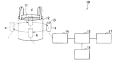
図1は、第1実施形態に係る放射能検査装置を示す構成図である。本第1実施形態の放射能検査装置10は、容器12に収納された測定対象物としての廃棄物11から放出される放射線を検出し放射線信号を出力すると共に、容器12の側面における周方向の相対位置を変更可能な放射線検出器13と、この放射線検出器13の後段に設けられた放射線計数手段14と、この放射線計数手段14の後段に設けられた偏在パターン推定手段15と、この偏在パターン推定手段15に接続された偏在パターン記憶手段16と、偏在パターン推定手段15の後段に設けられた放射能算出手段17と、を有して構成される。
Hereinafter, embodiments for carrying out the present invention will be described with reference to the drawings.
[A] First embodiment (FIGS. 1 to 3)
FIG. 1 is a configuration diagram showing a radioactivity inspection apparatus according to the first embodiment. The
容器12は、例えば200Lドラム缶やフレキシブルコンテナバッグなどの大型の廃棄物容器である。この容器12に収納された廃棄物11は放射線であるγ線を放出し、このγ線は、廃棄物11自体や容器12に吸収されつつ放射線検出器13に入射される。
The
放射線検出器13は、放射線としてのγ線を検出するγ線検出器であり、一般的に、NaI(Tl)シンチレーション検出器やGe半導体検出器などが使用されるが、γ線エネルギ情報が得られれば特に種類は限定しない。放射線検出手段13は、容器12の側面に対する相対位置が可変であり、図1の例では容器12の周方向複数位置、つまり位置aを原点として、90°毎にb、c、dの各位置でγ線を検出する。また、放射線検出器13は、入射したγ線エネルギに比例した放射線信号(例えば波高値のパルス)を出力し、この放射線信号が放射線計数手段14で計数される。
The
放射線計数手段14は例えば多重波高分析器であり、放射線検出器13が容器12との複数の相対位置(前述の位置a、b、c、d)毎にγ線を検出して出力した放射線信号を計数して、放射線検出器13の相対位置毎にγ線エネルギスペクトルを計測する。更に、放射線計数手段14は、計測した相対位置毎のγ線エネルギスペクトルから放射線計数値(即ち放射線検出器13の相対位置毎のγ線エネルギスペクトルのピーク計数率、散乱領域計数率)を求め、この放射線計数値から検出器応答パターンを演算する。
The radiation counting means 14 is, for example, a multiwave height analyzer, and the
この検出器応答パターンは、放射線検出器13の対向する相対位置(例えば位置aとc、位置bとd)でのγ線エネルギスペクトルにおける光電ピーク計数率の比、放射線検出器13の隣接する相対位置(例えば位置aとc、位置cとd)でのγ線エネルギスペクトルにおける光電ピーク計数率の比、放射線検出器13のそれぞれの相対位置(即ち位置a、b、c、d)でのγ線エネルギスペクトルにおける光電ピーク計数と散乱領域計数率との比、が組み合わされたものである。この検出器応答パターンでは、各計数率の比の数値は相対値を用いてもよい。
This detector response pattern shows the ratio of the photoelectric peak count rate in the γ-ray energy spectrum at the opposite relative positions of the radiation detector 13 (for example, positions a and c, positions b and d), and the relative positions adjacent to the
各位置a〜dでのγ線エネルギスペクトルの光電ピーク計数率を、対向する位置、隣接する位置で比較することにより、廃棄物11の放射能量によらずに、容器12内での周方向の計数率分布を求めることができる。
By comparing the photoelectric peak count rate of the γ-ray energy spectrum at each position a to d at the opposite position and the adjacent position, the circumferential direction in the
また、各位置a〜dでのγ線エネルギスペクトルの光電ピーク計数率と散乱領域計数率とを比較することにより、容器12内の深さ方向(半径方向)に対する線源位置を求めることができる。
Further, the source position in the depth direction (radial direction) in the
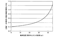
例えば、図2は、密度1.3g/cm3の廃棄物11からのγ線を計測したときの容器12内のCs−137の線源位置と、NaI(Tl)シンチレーション検出器を用いたCs−137からのγ線エネルギスペクトルの光電ピーク計数率と散乱線領域計数率の比との関係を示す。容器12の中心付近にある線源からのγ線は、廃棄物11による吸収や散乱の影響を受けるので、γ線エネルギスペクトルの光電ピーク計数率が小さくなり、代わりに散乱領域計数率が増加する。一方、容器12の表面付近にある線源からのγ線は、上述の吸収等の影響をほとんど受けないため、γ線エネルギスペクトルのピーク計数率が大きくなる。また、容器12内に放射能が均一に分布している場合におけるγ線エネルギスペクトルの光電ピーク計数率と散乱領域計数率との比は、線源が容器12の中心付近にある場合と表面付近にある場合との中間に相当し、図2の例では略0.5付近になる。
For example, FIG. 2 shows the source position of Cs-137 in the
ここで、図2は一例であり、光電ピーク計数率と散乱領域計数率との比と線源位置との関係は、実際には容器12内の廃棄物11の材質や容器12内での廃棄物11の密度、容器12の形状などによって変化する。
Here, FIG. 2 is an example, and the relationship between the ratio between the photoelectric peak count rate and the scattering region count rate and the source position is actually the material of the waste 11 in the
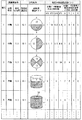
偏在パターン記憶手段16は、図3に示すように、容器12の形状や容器12内での廃棄物11の密度などの廃棄物条件と、容器12に収納された廃棄物11の放射能濃度比や、容器12に収納された廃棄物11の複数種類の放射能偏在パターンなどの分布条件と、放射能偏在パターンのそれぞれに対応すると共に、放射線検出器13の各相対位置について求められた複数種類の推定用検出器応答パターンと、を予め関連づけて記憶する。
As shown in FIG. 3, the uneven distribution pattern storage means 16 includes waste conditions such as the shape of the
このうち、推定用検出器応答パターンは、放射線計数手段14が求める検出器応答パターンと整合するものであり、放射線検出器13の対向する相対位置(例えば位置aとc、位置bとd)でのγ線エネルギスペクトルにおける光電ピーク計数率の比、放射線検出器13の隣接する相対位置(例えば位置aとc、位置cとd)でのγ線エネルギスペクトルにおける光電ピーク計数率の比、放射線検出器13のそれぞれの相対位置(即ち位置a、b、c、d)でのγ線エネルギスペクトルにおける光電ピーク計数率と散乱領域計数率との比、が組み合わされたものである。
Among these, the estimation detector response pattern is matched with the detector response pattern obtained by the radiation counting means 14, and at the relative positions (for example, positions a and c, positions b and d) of the
この推定用検出器応答パターンの数値は、予め標準放射線源と模擬廃棄物とを組み合わせて実際に測定することで算出してもよく、またはシミュレーション計算により算出してもよい。この推定検出器応答パターンでも、各計数率の比の数値は相対値を用いてもよい。 The numerical value of the estimation detector response pattern may be calculated by actually measuring in advance a combination of the standard radiation source and the simulated waste, or may be calculated by simulation calculation. Even in this estimated detector response pattern, a relative value may be used as the numerical value of the ratio of each count rate.
また、放射能偏在パターンは、放射線検出器13の配置と廃棄物11の容器12内での収納状態とに応じて、実際に想定される容器12内での廃棄物11の分布パターンから予め決定しておけばよい。図3では、円筒形状の容器12を周方向、高さ方向、径方向のそれぞれに分割したパターンの一例を示しており、白の領域の放射能濃度が、斜線領域の放射能濃度の10倍に設定されている。分割は更に細分化してもよく、分割の形状は特に限定されない。
Also, the radioactivity uneven distribution pattern is determined in advance from the distribution pattern of the waste 11 in the
更に、放射能濃度比は、対象とする廃棄物11に応じて実際に想定される濃度比を設定すればよく、強弱の区分も2段階だけではなく、必要に応じて3段階以上に増やしてもよい。 Furthermore, the radioactivity concentration ratio may be set to a concentration ratio that is actually assumed according to the target waste 11, and the strength classification is not limited to two stages, but is increased to three or more stages as necessary. Also good.
偏在パターン推定手段15は、放射線計数手段14で求めた検出器応答パターンと偏在パターン記憶手段16に記憶された推定用検出器応答パターンとを照合し、放射線計数手段14で求めた検出器応答パターンと略一致する推定用検出器応答パターンに対応する放射能偏在パターンを選択することで、容器12における廃棄物11の放射能偏在パターンを推定する。
The uneven distribution pattern estimation means 15 collates the detector response pattern obtained by the radiation counting means 14 with the estimation detector response pattern stored in the uneven distribution pattern storage means 16, and the detector response pattern obtained by the radiation counting means 14. The radioactivity uneven distribution pattern of the waste 11 in the
具体的には、偏在パターン推定手段15は、偏在パターン記憶手段16に記憶された放射能偏在パターンに対応する推定用検出器応答パターンの個々の数値に対し、後述の照合時に略一致すると判定するための判定幅を予め定めておく。次に、偏在パターン推定手段15は、放射線計数手段14が求めた検出器応答パターンの個々の数値を推定用検出器応答パターンの個々の数値と照合してその判定幅に入るときに、その判定幅を設定した推定用検出器応答パターンに対応する放射能偏在パターンを抽出する。
Specifically, the uneven distribution
抽出した放射能偏在パターンが1つの場合には、この放射能偏在パターンが推定すべき放射能偏在パターンとなるが、抽出した放射能偏在パターンが複数ある場合には、偏在パターン推定手段15は次の手順を行う。つまり、偏在パターン推定手段15は、抽出した放射能偏在パターンに対応する推定用検出器応答パターンの個々の数値と放射線計数手段14にて求められた検出器応答パターンの個々の数値との差が最も小さくなるときに、この差が最も小さくなった推定用検出器応答パターンに対応する放射能偏在パターンを、推定すべき放射能偏在パターンとして選択する。 When there is one extracted radioactivity uneven distribution pattern, this radioactivity uneven distribution pattern becomes the radioactivity uneven distribution pattern to be estimated. When there are a plurality of extracted radioactivity uneven distribution patterns, the uneven distribution pattern estimation means 15 performs the following. Follow the procedure. In other words, the uneven distribution pattern estimation means 15 calculates the difference between the individual numerical values of the estimation detector response pattern corresponding to the extracted radioactive uneven distribution pattern and the individual numerical values of the detector response pattern obtained by the radiation counting means 14. When it becomes the smallest, the radiation uneven distribution pattern corresponding to the estimation detector response pattern having the smallest difference is selected as the radiation uneven distribution pattern to be estimated.
尚、放射能計数手段14にて求められた検出器応答パターンの個々の数値との差が最小となる推定用検出器応答パターンが複数存在する場合には、これらの推定用検出器応答パターンのそれぞれに対応する複数の放射能偏在パターンを放射能算出手段17へ出力する。 If there are a plurality of estimation detector response patterns that minimize the difference between the individual detector response patterns obtained by the radioactivity counting means 14, these estimation detector response patterns A plurality of radioactivity uneven distribution patterns corresponding to the respective patterns are output to the radioactivity calculation means 17.
放射能算出手段17は、まず、放射線検出器13の容器12に対する各相対位置で放射線計数手段14にて計数された放射線計数値(特にγ線エネルギスペクトルの光電ピーク計数率)を合計する。次に、放射能算出手段17は、偏在パターン推定手段15にて推定された放射能偏在パターン及び廃棄物条件に関連づけて設定された放射能換算係数を用い、放射線計数手段14にて計数された放射線計数値の前記合計値に前記放射能換算係数を乗じて、廃棄物11が収納された容器12の放射能量を算出する。この放射能量の算出結果は、放射能算出手段17がパーソナルコンピュータで構成される場合には、画面に表示されると共に記録される。
The radioactivity calculation means 17 first sums up the radiation count values (especially the photoelectric peak count rate of the γ-ray energy spectrum) counted by the radiation counting means 14 at each relative position of the
また、偏在パターン推定手段15から複数の放射能偏在パターンが推定されて出力されたときには、放射能算出手段17は、これら複数の放射能偏在パターン毎に放射能換算係数を求めて放射能量を別々に算出し、安全率を考慮して、最も大きな値の放射能量を算出値とする。 When a plurality of radioactivity uneven distribution patterns are estimated and output from the uneven distribution pattern estimation means 15, the radioactivity calculation means 17 obtains a radioactivity conversion coefficient for each of the plurality of radioactivity uneven distribution patterns and separately separates the amount of radioactivity. In consideration of the safety factor, the largest amount of radioactivity is taken as the calculated value.
以上のように構成されたことから、本第1実施形態によれば、次の効果(1)及び(2)を奏する。
(1)放射線であるγ線を放出する廃棄物11が収納された容器12の周囲複数位置で放射線検出器13が、γ線を検出して放射線信号を出力する。放射線計数手段14は、この放射線信号を計数して放射線計数値(γ線エネルギスペクトルの光電ピーク計数率、散乱領域計数率)を求めると共に、この放射線計数値から検出器応答パターンを求める。偏在パターン推定手段15は、この検出器応答パターンと偏在パターン記憶手段16に記憶された推定用検出器応答パターンとを用いて、容器12に収納された廃棄物11の放射能偏在パターンを推定する。放射能算出手段17は、この放射能偏在パターン等に関連づけて設定された放射能換算係数を用いて、放射線計数手段14が計数した放射線計数値(特に光電ピーク計数率)の合計値から容器12の放射能量を算出する。このため、γ線を放出する廃棄物11が収納された容器12について、比較的簡単な構成により放射能の偏在による放射能量の測定誤差を低減できる。
With the configuration as described above, the following effects (1) and (2) are achieved according to the first embodiment.
(1) The
(2)また、放射線検査装置10では、放射線検出器13の必要個数が少なく、しかも装置の構造も大型且つ複雑でないので、低コストを実現できる。
(2) Moreover, in the
[B]第2実施形態(図4)
図4は、第2実施形態に係る放射能検査装置を示す構成図である。この第2実施形態において、第1実施形態と同様な部分については、同一の符号を付すことにより説明を簡略化し、または省略する。
[B] Second Embodiment (FIG. 4)
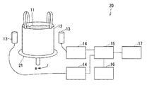
FIG. 4 is a configuration diagram showing a radioactivity inspection apparatus according to the second embodiment. In the second embodiment, the same parts as those in the first embodiment are denoted by the same reference numerals, and the description is simplified or omitted.
本第2実施形態の放射能検査装置20が第1実施形態と異なる点は、放射線検出器13が容器12の周方向に複数個(例えば2個)配置され、容器12を搭載するための回転台21により、容器12をその周方向に180°以下の所定ピッチで回転させることで、容器12の側面に対する放射線検出器13の相対位置が変更可能に構成された点である。また、複数の放射線検出器13のそれぞれの後段には放射線計数手段14が個別に設けられ、この複数の放射線計数手段14が単一の偏在パターン推定手段15に接続されている。
The
つまり、2台の放射線検出器13を対向位置(容器12の周方向反対位置)に配置させ、更に、回転台21により容器12を角度90°のピッチでe方向に回転させた場合、2回の検出動作で、図1の位置a〜dの4箇所での検出が可能になる。また、2台の放射線検出器13を容器12における周方向角度90°の位置に配置し、回転台21により容器12を角度180°のピッチでe方向に回転させた場合にも、同様に2回の検出動作で、図1の位置a〜dの4箇所での検出が可能になる。放射線検出器13を配置する容器12に対する配置角度は特に限定しないが、放射線検出器13の配置角度と回転台21の回転ピッチの組み合わせで得られる放射線検出器13の検出位置は、偏在パターン記憶手段16に記憶された推定用検出器応答パターンにおける放射能検出器13の検出位置と整合させておく。
That is, when two
上述の2台の放射線検出器13から出力された放射線信号(波高値パルス)は、後段の2台の放射線計数手段14でそれぞれ計数される。各放射線計数手段14は、接続された放射線検出器13の検出位置におけるγ線エネルギスペクトルを計測して、それぞれ、検出器応答パターンを部分的に演算する。更に偏在パターン推定手段15は、各放射線計数手段14で求めた検出器応答パターンを1つにまとめ、この1つにまとめた検出器応答パターンを、偏在パターン記憶手段16に記憶された放射能偏在パターンに対応する推定用検出器応答パターンと照合して、放射能偏在パターンを推定する。放射能偏在パターンの推定から放射能量の算出までは第1実施形態と同様である。
The radiation signals (crest value pulses) output from the two
以上のように構成されたことから、本第2実施形態においても、第1実施形態の効果(1)及び(2)と同様な効果を奏するほか、次の効果(3)を奏する。 With the configuration as described above, the second embodiment also provides the following effect (3) in addition to the same effects as the effects (1) and (2) of the first embodiment.
(3)放射線検出器13が容器12の周方向に複数台配置され、容器12を搭載するための回転台21により、容器12を周方向に所定ピッチで回転させることで、各放射線検出器13によるγ線の少ない検出回数で偏在パターン推定手段15が放射能偏在パターンを推定するので、廃棄物11が収納された容器12の放射能量を短時間に算出できる。
(3) A plurality of
以上、本発明のいくつかの実施形態を説明したが、これらの実施形態は、例として提示したものであり、発明の範囲を限定することは意図していない。これらの実施形態は、その他の様々な形態で実施されることが可能であり、発明の要旨を逸脱しない範囲で、種々の省略、置き換え、変更を行うことができ、また、それらの置き換えや変更は、発明の範囲や要旨に含まれると共に、特許請求の範囲に記載された発明とその均等の範囲に含まれる。 As mentioned above, although some embodiment of this invention was described, these embodiment is shown as an example and is not intending limiting the range of invention. These embodiments can be implemented in various other forms, and various omissions, replacements, and changes can be made without departing from the spirit of the invention. Is included in the scope and gist of the invention, and is included in the invention described in the claims and the equivalents thereof.
例えば、図5に示すように、放射線検出器13の位置aを、容器12に対し位置a1、a2のように容器12の高さ方向に変更し、放射線検出器13が各高さ位置で、容器12の周方向に相対移動してγ線を検出するようにしてもよい。
For example, as shown in FIG. 5, the position a of the
また、上述の両実施形態では、放射線計数手段14は、γ線エネルギスペクトルを計測可能な多重波高分析器の場合を述べたが、γ線エネルギスペクトルが単純なスペクトル形状でピーク領域と散乱領域を容易に区別できる場合には、2領域程度を弁別して計測可能なシングルチャネルアナライザを用いてもよい。 In both of the above-described embodiments, the radiation counting means 14 is a multi-wave height analyzer capable of measuring a γ-ray energy spectrum. However, the γ-ray energy spectrum has a simple spectral shape and has a peak region and a scattering region. If it can be easily distinguished, a single channel analyzer that can discriminate and measure about two regions may be used.
10 放射線検査装置
11 廃棄物(測定対象物)
12 容器
13 放射線検出器
14 放射線計数手段
15 偏在パターン推定手段
16 偏在パターン記憶手段
17 放射能算出手段
20 放射線検査装置
21 回転台
10 Radiation Inspection Equipment 11 Waste (Measurement Object)
12
Claims (8)
この放射線検出器が前記容器との複数の相対位置毎に出力した放射線信号を計数すると共に、この放射線計数値から検出器応答パターンを求める放射線計数手段と、
前記容器に収納された前記測定対象物の複数種類の放射能偏在パターン、及びこの複数種類の放射能偏在パターンのそれぞれに対応する複数種類の推定用検出器応答パターンを予め記憶する偏在パターン記憶手段と、
前記放射線計数手段で求めた検出器応答パターンと前記偏在パターン記憶手段に予め記憶された複数種類の推定用検出器応答パターンとを照合し、いずれかの推定用検出器応答パターンに対応する放射能偏在パターンを選択する偏在パターン推定手段と、
この偏在パターン推定手段にて選択された放射能偏在パターンに関連づけて設定された放射能換算係数を用いて、前記放射線計数手段にて計数された放射線計数値から前記容器の放射能量を算出する放射能算出手段と、を有することを特徴とする放射能検査装置。 A radiation detector capable of detecting radiation emitted from a measurement object stored in a container and outputting a radiation signal, and capable of changing a relative position with the container;
The radiation detector counts the radiation signal output for each of a plurality of relative positions with the container, and the radiation counting means obtains a detector response pattern from the radiation count value,
A plurality of types of radioactivity uneven distribution patterns of the measurement object stored in the container and a plurality of types of estimation detector response patterns corresponding to the plurality of types of radioactivity uneven distribution patterns are stored in advance. When,
The radioactivity corresponding to one of the estimation detector response patterns is obtained by collating the detector response pattern obtained by the radiation counting means with a plurality of types of estimation detector response patterns stored in advance in the uneven distribution pattern storage means. An uneven distribution pattern estimating means for selecting an uneven distribution pattern;
Radiation for calculating the radioactivity amount of the container from the radiation count value counted by the radiation counting means, using the radioactivity conversion coefficient set in association with the radioactivity uneven distribution pattern selected by the uneven distribution pattern estimating means A radioactivity inspection apparatus comprising:
放射線計数手段が求める検出器応答パターンと、偏在パターン記憶手段に記憶される推定用検出器応答パターンは、前記放射線検出器の対向する位置でのγ線エネルギスペクトルにおける光電ピーク計数率の比、前記放射線検出器の隣接する位置でのγ線エネルギスペクトルにおける光電ピーク計数率の比、前記放射線検出器のそれぞれの位置でのγ線エネルギスペクトルにおける光電ピーク計数率と散乱領域計数率との比、が組み合わされたものであることを特徴とする請求項1に記載の放射能検査装置。 The radiation detector is a γ-ray detector that detects γ-rays,
The detector response pattern obtained by the radiation counting means and the estimation detector response pattern stored in the uneven distribution pattern storage means are the ratio of the photoelectric peak count rate in the γ-ray energy spectrum at the opposite position of the radiation detector, The ratio of the photoelectric peak count rate in the γ-ray energy spectrum at the position adjacent to the radiation detector, the ratio of the photoelectric peak count rate and the scattering region count rate in the γ-ray energy spectrum at each position of the radiation detector, The radioactivity test apparatus according to claim 1, wherein the radioactivity test apparatus is combined.
放射線計数手段が求めた検出器応答パターンの個々の数値を前記推定用検出器応答パターンの個々の数値と照合して前記判定幅に入るときに、その推定用検出器応答パターンに対応する放射能偏在パターンを抽出し、
この抽出した放射能偏在パターンに対応する推定用検出器応答パターンの個々の数値と前記検出器応答パターンの個々の数値との差が最も小さくなるときに、この差が最も小さくなった推定用検出器応答パターンに対応する放射能偏在パターンを、放射能偏在パターンとして選択することを特徴とする請求項1または2に記載の放射能検査装置。 The uneven pattern estimation means has a predetermined determination width for each numerical value of the estimation detector response pattern corresponding to the radioactivity uneven distribution pattern stored in the uneven distribution pattern storage means,
When each numerical value of the detector response pattern obtained by the radiation counting means is compared with each numerical value of the estimation detector response pattern and enters the determination range, the radioactivity corresponding to the estimation detector response pattern Extract the uneven distribution pattern,
When the difference between the individual numerical value of the estimation detector response pattern corresponding to the extracted radioactivity uneven distribution pattern and the individual numerical value of the detector response pattern is the smallest, the detection for estimation in which the difference is the smallest The radioactivity inspection apparatus according to claim 1, wherein a radioactivity uneven distribution pattern corresponding to the vessel response pattern is selected as the radioactivity uneven distribution pattern.
この検出器応答パターンを用いて、前記容器に収納された前記測定対象物の放射能偏在パターンを推定し、
この放射能偏在パターンに関連づけて設定された放射能換算計数を用いて、前記放射線計数値から前記容器の放射能量を算出することを特徴とする放射能検査方法。 The radiation detector detects radiation at a plurality of positions around the container containing the measurement object that emits radiation, outputs a radiation signal, obtains a detector response pattern from the radiation count value obtained by counting the radiation signal,
Using this detector response pattern, estimate the radioactivity uneven distribution pattern of the measurement object stored in the container,
A radioactivity inspection method, wherein a radioactivity amount of the container is calculated from the radiation count value using a radioactivity conversion count set in association with the radioactivity uneven distribution pattern.
放射線計数値から求めた検出器応答パターンと前記推定用検出器応答パターンとを照合し、いずれかの推定用検出器応答パターンに対応する放射能偏在パターンを選択することで行うことを特徴とする請求項6に記載の放射能検査方法。 The estimation of the radioactivity uneven distribution pattern includes a plurality of types of radioactivity uneven distribution patterns of the measurement object stored in the container, and a plurality of types of estimation detector response patterns corresponding to the plurality of types of radioactivity uneven distribution patterns, respectively. Prepare memorized uneven distribution pattern storage means,
It is performed by collating a detector response pattern obtained from a radiation count value with the estimation detector response pattern and selecting a radioactivity uneven distribution pattern corresponding to any one of the estimation detector response patterns. The radioactivity test method according to claim 6.
放射線計数値から求める検出器応答パターン、及び偏在パターン記憶手段に記憶される推定用検出器応答パターンは、前記放射線検出器の対向する位置でのγ線エネルギスペクトルにおける光電ピーク計数率の比、前記放射線検出器の隣接する位置でのγ線エネルギスペクトルにおける光電ピーク計数率の比、前記放射線検出器のそれぞれの位置でのγ線エネルギスペクトルにおける光電ピーク計数率と散乱領域計数率との比、が組み合わされたものであることを特徴とする請求項6または7に記載の放射能検査方法。 The radiation detector is a gamma ray detector that detects gamma rays,
The detector response pattern obtained from the radiation count value and the detector response pattern for estimation stored in the uneven distribution pattern storage means are the ratio of the photoelectric peak count rate in the γ-ray energy spectrum at the opposite position of the radiation detector, The ratio of the photoelectric peak count rate in the γ-ray energy spectrum at the position adjacent to the radiation detector, the ratio of the photoelectric peak count rate and the scattering region count rate in the γ-ray energy spectrum at each position of the radiation detector, The radioactivity test method according to claim 6 or 7, wherein the radioactivity test method is combined.
Priority Applications (1)
| Application Number | Priority Date | Filing Date | Title |
|---|---|---|---|
| JP2013253246A JP6139391B2 (en) | 2013-12-06 | 2013-12-06 | Radioactivity inspection apparatus and method |
Applications Claiming Priority (1)
| Application Number | Priority Date | Filing Date | Title |
|---|---|---|---|
| JP2013253246A JP6139391B2 (en) | 2013-12-06 | 2013-12-06 | Radioactivity inspection apparatus and method |
Publications (2)
| Publication Number | Publication Date |
|---|---|
| JP2015111069A true JP2015111069A (en) | 2015-06-18 |
| JP6139391B2 JP6139391B2 (en) | 2017-05-31 |
Family
ID=53525993
Family Applications (1)
| Application Number | Title | Priority Date | Filing Date |
|---|---|---|---|
| JP2013253246A Expired - Fee Related JP6139391B2 (en) | 2013-12-06 | 2013-12-06 | Radioactivity inspection apparatus and method |
Country Status (1)
| Country | Link |
|---|---|
| JP (1) | JP6139391B2 (en) |
Cited By (1)
| Publication number | Priority date | Publication date | Assignee | Title |
|---|---|---|---|---|
| JP2021096072A (en) * | 2019-12-13 | 2021-06-24 | 株式会社アトックス | Radiation measuring device and radiation measuring method |
Citations (8)
| Publication number | Priority date | Publication date | Assignee | Title |
|---|---|---|---|---|
| JPH01257292A (en) * | 1987-12-29 | 1989-10-13 | Hitachi Ltd | Radioactivity measurement method and its device |
| JPH04235379A (en) * | 1991-01-09 | 1992-08-24 | Toshiba Corp | Measuring method of radioactivity |
| JP2001517304A (en) * | 1997-02-13 | 2001-10-02 | パッカード バイオサイエンス カンパニー | Calibration method for radiation spectroscopy |
| JP2005180936A (en) * | 2003-12-16 | 2005-07-07 | Mitsubishi Heavy Ind Ltd | Radioactive substance content measuring method and measuring apparatus |
| JP2008139094A (en) * | 2006-11-30 | 2008-06-19 | Toshiba Corp | Radioactivity measurement method and apparatus |
| WO2012131329A2 (en) * | 2011-03-31 | 2012-10-04 | Babcock Nulcear Limited | Improvements in and relating to methods and systems for investigating radioactive sources in locations |
| JP2013231611A (en) * | 2012-04-27 | 2013-11-14 | Fuji Electric Co Ltd | Height distribution measuring monitor |
| JP2015052565A (en) * | 2013-09-09 | 2015-03-19 | 株式会社テクノエックス | Radiation dose measuring device |
-
2013
- 2013-12-06 JP JP2013253246A patent/JP6139391B2/en not_active Expired - Fee Related
Patent Citations (8)
| Publication number | Priority date | Publication date | Assignee | Title |
|---|---|---|---|---|
| JPH01257292A (en) * | 1987-12-29 | 1989-10-13 | Hitachi Ltd | Radioactivity measurement method and its device |
| JPH04235379A (en) * | 1991-01-09 | 1992-08-24 | Toshiba Corp | Measuring method of radioactivity |
| JP2001517304A (en) * | 1997-02-13 | 2001-10-02 | パッカード バイオサイエンス カンパニー | Calibration method for radiation spectroscopy |
| JP2005180936A (en) * | 2003-12-16 | 2005-07-07 | Mitsubishi Heavy Ind Ltd | Radioactive substance content measuring method and measuring apparatus |
| JP2008139094A (en) * | 2006-11-30 | 2008-06-19 | Toshiba Corp | Radioactivity measurement method and apparatus |
| WO2012131329A2 (en) * | 2011-03-31 | 2012-10-04 | Babcock Nulcear Limited | Improvements in and relating to methods and systems for investigating radioactive sources in locations |
| JP2013231611A (en) * | 2012-04-27 | 2013-11-14 | Fuji Electric Co Ltd | Height distribution measuring monitor |
| JP2015052565A (en) * | 2013-09-09 | 2015-03-19 | 株式会社テクノエックス | Radiation dose measuring device |
Cited By (2)
| Publication number | Priority date | Publication date | Assignee | Title |
|---|---|---|---|---|
| JP2021096072A (en) * | 2019-12-13 | 2021-06-24 | 株式会社アトックス | Radiation measuring device and radiation measuring method |
| JP7320441B2 (en) | 2019-12-13 | 2023-08-03 | 株式会社アトックス | Radiation measuring device and radiation measuring method |
Also Published As
| Publication number | Publication date |
|---|---|
| JP6139391B2 (en) | 2017-05-31 |
Similar Documents
| Publication | Publication Date | Title |
|---|---|---|
| US10281595B2 (en) | Method and apparatus for distinguishing radionuclide by using plastic scintillator | |
| WO2004095060A3 (en) | X-ray imaging technique | |
| US20100010764A1 (en) | Correction of a radioactivity measurement using particles from atmospheric source | |
| JP5988890B2 (en) | Radioactivity analyzer and radioactivity analysis method | |
| JP2012127942A (en) | Apparatus and method for measuring positron annihilation characteristic | |
| CN112997102A (en) | Radiation detection system and method | |
| US11035963B2 (en) | Method for detecting radionuclide, process for detecting radionuclide using the same, and radiation detector for the same | |
| JP2017161259A (en) | Device and method for radioactive concentration measurement | |
| US10139498B2 (en) | Radiation measurement apparatus and method | |
| KR102249120B1 (en) | Analysis program and analysis system for radioactive contamination in and outside the body of the subject | |
| JP6139391B2 (en) | Radioactivity inspection apparatus and method | |
| JP2018179537A (en) | Radioactivity measuring device and radioactivity measuring method | |
| JP5450356B2 (en) | Radiation detection method | |
| CN201196635Y (en) | Integration system used for active material detection and X ray radiation imaging | |
| JP5926362B1 (en) | Radioactivity concentration measuring apparatus and radioactivity concentration measuring method | |
| JP2012242369A (en) | Radiation detector | |
| Kobayashi et al. | Characteristic X-ray detector: In-situ imaging of radioactive contaminant distributions | |
| JP6846800B2 (en) | Radioactivity measurement system and radioactivity measurement method | |
| JP2008122088A (en) | Radioactivity measuring device | |
| RU2578048C1 (en) | Device for radiation density measurement | |
| RU2586383C1 (en) | Device for neutron spectrometry | |
| CN101539557B (en) | Integrated system for radioactive material detection and X-ray imaging | |
| Liu et al. | Development of a high-resolution and omnidirectional field-of-view neutron imager | |
| RU119131U1 (en) | SCINTILLATION DETECTOR OF ELECTRONS AND BETA RADIATION | |
| CN102565097B (en) | Integration system for radioactive substance detection and X-ray radiation imaging |
Legal Events
| Date | Code | Title | Description |
|---|---|---|---|
| A621 | Written request for application examination |
Free format text: JAPANESE INTERMEDIATE CODE: A621 Effective date: 20160209 |
|
| A977 | Report on retrieval |
Free format text: JAPANESE INTERMEDIATE CODE: A971007 Effective date: 20161116 |
|
| A131 | Notification of reasons for refusal |
Free format text: JAPANESE INTERMEDIATE CODE: A131 Effective date: 20161122 |
|
| A521 | Request for written amendment filed |
Free format text: JAPANESE INTERMEDIATE CODE: A523 Effective date: 20161227 |
|
| TRDD | Decision of grant or rejection written | ||
| A01 | Written decision to grant a patent or to grant a registration (utility model) |
Free format text: JAPANESE INTERMEDIATE CODE: A01 Effective date: 20170404 |
|
| A61 | First payment of annual fees (during grant procedure) |
Free format text: JAPANESE INTERMEDIATE CODE: A61 Effective date: 20170427 |
|
| R151 | Written notification of patent or utility model registration |
Ref document number: 6139391 Country of ref document: JP Free format text: JAPANESE INTERMEDIATE CODE: R151 |
|
| LAPS | Cancellation because of no payment of annual fees |