JP2015113003A - Work vehicle - Google Patents
Work vehicle Download PDFInfo
- Publication number
- JP2015113003A JP2015113003A JP2013256333A JP2013256333A JP2015113003A JP 2015113003 A JP2015113003 A JP 2015113003A JP 2013256333 A JP2013256333 A JP 2013256333A JP 2013256333 A JP2013256333 A JP 2013256333A JP 2015113003 A JP2015113003 A JP 2015113003A
- Authority
- JP
- Japan
- Prior art keywords
- case
- top plate
- exhaust gas
- engine
- work vehicle
- Prior art date
- Legal status (The legal status is an assumption and is not a legal conclusion. Google has not performed a legal analysis and makes no representation as to the accuracy of the status listed.)
- Granted
Links
Images

Classifications
-
- B—PERFORMING OPERATIONS; TRANSPORTING
- B60—VEHICLES IN GENERAL
- B60K—ARRANGEMENT OR MOUNTING OF PROPULSION UNITS OR OF TRANSMISSIONS IN VEHICLES; ARRANGEMENT OR MOUNTING OF PLURAL DIVERSE PRIME-MOVERS IN VEHICLES; AUXILIARY DRIVES FOR VEHICLES; INSTRUMENTATION OR DASHBOARDS FOR VEHICLES; ARRANGEMENTS IN CONNECTION WITH COOLING, AIR INTAKE, GAS EXHAUST OR FUEL SUPPLY OF PROPULSION UNITS IN VEHICLES
- B60K13/00—Arrangement in connection with combustion air intake or gas exhaust of propulsion units
- B60K13/04—Arrangement in connection with combustion air intake or gas exhaust of propulsion units concerning exhaust
-
- A—HUMAN NECESSITIES
- A01—AGRICULTURE; FORESTRY; ANIMAL HUSBANDRY; HUNTING; TRAPPING; FISHING
- A01B—SOIL WORKING IN AGRICULTURE OR FORESTRY; PARTS, DETAILS, OR ACCESSORIES OF AGRICULTURAL MACHINES OR IMPLEMENTS, IN GENERAL
- A01B76/00—Parts, details or accessories of agricultural machines or implements, not provided for in groups A01B51/00 - A01B75/00
-
- E—FIXED CONSTRUCTIONS
- E02—HYDRAULIC ENGINEERING; FOUNDATIONS; SOIL SHIFTING
- E02F—DREDGING; SOIL-SHIFTING
- E02F9/00—Component parts of dredgers or soil-shifting machines, not restricted to one of the kinds covered by groups E02F3/00 - E02F7/00
- E02F9/08—Superstructures; Supports for superstructures
- E02F9/0858—Arrangement of component parts installed on superstructures not otherwise provided for, e.g. electric components, fenders, air-conditioning units
- E02F9/0866—Engine compartment, e.g. heat exchangers, exhaust filters, cooling devices, silencers, mufflers, position of hydraulic pumps in the engine compartment
-
- E—FIXED CONSTRUCTIONS
- E02—HYDRAULIC ENGINEERING; FOUNDATIONS; SOIL SHIFTING
- E02F—DREDGING; SOIL-SHIFTING
- E02F9/00—Component parts of dredgers or soil-shifting machines, not restricted to one of the kinds covered by groups E02F3/00 - E02F7/00
- E02F9/08—Superstructures; Supports for superstructures
- E02F9/0858—Arrangement of component parts installed on superstructures not otherwise provided for, e.g. electric components, fenders, air-conditioning units
- E02F9/0883—Tanks, e.g. oil tank, urea tank, fuel tank
-
- E—FIXED CONSTRUCTIONS
- E02—HYDRAULIC ENGINEERING; FOUNDATIONS; SOIL SHIFTING
- E02F—DREDGING; SOIL-SHIFTING
- E02F9/00—Component parts of dredgers or soil-shifting machines, not restricted to one of the kinds covered by groups E02F3/00 - E02F7/00
- E02F9/08—Superstructures; Supports for superstructures
- E02F9/0858—Arrangement of component parts installed on superstructures not otherwise provided for, e.g. electric components, fenders, air-conditioning units
- E02F9/0891—Lids or bonnets or doors or details thereof
-
- F—MECHANICAL ENGINEERING; LIGHTING; HEATING; WEAPONS; BLASTING
- F01—MACHINES OR ENGINES IN GENERAL; ENGINE PLANTS IN GENERAL; STEAM ENGINES
- F01N—GAS-FLOW SILENCERS OR EXHAUST APPARATUS FOR MACHINES OR ENGINES IN GENERAL; GAS-FLOW SILENCERS OR EXHAUST APPARATUS FOR INTERNAL-COMBUSTION ENGINES
- F01N13/00—Exhaust or silencing apparatus characterised by constructional features
- F01N13/008—Mounting or arrangement of exhaust sensors in or on exhaust apparatus
-
- F—MECHANICAL ENGINEERING; LIGHTING; HEATING; WEAPONS; BLASTING
- F01—MACHINES OR ENGINES IN GENERAL; ENGINE PLANTS IN GENERAL; STEAM ENGINES
- F01N—GAS-FLOW SILENCERS OR EXHAUST APPARATUS FOR MACHINES OR ENGINES IN GENERAL; GAS-FLOW SILENCERS OR EXHAUST APPARATUS FOR INTERNAL-COMBUSTION ENGINES
- F01N3/00—Exhaust or silencing apparatus having means for purifying, rendering innocuous, or otherwise treating exhaust
- F01N3/02—Exhaust or silencing apparatus having means for purifying, rendering innocuous, or otherwise treating exhaust for cooling, or for removing solid constituents of, exhaust
- F01N3/021—Exhaust or silencing apparatus having means for purifying, rendering innocuous, or otherwise treating exhaust for cooling, or for removing solid constituents of, exhaust by means of filters
-
- F—MECHANICAL ENGINEERING; LIGHTING; HEATING; WEAPONS; BLASTING
- F01—MACHINES OR ENGINES IN GENERAL; ENGINE PLANTS IN GENERAL; STEAM ENGINES
- F01N—GAS-FLOW SILENCERS OR EXHAUST APPARATUS FOR MACHINES OR ENGINES IN GENERAL; GAS-FLOW SILENCERS OR EXHAUST APPARATUS FOR INTERNAL-COMBUSTION ENGINES
- F01N3/00—Exhaust or silencing apparatus having means for purifying, rendering innocuous, or otherwise treating exhaust
- F01N3/02—Exhaust or silencing apparatus having means for purifying, rendering innocuous, or otherwise treating exhaust for cooling, or for removing solid constituents of, exhaust
- F01N3/021—Exhaust or silencing apparatus having means for purifying, rendering innocuous, or otherwise treating exhaust for cooling, or for removing solid constituents of, exhaust by means of filters
- F01N3/023—Exhaust or silencing apparatus having means for purifying, rendering innocuous, or otherwise treating exhaust for cooling, or for removing solid constituents of, exhaust by means of filters using means for regenerating the filters, e.g. by burning trapped particles
-
- F—MECHANICAL ENGINEERING; LIGHTING; HEATING; WEAPONS; BLASTING
- F01—MACHINES OR ENGINES IN GENERAL; ENGINE PLANTS IN GENERAL; STEAM ENGINES
- F01N—GAS-FLOW SILENCERS OR EXHAUST APPARATUS FOR MACHINES OR ENGINES IN GENERAL; GAS-FLOW SILENCERS OR EXHAUST APPARATUS FOR INTERNAL-COMBUSTION ENGINES
- F01N3/00—Exhaust or silencing apparatus having means for purifying, rendering innocuous, or otherwise treating exhaust
- F01N3/08—Exhaust or silencing apparatus having means for purifying, rendering innocuous, or otherwise treating exhaust for rendering innocuous
- F01N3/10—Exhaust or silencing apparatus having means for purifying, rendering innocuous, or otherwise treating exhaust for rendering innocuous by thermal or catalytic conversion of noxious components of exhaust
- F01N3/103—Oxidation catalysts for HC and CO only
-
- F—MECHANICAL ENGINEERING; LIGHTING; HEATING; WEAPONS; BLASTING
- F01—MACHINES OR ENGINES IN GENERAL; ENGINE PLANTS IN GENERAL; STEAM ENGINES
- F01N—GAS-FLOW SILENCERS OR EXHAUST APPARATUS FOR MACHINES OR ENGINES IN GENERAL; GAS-FLOW SILENCERS OR EXHAUST APPARATUS FOR INTERNAL-COMBUSTION ENGINES
- F01N3/00—Exhaust or silencing apparatus having means for purifying, rendering innocuous, or otherwise treating exhaust
- F01N3/08—Exhaust or silencing apparatus having means for purifying, rendering innocuous, or otherwise treating exhaust for rendering innocuous
- F01N3/10—Exhaust or silencing apparatus having means for purifying, rendering innocuous, or otherwise treating exhaust for rendering innocuous by thermal or catalytic conversion of noxious components of exhaust
- F01N3/18—Exhaust or silencing apparatus having means for purifying, rendering innocuous, or otherwise treating exhaust for rendering innocuous by thermal or catalytic conversion of noxious components of exhaust characterised by methods of operation; Control
- F01N3/20—Exhaust or silencing apparatus having means for purifying, rendering innocuous, or otherwise treating exhaust for rendering innocuous by thermal or catalytic conversion of noxious components of exhaust characterised by methods of operation; Control specially adapted for catalytic conversion
- F01N3/206—Adding periodically or continuously substances to exhaust gases for promoting purification, e.g. catalytic material in liquid form, NOx reducing agents
- F01N3/2066—Selective catalytic reduction [SCR]
-
- B—PERFORMING OPERATIONS; TRANSPORTING
- B60—VEHICLES IN GENERAL
- B60Y—INDEXING SCHEME RELATING TO ASPECTS CROSS-CUTTING VEHICLE TECHNOLOGY
- B60Y2200/00—Type of vehicle
- B60Y2200/20—Off-Road Vehicles
- B60Y2200/22—Agricultural vehicles
- B60Y2200/221—Tractors
-
- F—MECHANICAL ENGINEERING; LIGHTING; HEATING; WEAPONS; BLASTING
- F01—MACHINES OR ENGINES IN GENERAL; ENGINE PLANTS IN GENERAL; STEAM ENGINES
- F01N—GAS-FLOW SILENCERS OR EXHAUST APPARATUS FOR MACHINES OR ENGINES IN GENERAL; GAS-FLOW SILENCERS OR EXHAUST APPARATUS FOR INTERNAL-COMBUSTION ENGINES
- F01N2470/00—Structure or shape of exhaust gas passages, pipes or tubes
-
- F—MECHANICAL ENGINEERING; LIGHTING; HEATING; WEAPONS; BLASTING
- F01—MACHINES OR ENGINES IN GENERAL; ENGINE PLANTS IN GENERAL; STEAM ENGINES
- F01N—GAS-FLOW SILENCERS OR EXHAUST APPARATUS FOR MACHINES OR ENGINES IN GENERAL; GAS-FLOW SILENCERS OR EXHAUST APPARATUS FOR INTERNAL-COMBUSTION ENGINES
- F01N2470/00—Structure or shape of exhaust gas passages, pipes or tubes
- F01N2470/14—Plurality of outlet tubes, e.g. in parallel or with different length
-
- F—MECHANICAL ENGINEERING; LIGHTING; HEATING; WEAPONS; BLASTING
- F01—MACHINES OR ENGINES IN GENERAL; ENGINE PLANTS IN GENERAL; STEAM ENGINES
- F01N—GAS-FLOW SILENCERS OR EXHAUST APPARATUS FOR MACHINES OR ENGINES IN GENERAL; GAS-FLOW SILENCERS OR EXHAUST APPARATUS FOR INTERNAL-COMBUSTION ENGINES
- F01N2610/00—Adding substances to exhaust gases
- F01N2610/02—Adding substances to exhaust gases the substance being ammonia or urea
-
- F—MECHANICAL ENGINEERING; LIGHTING; HEATING; WEAPONS; BLASTING
- F01—MACHINES OR ENGINES IN GENERAL; ENGINE PLANTS IN GENERAL; STEAM ENGINES
- F01N—GAS-FLOW SILENCERS OR EXHAUST APPARATUS FOR MACHINES OR ENGINES IN GENERAL; GAS-FLOW SILENCERS OR EXHAUST APPARATUS FOR INTERNAL-COMBUSTION ENGINES
- F01N2610/00—Adding substances to exhaust gases
- F01N2610/14—Arrangements for the supply of substances, e.g. conduits
- F01N2610/1406—Storage means for substances, e.g. tanks or reservoirs
-
- F—MECHANICAL ENGINEERING; LIGHTING; HEATING; WEAPONS; BLASTING
- F01—MACHINES OR ENGINES IN GENERAL; ENGINE PLANTS IN GENERAL; STEAM ENGINES
- F01N—GAS-FLOW SILENCERS OR EXHAUST APPARATUS FOR MACHINES OR ENGINES IN GENERAL; GAS-FLOW SILENCERS OR EXHAUST APPARATUS FOR INTERNAL-COMBUSTION ENGINES
- F01N3/00—Exhaust or silencing apparatus having means for purifying, rendering innocuous, or otherwise treating exhaust
- F01N3/08—Exhaust or silencing apparatus having means for purifying, rendering innocuous, or otherwise treating exhaust for rendering innocuous
- F01N3/10—Exhaust or silencing apparatus having means for purifying, rendering innocuous, or otherwise treating exhaust for rendering innocuous by thermal or catalytic conversion of noxious components of exhaust
- F01N3/18—Exhaust or silencing apparatus having means for purifying, rendering innocuous, or otherwise treating exhaust for rendering innocuous by thermal or catalytic conversion of noxious components of exhaust characterised by methods of operation; Control
- F01N3/20—Exhaust or silencing apparatus having means for purifying, rendering innocuous, or otherwise treating exhaust for rendering innocuous by thermal or catalytic conversion of noxious components of exhaust characterised by methods of operation; Control specially adapted for catalytic conversion
- F01N3/206—Adding periodically or continuously substances to exhaust gases for promoting purification, e.g. catalytic material in liquid form, NOx reducing agents
-
- Y—GENERAL TAGGING OF NEW TECHNOLOGICAL DEVELOPMENTS; GENERAL TAGGING OF CROSS-SECTIONAL TECHNOLOGIES SPANNING OVER SEVERAL SECTIONS OF THE IPC; TECHNICAL SUBJECTS COVERED BY FORMER USPC CROSS-REFERENCE ART COLLECTIONS [XRACs] AND DIGESTS
- Y02—TECHNOLOGIES OR APPLICATIONS FOR MITIGATION OR ADAPTATION AGAINST CLIMATE CHANGE
- Y02A—TECHNOLOGIES FOR ADAPTATION TO CLIMATE CHANGE
- Y02A50/00—TECHNOLOGIES FOR ADAPTATION TO CLIMATE CHANGE in human health protection, e.g. against extreme weather
- Y02A50/20—Air quality improvement or preservation, e.g. vehicle emission control or emission reduction by using catalytic converters
Landscapes
- Engineering & Computer Science (AREA)
- Chemical & Material Sciences (AREA)
- General Engineering & Computer Science (AREA)
- Mechanical Engineering (AREA)
- Combustion & Propulsion (AREA)
- Mining & Mineral Resources (AREA)
- Civil Engineering (AREA)
- Structural Engineering (AREA)
- Chemical Kinetics & Catalysis (AREA)
- Health & Medical Sciences (AREA)
- Toxicology (AREA)
- Transportation (AREA)
- Analytical Chemistry (AREA)
- Materials Engineering (AREA)
- Life Sciences & Earth Sciences (AREA)
- Soil Sciences (AREA)
- Environmental Sciences (AREA)
- Exhaust Gas After Treatment (AREA)
- Component Parts Of Construction Machinery (AREA)
- Superstructure Of Vehicle (AREA)
- Cooling, Air Intake And Gas Exhaust, And Fuel Tank Arrangements In Propulsion Units (AREA)
Abstract
Description
本願発明は、エンジンを搭載した農業機械(トラクタ、コンバイン)または建設機械(ブルドーザ、油圧ショベル、ローダー)などの作業車両に係り、より詳しくは、排気ガス中に含まれた粒子状物質(すす、パティキュレート)、または排気ガス中に含まれた窒素酸化物質(NOx)等を除去する排気ガス浄化装置が設置されたトラクタなどの作業車両に関するものである。 The present invention relates to a work vehicle such as an agricultural machine (tractor, combine) or a construction machine (bulldozer, hydraulic excavator, loader) equipped with an engine, and more specifically, particulate matter (soot, contained in exhaust gas). The present invention relates to a work vehicle such as a tractor provided with an exhaust gas purifying device for removing particulate oxide or nitrogen oxides (NOx) contained in the exhaust gas.
トラクタまたはホイルローダ等の作業車両においては、走行機体の前部に配置されたエンジンのメンテナンス作業の能率化のため、エンジンを覆うためのボンネットの後部に開閉支点軸を配置し、その開閉支点軸回りにボンネットを回動させていた。また、従来から、ディーゼルエンジンの排気経路中に、排気ガス浄化装置(排気ガス後処理装置)として、ディーゼルパティキュレートフィルタを内設したフィルタケースと、尿素選択還元型触媒を内設した触媒ケースを設け、フィルタケースと触媒ケースに排気ガスを導入して、ディーゼルエンジンから排出された排気ガスを浄化処理する技術が知られている(例えば特許文献1または2参照)。 In a work vehicle such as a tractor or wheel loader, an opening / closing fulcrum shaft is arranged at the rear of the bonnet for covering the engine in order to improve the efficiency of maintenance work of the engine arranged at the front of the traveling machine body. The bonnet was rotated. Conventionally, a filter case having a diesel particulate filter and a catalyst case having a urea selective reduction catalyst are provided as exhaust gas purifiers (exhaust gas aftertreatment devices) in the exhaust path of a diesel engine. There has been known a technique for purifying exhaust gas discharged from a diesel engine by providing exhaust gas into a filter case and a catalyst case (see, for example, Patent Document 1 or 2).
例えば、エンジンの上部にフィルタケースまたは触媒ケースを組付ける場合、エンジンを冷却する必要がある反面、フィルタケースまたは触媒ケースの排気ガス温度を確保する必要があるから、エンジン上部周辺の温度が高温になりやすく、ボンネットなどが不適正に加熱される等の問題がある。また、フィルタケースまたは触媒ケースの排気ガスの圧力または温度を検出するセンサを設ける場合、フィルタケースまたは触媒ケースの近くに前記センサまたはハーネスを組込む構造では、前記センサまたはハーネスが排熱にて損傷しやすく、前記センサまたはハーネスなどの耐久性を向上できない等の問題がある。加えて、特許文献2のように、エンジンに対して離間させて触媒ケースを組付ける場合、エンジンから触媒ケースに排気ガスを供給する排気管が、走行機体に触媒ケースを支持させる支持部材にて形成されているから、特別な構造に支持部材を形成する必要があり、製造コストを容易に低減できない等の問題もある。
For example, when assembling a filter case or catalyst case at the top of the engine, it is necessary to cool the engine, but it is necessary to secure the exhaust gas temperature of the filter case or catalyst case. There is a problem that the bonnet is heated improperly. In addition, when a sensor for detecting the pressure or temperature of the exhaust gas in the filter case or the catalyst case is provided, in the structure in which the sensor or harness is incorporated near the filter case or the catalyst case, the sensor or harness is damaged by exhaust heat. There is a problem that durability of the sensor or the harness cannot be improved. In addition, when the catalyst case is assembled apart from the engine as in
そこで、本願発明は、これらの現状を検討して改善を施した作業車両を提供しようとするものである。 Therefore, the present invention seeks to provide a work vehicle that has been improved by examining these current conditions.
前記目的を達成するため、請求項1に係る発明の作業車両は、オペレータが搭乗する運転部と、エンジンの排気ガス中の粒子状物質を除去する第1ケースと、前記エンジンの排気ガス中の窒素酸化物質を除去する第2ケースを備える作業車両において、前記エンジンの上面側を覆うボンネットを備える構造であって、前記エンジンの上面側に配置する前記第1ケースまたは前記第2ケースの一方または両方に対向する前記ボンネットの天板部を、外側天板と内側天板にて二重構造に形成したものである。 In order to achieve the above object, a work vehicle according to a first aspect of the present invention includes a driving unit on which an operator is boarded, a first case for removing particulate matter in engine exhaust gas, and an engine exhaust gas in engine exhaust gas. In a work vehicle including a second case for removing nitrogen oxides, the work vehicle includes a bonnet that covers an upper surface side of the engine, and one of the first case and the second case disposed on the upper surface side of the engine or The top plate portion of the bonnet facing both is formed in a double structure with an outer top plate and an inner top plate.
請求項2に記載の発明は、請求項1に記載の作業車両において、前記第1ケースまたは前記第2ケースの排気ガス圧力または排気ガス温度を検出する排気差圧センサまたは排気温度センサと、前記排気差圧センサまたはハーネスコネクタを支持するセンサブラケットを備える構造であって、前記外側天板と内側天板間の遮熱空間にセンサブラケットを介して前記センサまたはハーネスコネクタを配置したものである。 According to a second aspect of the present invention, in the work vehicle according to the first aspect, an exhaust differential pressure sensor or an exhaust temperature sensor that detects an exhaust gas pressure or an exhaust gas temperature of the first case or the second case; The structure includes a sensor bracket that supports an exhaust differential pressure sensor or a harness connector, and the sensor or harness connector is disposed in a heat shield space between the outer top plate and the inner top plate via the sensor bracket.
請求項3に記載の発明は、請求項1に記載の作業車両において、前記運転部側の走行機体に立設させる後側フレームに前後連結フレームの後端側を連結させ、ラジエータ側の走行機体に立設させる前側フレームに前後連結フレームの前端側を連結させると共に、前記後側フレームに開閉支点軸を介してボンネットを支持させる構造であって、前記後側フレームに開閉支点軸を介してボンネット支持枠体を設け、前記ボンネット支持枠体に前記外側天板と内側天板を架設したものである。 According to a third aspect of the present invention, in the work vehicle according to the first aspect, the rear end side of the front / rear connecting frame is connected to the rear frame that is erected on the driving unit body on the driving unit side, and the radiator side traveling unit body is connected. The front frame of the front and rear connecting frame is connected to the front frame that is erected on the rear frame, and the hood is supported on the rear frame via an opening / closing fulcrum shaft, and the bonnet is connected to the rear frame via the opening / closing fulcrum shaft. A support frame is provided, and the outer top plate and the inner top plate are constructed on the bonnet support frame.
請求項4に記載の発明は、請求項1に記載の作業車両において、前記第1ケースに第2ケースを接続する尿素混合管と、尿素混合管に尿素水を供給する尿素水タンクを備える構造であって、前記内側天板の下面側に近接させて、前記第1ケースと前記第2ケースと前記尿素混合管を配置させると共に、前記エンジンが搭載される走行機体のうち、前記運転部下側の走行機体に前記尿素水タンクを配置したものである。 According to a fourth aspect of the present invention, in the work vehicle according to the first aspect, a structure is provided that includes a urea mixing pipe that connects the second case to the first case, and a urea water tank that supplies urea water to the urea mixing pipe. The first case, the second case, and the urea mixing pipe are arranged close to the lower surface side of the inner top plate, and the driving unit lower side of the traveling machine body on which the engine is mounted. The urea water tank is arranged on the traveling machine body.
請求項1に係る発明によれば、オペレータが搭乗する運転部と、エンジンの排気ガス中の粒子状物質を除去する第1ケースと、前記エンジンの排気ガス中の窒素酸化物質を除去する第2ケースを備える作業車両において、前記エンジンの上面側を覆うボンネットを備える構造であって、前記エンジンの上面側に配置する前記第1ケースまたは前記第2ケースの一方または両方に対向する前記ボンネットの天板部を、外側天板と内側天板にて二重構造に形成したものであるから、ボンネットなどが不適正に加熱されるのを容易に防止できるものでありながら、前記第1ケースまたは前記第2ケースの保温性などを簡単に向上できる。加えて、前記外側天板と内側天板の間に、差圧センサなどを設置可能な遮熱空間を簡単に形成できる。 According to the first aspect of the present invention, the operating unit on which the operator is boarded, the first case for removing particulate matter in the exhaust gas of the engine, and the second for removing nitrogen oxides in the exhaust gas of the engine. A work vehicle including a case, comprising a bonnet that covers an upper surface side of the engine, the top of the bonnet facing one or both of the first case and the second case disposed on the upper surface side of the engine. Since the plate portion is formed in a double structure with the outer top plate and the inner top plate, the bonnet and the like can be easily prevented from being improperly heated. The heat retaining property of the second case can be easily improved. In addition, a heat shield space in which a differential pressure sensor or the like can be installed can be easily formed between the outer top plate and the inner top plate.
請求項2に記載の発明によれば、前記第1ケースまたは前記第2ケースの排気ガス圧力または排気ガス温度を検出する排気差圧センサまたは排気温度センサと、前記排気差圧センサまたはハーネスコネクタを支持するセンサブラケットを備える構造であって、前記外側天板と内側天板間の遮熱空間にセンサブラケットを介して前記センサまたはハーネスコネクタを配置したものであるから、前記センサまたはハーネスに前記エンジンまたは各ケースの排熱が影響するのを容易に低減でき、前記センサまたはハーネスなどの耐久性を向上できる。 According to the second aspect of the present invention, the exhaust differential pressure sensor or the exhaust temperature sensor for detecting the exhaust gas pressure or the exhaust gas temperature of the first case or the second case, and the exhaust differential pressure sensor or the harness connector are provided. A structure including a sensor bracket for supporting, wherein the sensor or harness connector is disposed via a sensor bracket in a heat shield space between the outer top plate and the inner top plate, and the engine is installed in the sensor or harness. Or it can reduce easily that the exhaust heat of each case influences, and durability, such as the said sensor or a harness, can be improved.
請求項3に記載の発明によれば、前記運転部側の走行機体に立設させる後側フレームに前後連結フレームの後端側を連結させ、ラジエータ側の走行機体に立設させる前側フレームに前後連結フレームの前端側を連結させると共に、前記後側フレームに開閉支点軸を介してボンネットを支持させる構造であって、前記後側フレームに開閉支点軸を介してボンネット支持枠体を設け、前記ボンネット支持枠体に前記外側天板と内側天板を架設したものであるから、前記ボンネット支持枠体と後側フレームを介して前記外側天板と内側天板を高剛性に設置できる一方、耐熱性に乏しいが加工しやすい樹脂成型材料にて前記外側天板を形成でき、外観形状を向上できると共に、シンプルな板金形状の耐熱性材料にて前記内側天板を形成でき、ボンネットの耐熱性を向上できる。 According to the third aspect of the present invention, the rear end side of the front-rear connecting frame is connected to the rear frame that is erected on the traveling unit body on the driving unit side, and the front frame is front and rear that is erected on the radiator side traveling unit body. The front end side of the connecting frame is connected, and the bonnet is supported on the rear frame via an opening / closing fulcrum shaft, and a bonnet support frame is provided on the rear frame via the opening / closing fulcrum shaft. Since the outer top plate and the inner top plate are installed on the support frame, the outer top plate and the inner top plate can be installed with high rigidity via the bonnet support frame and the rear frame, while being heat resistant. The outer top plate can be formed from a resin molding material that is poor but easy to process, and the appearance can be improved, and the inner top plate can be formed from a simple sheet metal heat-resistant material. It can be improved in heat resistance.
請求項4に記載の発明によれば、前記第1ケースに第2ケースを接続する尿素混合管と、尿素混合管に尿素水を供給する尿素水タンクを備える構造であって、前記内側天板の下面側に近接させて、前記第1ケースと前記第2ケースと前記尿素混合管を配置させると共に、前記エンジンが搭載される走行機体のうち、前記運転部下側の走行機体に前記尿素水タンクを配置したものであるから、前記第1ケースと、前記第2ケースと、前記尿素混合管を、前記エンジンの上面側にコンパクトに支持できる。 According to a fourth aspect of the present invention, there is provided a urea mixing pipe that connects the second case to the first case, and a urea water tank that supplies urea water to the urea mixing pipe, and the inner top plate The first case, the second case, and the urea mixing pipe are arranged close to the lower surface side of the vehicle, and the urea water tank is disposed on the traveling machine body below the driving unit among the traveling machine bodies on which the engine is mounted. Therefore, the first case, the second case, and the urea mixing pipe can be compactly supported on the upper surface side of the engine.
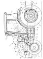
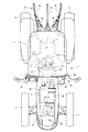
以下に、本発明を具体化した第1実施形態を図面(図1〜図6)に基づいて説明する。先ず、図1〜図5を参照して、ディーゼルエンジンを搭載した農作業用トラクタ1について説明する。図1〜図5に示す作業車両としての農作業用トラクタ1は、図示しない耕耘作業機などを装着して、圃場を耕す耕耘作業などを行うように構成されている。なお、以下の説明では、トラクタ1の前進方向に向かって左側を単に左側と称し、同じく前進方向に向かって右側を単に右側と称する。 Below, 1st Embodiment which actualized this invention is described based on drawing (FIGS. 1-6). First, a farm tractor 1 equipped with a diesel engine will be described with reference to FIGS. A farm tractor 1 as a work vehicle shown in FIGS. 1 to 5 is configured to perform a tilling work and the like for plowing a farm field by mounting a tillage working machine (not shown). In the following description, the left side in the forward direction of the tractor 1 is simply referred to as the left side, and the right side in the forward direction is also simply referred to as the right side.
図1〜図5に示す如く、作業車両としての農作業用トラクタ1は、走行機体2を左右一対の前車輪3と左右一対の後車輪4とで支持し、走行機体2の前部にディーゼルエンジン5を搭載し、ディーゼルエンジン5にて後車輪4及び前車輪3を駆動することにより、前後進走行するように構成されている。ディーゼルエンジン5の上面側及び左右側面側は、開閉可能なボンネット6にて覆われている。
As shown in FIGS. 1 to 5, a farm tractor 1 as a work vehicle supports a
また、走行機体2の上面のうち、ボンネット6の後方には、オペレータが搭乗する運転部としての運転キャビン7が設置されている。該キャビン7の内部には、オペレータが着座する操縦座席8と、操向手段としての操縦ハンドル9などを備えるフロントコラム10が設けられている。また、キャビン7底部の搭乗ステップ11外側方には左右の乗降ステップ12が設けられている。なお、フロントコラム10には、操縦機器として、左右のブレーキペダル13、クラッチペダル14、変速ペダル15、前後進切換レバー16などが配置されている。
In addition, on the upper surface of the
また、走行機体2は、ディーゼルエンジン5からの出力を変速して後車輪4(前車輪3)に伝達するためのミッションケース17を備える。ミッションケース17の後部には、左右のロワーリンク18、及びトップリンク19、及び左右のリフトアーム20などの牽引機構21を介して、図示しない耕耘作業機などが昇降動可能に連結され、ミッションケース17の後側面に設けるPTO軸22にて、前記耕耘作業機などを駆動するように構成する。さらに、トラクタ1の走行機体2は、ディーゼルエンジン5と、ミッションケース17と、それらを連結するクラッチケース23と、ディーゼルエンジン5から前方に向けて延設するフロントシャーシ24などにて構成される。
The
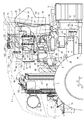
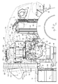
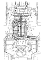
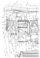
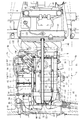
次に、図3〜図5を参照しながら、ディーゼルエンジン5と排気ガス排出構造について説明する。図3〜図5に示す如く、ディーゼルエンジン5のシリンダヘッド32の一側面には吸気マニホールド33が配置されている。シリンダヘッド32は、図示しないエンジン出力軸(クランク軸)とピストンが内蔵されたシリンダブロック35に上載されている。シリンダヘッド32の他側面に排気マニホールド36を配置している。
Next, the
図3〜図5に示す如く、エンジンの後面にフライホイールハウジング38を介してクラッチケース23前端側を固着している。さらに、シリンダブロック35の下面にオイルパン39を配置すると共に、シリンダブロック35の前面側に冷却ファン40を配置し、冷却ファン40に対向させてラジエータ41を設置する。ラジエータ41前方のフロントシャーシ23上に、オイルクーラ42、エアクリーナ43、バッテリ44などを配置している。また、ミッションケース17から前車輪3に向けてディーゼルエンジン5の動力を取出す前輪駆動軸46が、クラッチケース23の下方側に配置されている。
As shown in FIGS. 3 to 5, the front end side of the
図4に示すように、吸気マニホールド33には、再循環用の排気ガスを取込む排気ガス再循環装置(EGR)47を配置する。排気ガス再循環装置47を介してエアクリーナ43が吸気マニホールド33に接続される。エアクリーナ43にて除塵・浄化された外部空気は、吸気マニホールド33に送られ、ディーゼルエンジン5の各気筒に供給されるように構成している。
As shown in FIG. 4, an exhaust gas recirculation device (EGR) 47 that takes in exhaust gas for recirculation is disposed in the
上記の構成により、ディーゼルエンジン5から排気マニホールド36に排出された排気ガスの一部が、排気ガス再循環装置47を介して、吸気マニホールド33からディーゼルエンジン5の各気筒に還流されることによって、ディーゼルエンジン5の燃焼温度が下がり、ディーゼルエンジン5からの窒素酸化物(NOx)の排出量が低減され、かつディーゼルエンジン5の燃費が向上される。
With the above configuration, a part of the exhaust gas discharged from the
なお、冷却ファン40風にてディーゼルエンジン5を冷却するように構成している。また、図4に示す如く、ディーゼルエンジン5の4気筒分の各インジェクタ(図示省略)に、燃料タンク45を接続する燃料ポンプ52とコモンレール53を備える。シリンダヘッド32の吸気マニホールド33設置側にコモンレール53と燃料フィルタ54を配置し、吸気マニホールド33下方のシリンダブロック35に燃料ポンプ52を配置している。また、搭乗ステップ11の下面側のうち、クラッチケース23の左右側方に左右の燃料タンク45を搭載している。
The
なお、高圧の燃料がコモンレール53内に一時貯留され、コモンレール53内の高圧燃料がディーゼルエンジン5の各気筒(シリンダ)内部に供給されるものであり、前記各インジェクタの燃料噴射バルブがそれぞれ開閉制御されることによって、コモンレール53内の高圧の燃料がディーゼルエンジン5の各気筒に噴射される。即ち、前記各インジェクタの燃料噴射バルブを電子制御することによって、燃料の噴射圧力、噴射時期、噴射期間(噴射量)を高精度にコントロールできる。したがって、ディーゼルエンジン5から排出される窒素酸化物(NOx)を低減できる。
The high-pressure fuel is temporarily stored in the
図3〜図5に示す如く、前記ディーゼルエンジン5の各気筒から排出された排気ガスを浄化するための排気ガス浄化装置61として、ディーゼルエンジン5の排気ガス中の粒子状物質を除去するディーゼルパティキュレートフィルタ(DPF)としての第1ケース62と、ディーゼルエンジン5の排気ガス中の窒素酸化物質を除去する尿素選択触媒還元(SCR)システムとしての第2ケース63を備える。図5に示すように、第1ケース62には、酸化触媒64、スートフィルタ65が内設される。第2ケース63には、尿素選択触媒還元用のSCR触媒66、酸化触媒67が内設される。
As shown in FIGS. 3 to 5, as an exhaust
ディーゼルエンジン5の各気筒から排気マニホールド36に排出された排気ガスは、排気ガス浄化装置61等を経由して、外部に放出される。排気ガス浄化装置61によって、ディーゼルエンジン5の排気ガス中の一酸化炭素(CO)や、炭化水素(HC)や、粒子状物質(PM)や、窒素酸化物質(NOx)を低減するように構成している。
Exhaust gas discharged from each cylinder of the
第1ケース62は、平面視でディーゼルエンジン5の出力軸(クランク軸)と平行な方向(機体前後方向)に長く延びた横長の長尺円筒形状に構成している。第1ケース62の筒形状一端側に、排気ガスを取入れるDPF入口管68を設ける。ディーゼルエンジン5の前後面のうち、シリンダヘッド32の前後面に、前支脚体69及び後支脚体70を介して支持テーブル体71の前後部を連結させ、支持テーブル体71の上面側に第1ケース62と第2ケース63を載置している。即ち、前支脚体69及び後支脚体70を介して、ディーゼルエンジン5の上面側に支持テーブル体71を取付ける。ディーゼルエンジン5の前後方向に、円筒状の第1ケース62と第2ケース63の長手方向を向けて、排気マニホールド36と平行に第1ケース62と第2ケース63を支持させる。
The
また、ディーゼルエンジン5に空気を強制的に送り込む過給機48を介して、排気マニホールド36の排気ガス出口にDPF入口管68を連通させ、DPF入口管68から第1ケース62内にディーゼルエンジン5の排気ガスを導入する。一方、第1ケース62の筒形状他端側に、排気ガスを排出するDPF出口管72を設ける。第1ケース62のDPF出口管72に尿素混合管73の入口側を接続させ、尿素混合管73内に第1ケース28の排気ガスを導入するように構成している。
Further, a
また、第2ケース63の両側(排気ガス移動方向一端側と同他端側)には、排気ガスを取入れるSCR入口管136と、排気ガスを排出するSCR出口管137を設けている。DPF出口管72に尿素混合管73を介してSCR入口管136を接続させ、第1ケース62の排気ガスを第2ケース63内に導入するように構成している。加えて、DPF出口管135と、尿素混合管73は、ボルト締結させるDPF出口側フランジ体141にて着脱可能に接続されている。
In addition, an
さらに、SCR入口管136と、尿素混合管73は、SCR入口側フランジ体140にて着脱可能に接続されている。SCR入口側フランジ体140とDPF出口側フランジ体141を介して、第1ケース28と第2ケース29と尿素混合管39を一体的に結合させる。そして、第1ケース28と第2ケース29の各上面側に各2本の締結バンド84,85を半巻き状にそれぞれ装着して、支持テーブル体71に各締結バンド84,85の下端側をボルト締結している。
Furthermore, the
一方、図1、図2、図5に示す如く、運転キャビン7の前面のうち、運転キャビン7右側角隅部の前面にテールパイプ81を立設させ、ボンネット56内部に向けてテールパイプ81の下端側を延設させ、SCR出口管137に蛇腹管状可とう管82を介してテールパイプ81の下端側を接続し、第2ケース63にて浄化された排気ガスがテールパイプ81から運転キャビン7の上方に向けて排出される。可とう管82の接続にて、ディーゼルエンジン1側からテールパイプ81側に伝達される機械振動が低減される。また、運転キャビン7の前面のうち、テールパイプ81が配置された右側部と反対側のボンネット6の左側部に尿素水タンク91を設置している。即ち、ボンネット6後部の右側部にテールパイプ81を配置させる一方、ボンネット6後部の左側部に尿素水タンク91を振分けて配置している。
On the other hand, as shown in FIGS. 1, 2, and 5, a
さらに、ボンネット6左側後部の走行機体2(運転キャビン7の底部フレーム等)に尿素水タンク91を搭載する。キャビン7左側の前面下部に、燃料タンク45の注油口92と、尿素水タンク71の注水口93を隣接させて設ける。オペレータの乗降頻度が低い運転キャビン7右側の前面にテールパイプ81が配置される一方、オペレータの乗降頻度が高い運転キャビン7左側の前面に注油口92と注水口93が配置される。なお、運転キャビン7は、左側または右側のいずれからでもオペレータが操縦座席8に乗降可能に構成されている。
Furthermore, a
また、図3、図5に示す如く、尿素水タンク91内の尿素水溶液を圧送する尿素水噴射ポンプ94と、尿素水噴射ポンプ94を駆動する電動モータ95と、尿素水噴射ポンプ94に尿素水噴射管96を介して接続させる尿素水噴射ノズル97を備える。尿素混合管39に噴射台座77を介して尿素水噴射ノズル76を取付け、尿素混合管39の内部に尿素水噴射ノズル76から尿素水溶液を噴霧する。
3 and 5, a urea
即ち、第1ケース62内の酸化触媒64及びスートフィルタ65にて、ディーゼルエンジン5の排気ガス中の一酸化炭素(CO)や、炭化水素(HC)が低減される。次いで、尿素混合管73の内部で、ディーゼルエンジン5からの排気ガスに、尿素水噴射ノズル97からの尿素水が混合される。そして、第2ケース63内のSCR触媒66、酸化触媒67にて、尿素水がアンモニアとして混合された排気ガス中の窒素酸化物質(NOx)が低減され、テールパイプ81から機外に放出される。
That is, carbon monoxide (CO) and hydrocarbons (HC) in the exhaust gas of the
さらに、第1ケース62は、スートフィルタ65の粒子状物質の堆積状況を検出する差圧センサ111と、第1ケース62の排気ガス取入れ側の排気温度を検出する上流側ガス温度センサ115と、スートフィルタ65の排気ガス取入れ側の排気温度を検出する下流側ガス温度センサ116を備えるものであり、スートフィルタ65の流入側の排気ガス圧力と、スートフィルタ65の流出側の排気ガス圧力との差(排気ガスの差圧)が、差圧センサ111にて検出されると共に、第1ケース62内部の排気ガス温度が、各温度センサ115,116にて検出される。
Further, the
また、第2ケース63は、SCR触媒66の排気ガス取入れ側の排気温度を検出するSCRガス温度センサ117を備えるものであり、第2ケース63内部(SCR触媒66)の排気ガス温度が、SCRガス温度センサ117にて検出される。即ち、各温度センサ115,116,117の検出結果に基づき、各ケース62,63内部の排気ガス温度の異常などを検出すると共に、スートフィルタ65に捕集された排気ガス中の粒子状物質の残留量が排気ガスの差圧に比例するから、スートフィルタ65に残留する粒子状物質量が所定以上に増加したときに、差圧センサ111の検出結果に基づき、スートフィルタ65の粒子状物質量を減少させるスートフィルタ65再生制御(例えば排気ガス温度を上昇させるディーゼルエンジン5の燃料噴射制御または吸気制御)などが実行される。
The
次いで、図3〜図6に示す如く、ボンネット6の天板部を、外側天板6aと内側天板6bにて二重構造に形成し、第1ケース62または第2ケース63の一方または両方に対向させ、第1ケース62または第2ケース63の上面側を内側天板6bにて覆うように構成している。また、ボンネット6を配置するエンジンルームフレーム121を備える。クラッチケース23とフライホイールハウジング38の連結部の上面に立設させる後側フレーム122と、ラジエータ41が支持されるフロントシャーシ24の上面に立設させる前側フレーム123と、後側フレーム122の上端部と前側フレーム123の上端部を連結する前後連結フレーム124にて、エンジンルームフレーム121を形成する。
Next, as shown in FIGS. 3 to 6, the top plate portion of the
さらに、後側フレーム122に開閉支点軸125を介してボンネット支持枠体126の後端部を回動可能に軸支させ、ディーゼルエンジン5の上面側にボンネット支持枠体126の前端側を延設させ、二重構造の外側天板6aと内側天板6bのうち、内側天板6bの下面側にボンネット支持枠体126を一体的に固着させ、ボンネット支持枠体126に外側天板6aと内側天板6bを架設して、後側フレーム122の開閉支点軸125にボンネット支持枠体126を介してボンネット6を前側開閉構造に支持させている。なお、後側フレーム122とボンネット支持枠体126の間にガススプリング127を連結させ、ガススプリング127にてボンネット6の開放力を軽減させている。
Further, the rear end of the
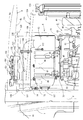
加えて、図3〜図6に示す如く、内側天板6bにセンサ設置開口部131を形成すると共に、排気差圧センサ111またはハーネスコネクタを支持するセンサブラケット132を備え、ボンネット支持枠体126にセンサブラケット132の固定脚部を締結固定させ、外側天板6aと内側天板6bの間の遮熱空間130のうち、センサ設置開口部131内方の遮熱空間130にセンサブラケット132を配置させる。電気配線コネクタを一体的に設けた差圧センサ111がセンサブラケット132に取付けられる。
In addition, as shown in FIGS. 3 to 6, a
なお、差圧センサ111には、上流側センサ配管133と下流側センサ配管134の一端側がそれぞれ接続される。第1ケース62内のスートフィルタ84を挟むように、上流側と下流側の各センサ配管ボス体151,152が第1ケース62に配置される。各センサ配管ボス体151,152に、上流側センサ配管133と下流側センサ配管134の他端側がそれぞれ接続される。
The
さらに、上流側ガス温度センサ115の電気配線用のハーネスコネクタ153と、下流側ガス温度センサ116の電気配線用のハーネスコネクタ154と、SCRガス温度センサ117の電気配線用のハーネスコネクタ155を、各ハーネス接続方向を同一方向に向けた姿勢で、センサブラケット132に固着させ、外側天板6aと内側天板6b間の遮熱空間130にセンサブラケット132を介して差圧センサ111またはハーネスコネクタ153,154,155を配置する。
Furthermore, an electrical
また、図6に示す如く、内側天板6bの下面側に近接させて、第1ケース62と第2ケース63と尿素混合管73を配置させると共に、センサ設置開口部131を開閉する蓋板体156を備え、内側天板6bの下面側に蓋板体156を着脱可能に取付け、ディーゼルエンジン5側の熱風がセンサ設置開口部131から外側天板6aと内側天板6b間の遮熱空間130内部に入るのを防止している。
Further, as shown in FIG. 6, the
図1、図3〜図9に示す如く、オペレータが搭乗する運転部としての運転キャビン7と、ディーゼルエンジン5の排気ガス中の粒子状物質を除去する第1ケース62と、ディーゼルエンジン5の排気ガス中の窒素酸化物質を除去する第2ケース63を備える作業車両において、ディーゼルエンジン5の上面側を覆うボンネット6を備える構造であって、ディーゼルエンジン5の上面側に配置する第1ケース62または第2ケース63の一方または両方に対向するボンネット6の天板部を、外側天板6aと内側天板6bにて二重構造に形成している。したがって、ボンネット6などが不適正に加熱されるのを容易に防止できるものでありながら、第1ケース62または第2ケース63の保温性などを簡単に向上できる。加えて、外側天板6aと内側天板6bの間に、差圧センサ111などを設置可能な遮熱空間130を簡単に形成できる。
As shown in FIGS. 1 and 3 to 9, an
図6〜図9に示す如く、第1ケース62または第2ケース63の排気ガス圧力または排気ガス温度を検出する排気差圧センサ111または排気温度センサ(上流側ガス温度センサ115、下流側ガス温度センサ116、SCRガス温度センサ117)と、排気差圧センサ111またはハーネスコネクタ153,154,155を支持するセンサブラケット132を備える構造であって、外側天板6aと内側天板6b間の遮熱空間130にセンサブラケット132を介して差圧センサ111またはハーネスコネクタ153,154,155を配置している。したがって、差圧センサ111またはハーネスコネクタ153,154,155に接続させるハーネスにディーゼルエンジン5または各ケース62,63の排熱が影響するのを容易に低減でき、差圧センサ111またはハーネスなどの耐久性を向上できる。
As shown in FIGS. 6 to 9, the exhaust
図6〜図9に示す如く、運転キャビン7側の走行機体2に立設させる後側フレーム122に前後連結フレーム124の後端側を連結させ、ラジエータ41側の走行機体2に立設させる前側フレーム123に前後連結フレーム124の前端側を連結させると共に、後側フレーム122に開閉支点軸125を介してボンネット6を支持させる構造であって、後側フレーム122に開閉支点軸125を介してボンネット支持枠体126を設け、ボンネット支持枠体126に外側天板6aと内側天板6bを架設している。したがって、ボンネット支持枠体126と後側フレーム122を介して外側天板6aと内側天板6bを高剛性に設置できる一方、耐熱性に乏しいが加工しやすい樹脂成型材料にて外側天板6aを形成でき、外観形状を向上できると共に、シンプルな板金形状の耐熱性材料にて内側天板6bを形成でき、ボンネット6の耐熱性を向上できる。
As shown in FIGS. 6 to 9, the rear end side of the front /
図3〜図5に示す如く、第1ケース62に第2ケース63を接続する尿素混合管73と、尿素混合管73に尿素水を供給する尿素水タンク91を備える構造であって、内側天板6bの下面側に近接させて、第1ケース62と第2ケース62と尿素混合管73を配置させると共に、ディーゼルエンジン5が搭載される走行機体2のうち、運転キャビン7下側の走行機体2に尿素水タンク91を配置している。したがって、第1ケース62と、第2ケース63と、尿素混合管73を、ディーゼルエンジン5の上面側にコンパクトに支持できる。
As shown in FIGS. 3 to 5, the structure includes a
2 走行機体
5 ディーゼルエンジン
6 ボンネット
6a 外側天板
6b 内側天板
7 運転キャビン(運転部)
41 ラジエータ
62 第1ケース
63 第2ケース
73 尿素混合管
91 尿素水タンク
111 差圧センサ
115 上流側ガス温度センサ
116 下流側ガス温度センサ
117 SCRガス温度センサ
122 後側フレーム
123 前側フレーム
124 前後連結フレーム
125 開閉支点軸
126 ボンネット支持枠体
130 遮熱空間
132 センサブラケット
153 ハーネスコネクタ
154 ハーネスコネクタ
155 ハーネスコネクタ
2 traveling
41
Claims (4)
前記エンジンの上面側を覆うボンネットを備える構造であって、前記エンジンの上面側に配置する前記第1ケースまたは前記第2ケースの一方または両方に対向する前記ボンネットの天板部を、外側天板と内側天板にて二重構造に形成したことを特徴とする作業車両。 In a work vehicle comprising an operating unit on which an operator is boarded, a first case for removing particulate matter in engine exhaust gas, and a second case for removing nitrogen oxide substance in engine exhaust gas,
A bonnet that covers the upper surface side of the engine, wherein the top plate portion of the bonnet facing one or both of the first case and the second case disposed on the upper surface side of the engine is an outer top plate. A work vehicle characterized in that it is formed in a double structure with an inner top plate.
Priority Applications (6)
| Application Number | Priority Date | Filing Date | Title |
|---|---|---|---|
| JP2013256333A JP6193109B2 (en) | 2013-12-11 | 2013-12-11 | Work vehicle |
| EP14868837.7A EP3081460A4 (en) | 2013-12-11 | 2014-12-10 | Working vehicle |
| CN201480067066.0A CN105813927A (en) | 2013-12-11 | 2014-12-10 | Working vehicle |
| PCT/JP2014/082731 WO2015087929A1 (en) | 2013-12-11 | 2014-12-10 | Working vehicle |
| US15/102,742 US9783042B2 (en) | 2013-12-11 | 2014-12-10 | Working vehicle |
| KR1020167011433A KR20160096586A (en) | 2013-12-11 | 2014-12-10 | Working vehicle |
Applications Claiming Priority (1)
| Application Number | Priority Date | Filing Date | Title |
|---|---|---|---|
| JP2013256333A JP6193109B2 (en) | 2013-12-11 | 2013-12-11 | Work vehicle |
Publications (2)
| Publication Number | Publication Date |
|---|---|
| JP2015113003A true JP2015113003A (en) | 2015-06-22 |
| JP6193109B2 JP6193109B2 (en) | 2017-09-06 |
Family
ID=53371229
Family Applications (1)
| Application Number | Title | Priority Date | Filing Date |
|---|---|---|---|
| JP2013256333A Expired - Fee Related JP6193109B2 (en) | 2013-12-11 | 2013-12-11 | Work vehicle |
Country Status (6)
| Country | Link |
|---|---|
| US (1) | US9783042B2 (en) |
| EP (1) | EP3081460A4 (en) |
| JP (1) | JP6193109B2 (en) |
| KR (1) | KR20160096586A (en) |
| CN (1) | CN105813927A (en) |
| WO (1) | WO2015087929A1 (en) |
Cited By (2)
| Publication number | Priority date | Publication date | Assignee | Title |
|---|---|---|---|---|
| JP2016112942A (en) * | 2014-12-11 | 2016-06-23 | 井関農機株式会社 | Work vehicle |
| JP2023051489A (en) * | 2021-09-30 | 2023-04-11 | 株式会社クボタ | tractor |
Families Citing this family (11)
| Publication number | Priority date | Publication date | Assignee | Title |
|---|---|---|---|---|
| JP6275552B2 (en) * | 2014-05-29 | 2018-02-07 | ヤンマー株式会社 | Work vehicle |
| CN107002532B (en) * | 2014-11-21 | 2019-07-09 | 株式会社Kcm | Industrial vehicle |
| US10308108B2 (en) | 2015-03-30 | 2019-06-04 | Kubota Corporation | Working machine |
| EP3330503B1 (en) * | 2015-07-31 | 2020-03-04 | Yanmar Co., Ltd. | Work vehicle |
| EP3443212B1 (en) | 2016-04-12 | 2023-01-25 | Cummins Power Generation Limited | Modular genset enclosure components |
| JP6619375B2 (en) * | 2017-03-24 | 2019-12-11 | ヤンマー株式会社 | Engine equipment |
| JP6815255B2 (en) * | 2017-03-30 | 2021-01-20 | ヤンマーパワーテクノロジー株式会社 | Tractor |
| JP6451805B1 (en) * | 2017-08-22 | 2019-01-16 | マツダ株式会社 | Engine heat insulation structure |
| JP6904323B2 (en) * | 2018-11-28 | 2021-07-14 | 井関農機株式会社 | Work vehicle |
| JP7575366B2 (en) * | 2021-09-30 | 2024-10-29 | 株式会社クボタ | Tractor |
| IT202300010995A1 (en) * | 2023-05-30 | 2024-11-30 | Fca Italy Spa | INTERNAL COMBUSTION ENGINE WITH OPTIMIZED INSTALLATION OF A SENSOR ASSOCIATED WITH A PARTICULATE TRAP, IN PARTICULAR A DIFFERENTIAL PRESSURE SENSOR |
Citations (8)
| Publication number | Priority date | Publication date | Assignee | Title |
|---|---|---|---|---|
| JP2001171563A (en) * | 1999-11-23 | 2001-06-26 | Deere & Co | Assembly for tractor engine enclosure |
| JP2003020936A (en) * | 2001-07-03 | 2003-01-24 | Komatsu Ltd | Arrangement structure of liquid reducing agent tank for NOx reduction catalyst |
| JP2004256006A (en) * | 2003-02-26 | 2004-09-16 | Yanmar Agricult Equip Co Ltd | Tractor |
| JP2006062425A (en) * | 2004-08-24 | 2006-03-09 | Yanmar Co Ltd | Hood and manufacturing method for hood |
| JP2008240678A (en) * | 2007-03-28 | 2008-10-09 | Komatsu Ltd | Construction vehicle |
| US20100186381A1 (en) * | 2009-01-26 | 2010-07-29 | Caterpillar Inc | Exhaust system thermal enclosure |
| JP2012062691A (en) * | 2010-09-16 | 2012-03-29 | Hitachi Constr Mach Co Ltd | Construction machinery |
| JP2013151185A (en) * | 2012-01-24 | 2013-08-08 | Iseki & Co Ltd | Working vehicle |
Family Cites Families (18)
| Publication number | Priority date | Publication date | Assignee | Title |
|---|---|---|---|---|
| US5564514A (en) * | 1994-09-09 | 1996-10-15 | New Holland North America, Inc. | Adjustable tractor hood lift mechanism |
| JPH1178987A (en) * | 1997-09-05 | 1999-03-23 | Kanzaki Kokyukoki Mfg Co Ltd | Prime mover part structure of tractor |
| JP2002021565A (en) * | 2000-07-11 | 2002-01-23 | Komatsu Ltd | Construction vehicle engine enclosure |
| JP2008240677A (en) | 2007-03-28 | 2008-10-09 | Komatsu Ltd | Construction vehicle |
| JP5239253B2 (en) * | 2007-08-14 | 2013-07-17 | 日産自動車株式会社 | Hood flip-up device |
| JP4928398B2 (en) | 2007-09-20 | 2012-05-09 | 日野自動車株式会社 | Exhaust purification device |
| GB2466483A (en) | 2008-12-19 | 2010-06-30 | Agco Gmbh & Co | A vertical exhaust system for a vehicle |
| JP5184387B2 (en) * | 2009-01-09 | 2013-04-17 | ヤンマー株式会社 | Bonnet structure |
| US20100301638A1 (en) * | 2009-05-29 | 2010-12-02 | Hinshaw Eric J | Integrated Air Intake System |
| JP2011230638A (en) * | 2010-04-27 | 2011-11-17 | Iseki & Co Ltd | Tractor |
| GB201104158D0 (en) * | 2011-03-11 | 2011-04-27 | Agco Int Gmbh | Engine hood arrangement |
| JP6137739B2 (en) * | 2011-07-08 | 2017-05-31 | 三菱マヒンドラ農機株式会社 | Work vehicle |
| US8626407B2 (en) * | 2011-07-26 | 2014-01-07 | Kubota Corporation | Work vehicle |
| JP5865040B2 (en) * | 2011-11-30 | 2016-02-17 | 株式会社クボタ | Work vehicle |
| JP2013177119A (en) | 2012-02-03 | 2013-09-09 | Hitachi Constr Mach Co Ltd | Work vehicle |
| JP2013173428A (en) | 2012-02-24 | 2013-09-05 | Iseki & Co Ltd | Work vehicle |
| JP5474155B1 (en) * | 2012-10-16 | 2014-04-16 | 株式会社小松製作所 | Exhaust treatment unit and method of attaching and removing exhaust treatment unit |
| US8720638B1 (en) * | 2013-03-29 | 2014-05-13 | Komatsu Ltd. | Bulldozer |
-
2013
- 2013-12-11 JP JP2013256333A patent/JP6193109B2/en not_active Expired - Fee Related
-
2014
- 2014-12-10 KR KR1020167011433A patent/KR20160096586A/en not_active Abandoned
- 2014-12-10 EP EP14868837.7A patent/EP3081460A4/en not_active Withdrawn
- 2014-12-10 CN CN201480067066.0A patent/CN105813927A/en active Pending
- 2014-12-10 WO PCT/JP2014/082731 patent/WO2015087929A1/en not_active Ceased
- 2014-12-10 US US15/102,742 patent/US9783042B2/en not_active Expired - Fee Related
Patent Citations (8)
| Publication number | Priority date | Publication date | Assignee | Title |
|---|---|---|---|---|
| JP2001171563A (en) * | 1999-11-23 | 2001-06-26 | Deere & Co | Assembly for tractor engine enclosure |
| JP2003020936A (en) * | 2001-07-03 | 2003-01-24 | Komatsu Ltd | Arrangement structure of liquid reducing agent tank for NOx reduction catalyst |
| JP2004256006A (en) * | 2003-02-26 | 2004-09-16 | Yanmar Agricult Equip Co Ltd | Tractor |
| JP2006062425A (en) * | 2004-08-24 | 2006-03-09 | Yanmar Co Ltd | Hood and manufacturing method for hood |
| JP2008240678A (en) * | 2007-03-28 | 2008-10-09 | Komatsu Ltd | Construction vehicle |
| US20100186381A1 (en) * | 2009-01-26 | 2010-07-29 | Caterpillar Inc | Exhaust system thermal enclosure |
| JP2012062691A (en) * | 2010-09-16 | 2012-03-29 | Hitachi Constr Mach Co Ltd | Construction machinery |
| JP2013151185A (en) * | 2012-01-24 | 2013-08-08 | Iseki & Co Ltd | Working vehicle |
Cited By (3)
| Publication number | Priority date | Publication date | Assignee | Title |
|---|---|---|---|---|
| JP2016112942A (en) * | 2014-12-11 | 2016-06-23 | 井関農機株式会社 | Work vehicle |
| JP2023051489A (en) * | 2021-09-30 | 2023-04-11 | 株式会社クボタ | tractor |
| JP7612548B2 (en) | 2021-09-30 | 2025-01-14 | 株式会社クボタ | Tractor |
Also Published As
| Publication number | Publication date |
|---|---|
| JP6193109B2 (en) | 2017-09-06 |
| CN105813927A (en) | 2016-07-27 |
| EP3081460A1 (en) | 2016-10-19 |
| US9783042B2 (en) | 2017-10-10 |
| US20160311314A1 (en) | 2016-10-27 |
| EP3081460A4 (en) | 2017-08-02 |
| WO2015087929A1 (en) | 2015-06-18 |
| KR20160096586A (en) | 2016-08-16 |
Similar Documents
| Publication | Publication Date | Title |
|---|---|---|
| JP6193109B2 (en) | Work vehicle | |
| US9855837B2 (en) | Work vehicle | |
| JP5956373B2 (en) | Engine device for work vehicle | |
| US9505301B2 (en) | Engine device | |
| JP6200682B2 (en) | Tractor | |
| JP6188219B2 (en) | Tractor | |
| JP5918154B2 (en) | Engine device for work vehicle | |
| JP2017025743A (en) | Engine device | |
| JP6157966B2 (en) | Tractor | |
| JP6177005B2 (en) | Work vehicle | |
| JP6162519B2 (en) | Tractor | |
| JP2014190327A (en) | Engine device | |
| JP2015117597A (en) | Work vehicle | |
| JP6216413B2 (en) | Tractor | |
| JP2014190328A (en) | Engine device | |
| JP6255327B2 (en) | Engine equipment | |
| JP6177118B2 (en) | Tractor | |
| JP6151629B2 (en) | Work vehicle | |
| JP6120796B2 (en) | Work vehicle | |
| WO2015012169A1 (en) | Working vehicle | |
| JP2015021479A (en) | Work vehicle | |
| JP2017008947A (en) | Work vehicle | |
| JP2015020714A (en) | Work vehicle | |
| WO2015087928A1 (en) | Working vehicle |
Legal Events
| Date | Code | Title | Description |
|---|---|---|---|
| A621 | Written request for application examination |
Free format text: JAPANESE INTERMEDIATE CODE: A621 Effective date: 20160322 |
|
| A131 | Notification of reasons for refusal |
Free format text: JAPANESE INTERMEDIATE CODE: A131 Effective date: 20160928 |
|
| A521 | Request for written amendment filed |
Free format text: JAPANESE INTERMEDIATE CODE: A523 Effective date: 20161128 |
|
| A131 | Notification of reasons for refusal |
Free format text: JAPANESE INTERMEDIATE CODE: A131 Effective date: 20170405 |
|
| A521 | Request for written amendment filed |
Free format text: JAPANESE INTERMEDIATE CODE: A523 Effective date: 20170530 |
|
| TRDD | Decision of grant or rejection written | ||
| A01 | Written decision to grant a patent or to grant a registration (utility model) |
Free format text: JAPANESE INTERMEDIATE CODE: A01 Effective date: 20170802 |
|
| A61 | First payment of annual fees (during grant procedure) |
Free format text: JAPANESE INTERMEDIATE CODE: A61 Effective date: 20170809 |
|
| R150 | Certificate of patent or registration of utility model |
Ref document number: 6193109 Country of ref document: JP Free format text: JAPANESE INTERMEDIATE CODE: R150 |
|
| R250 | Receipt of annual fees |
Free format text: JAPANESE INTERMEDIATE CODE: R250 |
|
| S533 | Written request for registration of change of name |
Free format text: JAPANESE INTERMEDIATE CODE: R313533 |
|
| R350 | Written notification of registration of transfer |
Free format text: JAPANESE INTERMEDIATE CODE: R350 |
|
| LAPS | Cancellation because of no payment of annual fees |