JP2015114163A - Magnetic characteristic measurement instrument - Google Patents
Magnetic characteristic measurement instrument Download PDFInfo
- Publication number
- JP2015114163A JP2015114163A JP2013255284A JP2013255284A JP2015114163A JP 2015114163 A JP2015114163 A JP 2015114163A JP 2013255284 A JP2013255284 A JP 2013255284A JP 2013255284 A JP2013255284 A JP 2013255284A JP 2015114163 A JP2015114163 A JP 2015114163A
- Authority
- JP
- Japan
- Prior art keywords
- test piece
- case
- upper case
- lower case
- annular
- Prior art date
- Legal status (The legal status is an assumption and is not a legal conclusion. Google has not performed a legal analysis and makes no representation as to the accuracy of the status listed.)
- Pending
Links
Images
Landscapes
- Measuring Magnetic Variables (AREA)
Abstract
Description
本発明は、磁性材料で形成された環状の試験片の磁気特性を測定する磁気特性測定装置に関する。 The present invention relates to a magnetic property measuring apparatus for measuring magnetic properties of an annular test piece made of a magnetic material.
磁性材料の磁気特性を測定する方法の一例として、環状の試験片に励磁コイル(一次巻線)及び検出コイル(二次巻線)を巻回し、印加磁界における磁束密度の変化を測定する測定方法が公知である。このような測定方法においては、励磁コイル及び検出コイルをリング試験片に手作業で巻く必要があり、しかも均一かつ密に巻く必要があるため、その作業が大きな負担となる。また測定後、励磁コイル及び検出コイルを外してしまうと、再度測定が必要になったときに、改めて励磁コイル及び検出コイルをリング試験片に巻かなければならない。 As an example of a method for measuring the magnetic properties of a magnetic material, a measuring method in which an excitation coil (primary winding) and a detection coil (secondary winding) are wound around an annular test piece and a change in magnetic flux density in an applied magnetic field is measured. Is known. In such a measuring method, it is necessary to manually wind the excitation coil and the detection coil around the ring test piece, and it is necessary to wind the coil uniformly and densely, which is a heavy burden. If the excitation coil and the detection coil are removed after the measurement, the excitation coil and the detection coil must be wound around the ring test piece again when measurement is required again.
このような課題を解決することを目的とした従来技術の一例として、環状の測定対象物が周方向に分割されてなる複数の試料片の各々をスライド収納する複数の試料収納部と、試料収納部に収納される複数の試料片を磁気的に接続する接続部と、試料収納部の外周に巻回された励磁コイル及び検出コイルとを備える環状試料磁気特性測定装置が公知である(例えば特許文献1を参照)。このような従来技術によれば、磁気特性の測定の度に励磁コイル及び検出コイルを環状の試験片に手作業で巻く必要がないので、試験片の磁気特性を測定する際の作業負担を低減することができる。 As an example of the prior art aiming to solve such problems, a plurality of sample storage units for slidingly storing each of a plurality of sample pieces in which an annular measurement object is divided in the circumferential direction, and sample storage An annular sample magnetic property measuring apparatus is known that includes a connection part for magnetically connecting a plurality of sample pieces housed in a part, and an excitation coil and a detection coil wound around the outer periphery of the sample storage part (for example, a patent) Reference 1). According to such a conventional technique, it is not necessary to manually wind the excitation coil and the detection coil around the annular test piece every time the magnetic characteristic is measured, so that the work load when measuring the magnetic characteristic of the test piece is reduced. can do.
しかしながら上記の従来技術においては、環状の試験片をそのまま用いることはできず、環状の試験片を複数に分断する必要があり、さらにその複数の試料片を接続するU字状カットコア等の接続部材も必要となる。つまり上記の従来技術は、磁性材料の磁気特性を測定する際に準備する試験片の製作に多大な労力を要するという課題がある。 However, in the above-described prior art, the annular test piece cannot be used as it is, and it is necessary to divide the annular test piece into a plurality of pieces, and furthermore, a connection such as a U-shaped cut core for connecting the plurality of sample pieces. A member is also required. In other words, the above-described conventional technique has a problem that it takes a lot of labor to manufacture a test piece prepared when measuring the magnetic properties of a magnetic material.
このような状況に鑑み本発明はなされたものであり、その目的は、環状の試験片の磁気特性を測定する際に、その環状の試験片をそのまま用いることができ、しかも磁気特性の測定の度に励磁コイル及び検出コイルを環状の試験片に手作業で巻く必要がない磁気特性測定装置を提供することにある。 In view of such circumstances, the present invention has been made. The purpose of the present invention is to measure the magnetic properties of an annular test piece, and the annular test piece can be used as it is. It is an object of the present invention to provide a magnetic property measuring apparatus that does not require manual winding of an excitation coil and a detection coil around an annular test piece.
<本発明の第1の態様>
本発明の第1の態様は、絶縁性を有する材料で形成され、磁性材料で形成された環状の試験片が収容される環状の凹部が設けられた第1部材と、絶縁性を有する材料で形成され、前記環状の凹部の開口を塞ぐように前記第1部材と組み合わされる第2部材と、を備え、前記第1部材は、複数の第1端子と、前記複数の第1端子の各々に接続された複数の第1導電路と、を含み、前記第2部材は、前記第1部材と組み合わせた状態で前記複数の第1端子の各々に接続される複数の第2端子と、前記複数の第2端子の各々に接続された複数の第2導電路と、を含み、前記第1部材と前記第2部材とを組み合わせた状態で、前記複数の第1導電路及び前記複数の第2導電路によって、前記環状の凹部に収容された環状の試験片の外周に巻回される励磁コイル及び検出コイルが構成される、磁気特性測定装置である。
<First Aspect of the Present Invention>
A first aspect of the present invention is a first member that is formed of an insulating material and is provided with an annular recess that accommodates an annular test piece formed of a magnetic material, and an insulating material. A second member that is formed and combined with the first member so as to close the opening of the annular recess, and the first member is connected to each of the plurality of first terminals and each of the plurality of first terminals. A plurality of first conductive paths connected to each other, and the second member is connected to each of the plurality of first terminals in combination with the first member; A plurality of second conductive paths connected to each of the second terminals, and in a state where the first member and the second member are combined, the plurality of first conductive paths and the plurality of second conductive paths Excitation wound around the outer periphery of the annular test piece accommodated in the annular recess by the conductive path. Coil and the detection coil constitute a magnetic characteristic measuring apparatus.
本発明の第1の態様においては、第1部材と第2部材とを組み合わせることによって、第1部材の複数の第1端子と第2部材の複数の第2端子とが各々接続される。それによって第1部材の複数の第1導電路と第2部材の複数の第2導電路とが各々接続されることになる。そしてその複数の第1導電路と複数の第2導電路によって、環状の試験片の外周に巻回される励磁コイル及び検出コイルが構成される。つまり本発明に係る磁気特性測定装置は、環状の凹部に環状の試験片を収容した状態で第1部材と第2部材とを組み合わせるだけで、その環状の試験片の外周に巻回される励磁コイル及び検出コイルを構成することができる。 In the first aspect of the present invention, the plurality of first terminals of the first member and the plurality of second terminals of the second member are respectively connected by combining the first member and the second member. Thereby, the plurality of first conductive paths of the first member and the plurality of second conductive paths of the second member are respectively connected. The plurality of first conductive paths and the plurality of second conductive paths constitute an excitation coil and a detection coil wound around the outer periphery of the annular test piece. That is, the magnetic property measuring apparatus according to the present invention is an excitation wound around the outer periphery of the annular test piece simply by combining the first member and the second member in a state where the annular test piece is accommodated in the annular recess. A coil and a detection coil can be configured.
これにより本発明の第1の態様によれば、環状の試験片の磁気特性を測定する際に、その環状の試験片をそのまま用いることができ、しかも磁気特性の測定の度に励磁コイル及び検出コイルを環状の試験片に手作業で巻く必要がない磁気特性測定装置を提供できるという作用効果が得られる。 Thus, according to the first aspect of the present invention, when measuring the magnetic properties of the annular test piece, the annular test piece can be used as it is, and the excitation coil and the detection are detected each time the magnetic property is measured. The effect of providing a magnetic property measuring apparatus that does not require the coil to be manually wound around an annular test piece can be obtained.
<本発明の第2の態様>
本発明の第2の態様は、前述した本発明の第1の態様において、前記第1端子及び前記第2端子は、いずれか一方が雄端子であり、他方は前記雄端子が嵌合する雌端子である、磁気特性測定装置である。
本発明の第2の態様によれば、第1部材と第2部材とを組み合わせた状態において、第1部材の複数の第1導電路と第2部材の複数の第2導電路とを確実に接続することができるとともに、その第1部材と第2部材とを組み合わせた状態を強固に保持することができる。
<Second Aspect of the Present Invention>
According to a second aspect of the present invention, in the first aspect of the present invention described above, one of the first terminal and the second terminal is a male terminal, and the other is a female to which the male terminal is fitted. This is a magnetic characteristic measuring device that is a terminal.
According to the second aspect of the present invention, in a state where the first member and the second member are combined, the plurality of first conductive paths of the first member and the plurality of second conductive paths of the second member are reliably provided. While being able to connect, the state which combined the 1st member and the 2nd member can be held firmly.
<本発明の第3の態様>
本発明の第3の態様は、前述した本発明の第1の態様又は第2の態様において、前記複数の第1導電路は、前記第1部材の表面に形成された導体パターンであり、前記複数の第2導電路は、前記第2部材の表面に形成された導体パターンである、磁気特性測定装置である。
本発明の第3の態様によれば、第1導電路及び第2導電路が導体パターンで形成されているので、環状の試験片の外周に均一かつ密に巻回される励磁コイル及び検出コイルを容易に構成することができる。また本発明の第3の態様によれば、第1導電路及び第2導電路が導体パターンで形成されているので、第1導電路又は第2導電路に断線等が生ずる虞を低減することができるとともに、本発明に係る磁気特性測定装置を低コストで量産することができる。
<Third Aspect of the Present Invention>
According to a third aspect of the present invention, in the first aspect or the second aspect of the present invention described above, the plurality of first conductive paths are conductor patterns formed on a surface of the first member, The plurality of second conductive paths is a magnetic property measuring apparatus that is a conductor pattern formed on the surface of the second member.
According to the third aspect of the present invention, since the first conductive path and the second conductive path are formed by the conductor pattern, the excitation coil and the detection coil wound uniformly and densely around the outer periphery of the annular test piece Can be configured easily. Moreover, according to the 3rd aspect of this invention, since the 1st conductive path and the 2nd conductive path are formed with the conductor pattern, reducing a possibility that a disconnection etc. may arise in a 1st conductive path or a 2nd conductive path. In addition, the magnetic property measuring apparatus according to the present invention can be mass-produced at a low cost.
本発明によれば、環状の試験片の磁気特性を測定する際に、その環状の試験片をそのまま用いることができ、しかも磁気特性の測定の度に励磁コイル及び検出コイルを環状の試験片に手作業で巻く必要がない磁気特性測定装置を提供することができる。 According to the present invention, when measuring the magnetic properties of an annular test piece, the annular test piece can be used as it is, and the excitation coil and the detection coil are converted into an annular test piece each time the magnetic properties are measured. It is possible to provide a magnetic property measuring apparatus that does not require manual winding.
以下、本発明の実施の形態について図面を参照しながら説明する。
尚、本発明は、以下説明する実施例に特に限定されるものではなく、特許請求の範囲に記載された発明の範囲内で種々の変形が可能であることは言うまでもない。
Hereinafter, embodiments of the present invention will be described with reference to the drawings.
In addition, this invention is not specifically limited to the Example demonstrated below, It cannot be overemphasized that a various deformation | transformation is possible within the range of the invention described in the claim.
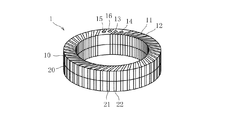
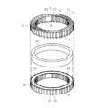
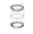
図1は、試験片ケース1の斜視図である。図2は、試験片ケース1の上ケース10と下ケース20とを分離させた状態を図示した斜視図であり、上ケース10側から観た斜視図である。図3は、試験片ケース1の上ケース10と下ケース20とを分離させた状態を図示した斜視図であり、下ケース20側から観た斜視図である。
FIG. 1 is a perspective view of the
本発明に係る「磁気特性測定装置」としての試験片ケース1は、上ケース10と下ケース20とを備える。
A
「第1部材」としての上ケース10は、例えばプラスチック等の絶縁性を有する材料で形成されており、複数の第1励磁コイルパターン11、複数の第1検出コイルパターン12、第1入力端子13、第1出力端子14、第2入力端子15、第2出力端子16、第1凹部17、複数の内側雄端子18、複数の外側雄端子19を含む。
The
「複数の第1導電路」としての複数の第1励磁コイルパターン11及び複数の第1検出コイルパターン12は、上ケース10の表面に形成された複数の導体パターンである。より具体的には、複数の第1励磁コイルパターン11及び複数の第1検出コイルパターン12は、上ケース10の内側面から上面、外側面に亘って各々形成された複数の導体パターンである。第1励磁コイルパターン11と第1検出コイルパターン12は、周方向に一本ずつ交互に形成されている。第1入力端子13、第1出力端子14、第2入力端子15及び第2出力端子16は、上ケース10の上面に形成されており、例えば電線等を半田付けで接続可能なランドである。「複数の第1端子」としての複数の内側雄端子18は、第1凹部17の内側の開口端に設けられており、第1励磁コイルパターン11及び第1検出コイルパターン12の一端側が各々一対一で接続されている。また「複数の第1端子」としての複数の外側雄端子19は、第1凹部17の外側の開口端に設けられており、第1励磁コイルパターン11及び第1検出コイルパターン12の他端側が各々一対一で接続されている。「環状の凹部」としての第1凹部17は、円環状の試験片30が収容される円環状の凹部である。
The plurality of first
「第2部材」としての下ケース20は、例えばプラスチック等の絶縁性を有する材料で形成されており、複数の第2励磁コイルパターン21、複数の第2検出コイルパターン22、円環状の第2凹部23、複数の内側雌端子24、複数の外側雌端子25を含む。
The
下ケース20は、上ケース10と組み合わされた状態で試験片ケース1を構成する部材である。ここで上ケース10と下ケース20とを組み合わせた状態とは、上ケース10の第1凹部17の開口を塞ぐように上ケース10と下ケース20とが組み合わされ、上ケース10と下ケース20とが一体になって試験片ケース1を構成する状態をいう。より具体的には、上ケース10の第1凹部17の内側の開口端と下ケース20の第2凹部23の内側の開口端とが当接し、上ケース10の第1凹部17の外側の開口端と下ケース20の第2凹部23の外側の開口端とが当接した状態をいう。そして上ケース10と下ケース20とを組み合わせた状態において試験片ケース1は、上ケース10の円環状の第1凹部17と下ケース20の円環状の第2凹部23とで、円環状の試験片30が収容される円環状の空間が内部に構成される。
The
「複数の第2導電路」としての複数の第2励磁コイルパターン21及び複数の第2検出コイルパターン22は、下ケース20の表面に形成された複数の導体パターンである。より具体的には、複数の第2励磁コイルパターン21及び複数の第2検出コイルパターン22は、下ケース20の内側面から上面、外側面に亘って各々形成された複数の導体パターンである。第2励磁コイルパターン21と第2検出コイルパターン22は、周方向に一本ずつ交互に形成されている。
The plurality of second
「複数の第2端子」としての複数の内側雌端子24は、第2凹部23の内側の開口端に設けられており、第2励磁コイルパターン21及び第2検出コイルパターン22の一端側が各々一対一で接続されている。複数の内側雌端子24は、上ケース10と下ケース20とを組み合わせた状態で上ケース10の複数の内側雄端子18が各々嵌合する。それによって複数の内側雌端子24は、上ケース10の複数の内側雄端子18の各々に接続される。また「複数の第2端子」としての複数の外側雌端子25は、第2凹部23の外側の開口端に設けられており、第2励磁コイルパターン21及び第2検出コイルパターン22の他端側が各々一対一で接続されている。複数の外側雌端子25は、上ケース10と下ケース20とを組み合わせた状態で上ケース10の複数の外側雄端子19が各々嵌合する。それによって複数の外側雌端子25は、上ケース10の複数の外側雄端子19の各々に接続される。
A plurality of inner
試験片ケース1は、上ケース10と下ケース20とを組み合わせた状態で、上ケース10の第1励磁コイルパターン11と下ケース20の第2励磁コイルパターン21によって、内部の円環状の空間に収容された円環状の試験片30の外周に巻回される励磁コイルL1が構成される。また試験片ケース1は、上ケース10と下ケース20とを組み合わせた状態で、上ケース10の第1検出コイルパターン12と下ケース20の第2検出コイルパターン22によって、内部の円環状の空間に収容された円環状の試験片30の外周に巻回される検出コイルL2が構成される。以下、図4を参照しながらより具体的に説明する。
In the state where the
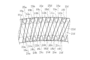
図4は、試験片ケース1の一部を拡大図示した平面図である。
FIG. 4 is an enlarged plan view showing a part of the
上ケース10の第1励磁コイルパターン11aの一端側は、上ケース10の第1入力端子13に接続されている。他方、上ケース10の第1励磁コイルパターン11aの他端側は、上ケース10の外側雄端子19aに接続されている。上ケース10の外側雄端子19aは、下ケース20の外側雌端子25aに嵌合している。下ケース20の外側雌端子25aには、下ケース20の第2励磁コイルパターン21aの一端側が接続されている。つまり上ケース10の第1励磁コイルパターン11aの他端側は、下ケース20の第2励磁コイルパターン21aの一端側に接続されている。
One end side of the first
下ケース20の第2励磁コイルパターン21aの他端側は、下ケース20の内側雌端子24bに接続されている。下ケース20の内側雌端子24bは、上ケース10の内側雄端子18bに嵌合している。上ケース10の内側雄端子18bには、上ケース10の第1励磁コイルパターン11bの一端側が接続されている。つまり下ケース20の第2励磁コイルパターン21aの他端側は、上ケース10の第1励磁コイルパターン11bの一端側に接続されている。
The other end side of the second
上ケース10の第1励磁コイルパターン11bの他端側は、上ケース10の外側雄端子19cに接続されている。上ケース10の外側雄端子19cは、下ケース20の外側雌端子25cに嵌合している。下ケース20の外側雌端子25cには、下ケース20の第2励磁コイルパターン21bの一端側が接続されている。つまり上ケース10の第1励磁コイルパターン11bの他端側は、下ケース20の第2励磁コイルパターン21bの一端側に接続されている。
The other end side of the first
下ケース20の第2励磁コイルパターン21bの他端側は、下ケース20の内側雌端子24dに接続されている。下ケース20の内側雌端子24dは、上ケース10の内側雄端子18dに嵌合している。上ケース10の内側雄端子18dには、上ケース10の第1励磁コイルパターン11cの一端側が接続されている。つまり下ケース20の第2励磁コイルパターン21bの他端側は、上ケース10の第1励磁コイルパターン11cの一端側に接続されている。
The other end side of the second excitation coil pattern 21 b of the
上ケース10の第1励磁コイルパターン11cの他端側は、上ケース10の外側雄端子19eに接続されている。上ケース10の外側雄端子19eは、下ケース20の外側雌端子25eに嵌合している。下ケース20の外側雌端子25eには、下ケース20の第2励磁コイルパターン21cの一端側が接続されている。つまり上ケース10の第1励磁コイルパターン11cの他端側は、下ケース20の第2励磁コイルパターン21cの一端側に接続されている。
The other end side of the first
下ケース20の第2励磁コイルパターン21cの他端側は、下ケース20の内側雌端子24fに接続されている。下ケース20の内側雌端子24fは、上ケース10の内側雄端子18fに嵌合している。上ケース10の内側雄端子18fには、上ケース10の第1励磁コイルパターン11dの一端側が接続されている。つまり下ケース20の第2励磁コイルパターン21cの他端側は、上ケース10の第1励磁コイルパターン11dの一端側に接続されている。
The other end side of the second
このようにして試験片ケース1は、上ケース10と下ケース20とを組み合わせた状態では、上ケース10の複数の第1励磁コイルパターン11と下ケース20の複数の第2励磁コイルパターン21とが交互に直列に接続される。それによって試験片ケース1には、内部の円環状の空間に収容された円環状の試験片30の外周に巻回される励磁コイルL1が構成されることになる。より具体的には試験片ケース1には、一端側が上ケース10の第1入力端子13に接続され、他端側が上ケース10の第2入力端子15に接続された一本の励磁コイルL1が構成されることになる。
In this way, the
下ケース20の第2検出コイルパターン22aの一端側は、下ケース20の外側雌端子25、上ケース10の外側雄端子19、上ケース10の第1検出コイルパターン12を介して、最終的に上ケース10の第1出力端子14に接続されている(図示省略)。
下ケース20の第2検出コイルパターン22aの他端側は、下ケース20の内側雌端子24aに接続されている。下ケース20の内側雌端子24aは、上ケース10の内側雄端子18aに嵌合している。上ケース10の内側雄端子18aには、上ケース10の第1検出コイルパターン12aの一端側が接続されている。つまり下ケース20の第2検出コイルパターン22aの他端側は、上ケース10の第1検出コイルパターン12aの一端側に接続されている。
One end side of the second
The other end side of the second
上ケース10の第1検出コイルパターン12aの他端側は、上ケース10の外側雄端子19bに接続されている。上ケース10の外側雄端子19bは、下ケース20の外側雌端子25bに嵌合している。下ケース20の外側雌端子25bには、下ケース20の第2検出コイルパターン22bの一端側が接続されている。つまり上ケース10の第1検出コイルパターン12aの他端側は、下ケース20の第2検出コイルパターン22bの一端側に接続されている。
The other end side of the first
下ケース20の第2検出コイルパターン22bの他端側は、下ケース20の内側雌端子24cに接続されている。下ケース20の内側雌端子24cは、上ケース10の内側雄端子18cに嵌合している。上ケース10の内側雄端子18cには、上ケース10の第1検出コイルパターン12bの一端側が接続されている。つまり下ケース20の第2検出コイルパターン22bの他端側は、上ケース10の第1検出コイルパターン12bの一端側に接続されている。
The other end side of the second
上ケース10の第1検出コイルパターン12bの他端側は、上ケース10の外側雄端子19dに接続されている。上ケース10の外側雄端子19dは、下ケース20の外側雌端子25dに嵌合している。下ケース20の外側雌端子25dには、下ケース20の第2検出コイルパターン22cの一端側が接続されている。つまり上ケース10の第1検出コイルパターン12bの他端側は、下ケース20の第2検出コイルパターン22cの一端側に接続されている。
The other end of the first
下ケース20の第2検出コイルパターン22cの他端側は、下ケース20の内側雌端子24eに接続されている。下ケース20の内側雌端子24eは、上ケース10の内側雄端子18eに嵌合している。上ケース10の内側雄端子18eには、上ケース10の第1検出コイルパターン12cの一端側が接続されている。つまり下ケース20の第2検出コイルパターン22cの他端側は、上ケース10の第1検出コイルパターン12cの一端側に接続されている。
The other end side of the second
上ケース10の第1検出コイルパターン12cの他端側は、上ケース10の外側雄端子19fに接続されている。上ケース10の外側雄端子19fは、下ケース20の外側雌端子25fに嵌合している。下ケース20の外側雌端子25fには、下ケース20の第2検出コイルパターン22dの一端側が接続されている。つまり上ケース10の第1検出コイルパターン12cの他端側は、下ケース20の第2検出コイルパターン22dの一端側に接続されている。
The other end side of the first
このようにして試験片ケース1は、上ケース10と下ケース20とを組み合わせた状態では、上ケース10の複数の第1検出コイルパターン12と下ケース20の複数の第2検出コイルパターン22とが交互に直列に接続される。それによって試験片ケース1には、内部の円環状の空間に収容された円環状の試験片30の外周に巻回される検出コイルL2が構成されることになる。より具体的には試験片ケース1には、一端側が上ケース10の第1出力端子14に接続され、他端側が上ケース10の第2出力端子16に接続された一本の検出コイルL2が構成されることになる。
Thus, in the state where the
以上説明したように本発明に係る試験片ケース1は、上ケース10に設けられた円環状の第1凹部17と下ケース20に設けられた円環状の第2凹部23とで構成される円環状の内部空間に円環状の試験片30を収容した状態で、上ケース10と下ケース20とを組み合わせるだけで、その円環状の試験片30の外周に巻回される励磁コイルL1及び検出コイルL2を構成することができる。したがって本発明に係る試験片ケース1によれば、円環状の試験片30の磁気特性を測定する際に、その円環状の試験片30をそのまま用いることができ、しかも磁気特性の測定の度に励磁コイルL1及び検出コイルL2を円環状の試験片30に手作業で巻く必要がない。
As described above, the
また本発明に係る試験片ケース1において上ケース10の「第1端子」及び下ケース20の「第2端子」は、上記説明した実施例のように、いずれか一方が雄端子(内側雄端子18、外側雄端子19)であり、他方はその雄端子が嵌合する雌端子(内側雌端子24、外側雌端子25)であるのが好ましい。それによって上ケース10と下ケース20とを組み合わせた状態において、上ケース10の複数の第1励磁コイルパターン11と下ケース20の複数の第2励磁コイルパターン21とを各々確実に接続することができるとともに、上ケース10の複数の第1検出コイルパターン12と下ケース20の複数の第2検出コイルパターン22とを各々確実に接続することができる。さらに上ケース10と下ケース20とを組み合わせた状態を強固に保持することができる。
In the
また本発明に係る試験片ケース1において上ケース10の「複数の第1導電路」は、上記説明した実施例のように、上ケース10の表面に形成された導体パターン(第1励磁コイルパターン11、第1検出コイルパターン12)であるのが好ましい。同様に下ケース20の「複数の第2導電路」は、上記説明した実施例のように、下ケース20の表面に形成された導体パターン(第2励磁コイルパターン21、第2検出コイルパターン22)であるのが好ましい。それによって円環状の試験片30の外周に均一かつ密に巻回される励磁コイルL1及び検出コイルL2を容易に構成することができる。また例えば上ケース10の「第1導電路」又は下ケース20の「第2導電路」を電線で構成した場合と比較して、断線等が生ずる虞を低減することができるとともに、本発明に係る試験片ケース1を低コストで量産することができる。
In the
また上記実施例では、上ケース10の第1凹部17と下ケース20の第2凹部23とで試験片ケース1に円環状の内部空間が構成される態様を例に説明したが、例えば下ケース20に第2凹部23を設けずに、下ケース20を円環状の平板とし、上ケース10の第1凹部17だけで試験片ケース1に円環状の内部空間を構成することも可能であり、そのような態様でも本発明は実施することができる。また上記実施例では、円環状の試験片30を例に説明したが、例えば矩形環状の試験片30の磁気特性を測定する場合には、それに合わせて試験片ケース1の形状や上ケース10の第1凹部17の形状、下ケース20の第2凹部23の形状等を決定すればよい。
In the above embodiment, an example in which the annular inner space is formed in the
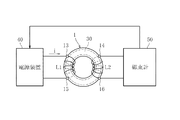
図5は、本発明に係る試験片ケース1を用いて磁性材料の磁気特性を測定する方法の一例として、円環状の試験片30の磁気特性を励磁電流法により計測する装置の構成を図示したブロック図である。
FIG. 5 illustrates the configuration of an apparatus for measuring the magnetic properties of an
前述したように試験片ケース1には、上ケース10の複数の第1励磁コイルパターン11と下ケース20の複数の第2励磁コイルパターン21によって、内部の円環状の空間に収容された円環状の試験片30の外周に巻回される励磁コイルL1が構成されている。励磁コイルL1は、一端側が第1入力端子13に接続され、他端側が第2入力端子15に接続されている。試験片ケース1の第1入力端子13及び第2入力端子15は、電源装置40に接続されている。
As described above, the
また前述したように試験片ケース1には、上ケース10の複数の第1検出コイルパターン12と下ケース20の複数の第2検出コイルパターン22とによって、内部の円環状の空間に収容された円環状の試験片30の外周に巻回される検出コイルL2が構成されている。検出コイルL2は、一端側が第1出力端子14に接続され、他端側が第2出力端子16に接続されている。試験片ケース1の第1出力端子14及び第2出力端子16は、磁束計50に接続されている。また磁束計50は、電源装置40に接続されており、励磁コイルL1の駆動信号が磁束計50から電源装置40へ出力される。
Further, as described above, the
例えば励磁コイルL1の巻数と電流iから試験片30に作用する磁界の強さを求める。また検出コイルL2の巻数と断面積、及び検出コイルL2が検出する磁束から試験片30の磁束密度を求める。それによって試験片30の磁気特性を測定することができる。
For example, the strength of the magnetic field acting on the
1 試験片ケース
10 上ケース
11 第1励磁コイルパターン
12 第1検出コイルパターン
13 第1入力端子
14 第1出力端子
15 第2入力端子
16 第2出力端子
17 第1凹部
18 第1内側雄端子
19 第1外側雄端子
20 下ケース
21 第2励磁コイルパターン
22 第2検出コイルパターン
23 第2凹部
24 第2内側雌端子
25 第2外側雌端子
30 試験片
40 電源装置
50 磁束計
L1 励磁コイル
L2 検出コイル
DESCRIPTION OF
Claims (3)
絶縁性を有する材料で形成され、前記環状の凹部の開口を塞ぐように前記第1部材と組み合わされる第2部材と、を備え、
前記第1部材は、複数の第1端子と、前記複数の第1端子の各々に接続された複数の第1導電路と、を含み、
前記第2部材は、前記第1部材と組み合わせた状態で前記複数の第1端子の各々に接続される複数の第2端子と、前記複数の第2端子の各々に接続された複数の第2導電路と、を含み、
前記第1部材と前記第2部材とを組み合わせた状態で、前記複数の第1導電路及び前記複数の第2導電路によって、前記環状の凹部に収容された環状の試験片の外周に巻回される励磁コイル及び検出コイルが構成される、磁気特性測定装置。 A first member formed of an insulating material and provided with an annular recess for receiving an annular test piece formed of a magnetic material;
A second member formed of an insulating material and combined with the first member so as to close the opening of the annular recess,
The first member includes a plurality of first terminals and a plurality of first conductive paths connected to each of the plurality of first terminals.
The second member includes a plurality of second terminals connected to each of the plurality of first terminals in combination with the first member, and a plurality of second terminals connected to each of the plurality of second terminals. A conductive path,
In a state where the first member and the second member are combined, the coil is wound around the outer periphery of the annular test piece accommodated in the annular recess by the plurality of first conductive paths and the plurality of second conductive paths. A magnetic characteristic measuring device comprising an excitation coil and a detection coil.
Priority Applications (1)
| Application Number | Priority Date | Filing Date | Title |
|---|---|---|---|
| JP2013255284A JP2015114163A (en) | 2013-12-10 | 2013-12-10 | Magnetic characteristic measurement instrument |
Applications Claiming Priority (1)
| Application Number | Priority Date | Filing Date | Title |
|---|---|---|---|
| JP2013255284A JP2015114163A (en) | 2013-12-10 | 2013-12-10 | Magnetic characteristic measurement instrument |
Publications (1)
| Publication Number | Publication Date |
|---|---|
| JP2015114163A true JP2015114163A (en) | 2015-06-22 |
Family
ID=53528092
Family Applications (1)
| Application Number | Title | Priority Date | Filing Date |
|---|---|---|---|
| JP2013255284A Pending JP2015114163A (en) | 2013-12-10 | 2013-12-10 | Magnetic characteristic measurement instrument |
Country Status (1)
| Country | Link |
|---|---|
| JP (1) | JP2015114163A (en) |
Cited By (2)
| Publication number | Priority date | Publication date | Assignee | Title |
|---|---|---|---|---|
| KR102391742B1 (en) * | 2021-11-22 | 2022-04-27 | 한전케이피에스 주식회사 | Detector Test System |
| DE102024124068B3 (en) * | 2024-08-22 | 2026-01-15 | Technische Universität Chemnitz, Körperschaft des öffentlichen Rechts | Device for determining the magnetic properties of ring samples |
Citations (4)
| Publication number | Priority date | Publication date | Assignee | Title |
|---|---|---|---|---|
| JPS58101178U (en) * | 1981-12-28 | 1983-07-09 | 横河電機株式会社 | Circular magnetic sample measurement coil |
| JPS62158371U (en) * | 1986-03-31 | 1987-10-07 | ||
| JPH0576507A (en) * | 1991-09-24 | 1993-03-30 | Mitsubishi Electric Corp | Gradient magnetic field coil and production thereof |
| JP2004198224A (en) * | 2002-12-18 | 2004-07-15 | Iwatsu Electric Co Ltd | Method and apparatus for forming coil for seamless magnetic measurement |
-
2013
- 2013-12-10 JP JP2013255284A patent/JP2015114163A/en active Pending
Patent Citations (4)
| Publication number | Priority date | Publication date | Assignee | Title |
|---|---|---|---|---|
| JPS58101178U (en) * | 1981-12-28 | 1983-07-09 | 横河電機株式会社 | Circular magnetic sample measurement coil |
| JPS62158371U (en) * | 1986-03-31 | 1987-10-07 | ||
| JPH0576507A (en) * | 1991-09-24 | 1993-03-30 | Mitsubishi Electric Corp | Gradient magnetic field coil and production thereof |
| JP2004198224A (en) * | 2002-12-18 | 2004-07-15 | Iwatsu Electric Co Ltd | Method and apparatus for forming coil for seamless magnetic measurement |
Cited By (2)
| Publication number | Priority date | Publication date | Assignee | Title |
|---|---|---|---|---|
| KR102391742B1 (en) * | 2021-11-22 | 2022-04-27 | 한전케이피에스 주식회사 | Detector Test System |
| DE102024124068B3 (en) * | 2024-08-22 | 2026-01-15 | Technische Universität Chemnitz, Körperschaft des öffentlichen Rechts | Device for determining the magnetic properties of ring samples |
Similar Documents
| Publication | Publication Date | Title |
|---|---|---|
| JP6423269B2 (en) | Common mode choke coil | |
| US9437360B2 (en) | Structure of transformer | |
| TWI637410B (en) | transformer | |
| US9817037B2 (en) | Electrical current transducer with wound magnetic core | |
| US9423428B2 (en) | Mixed current sensor and method for fitting said sensor | |
| US9645175B2 (en) | Electrical current transducer with grounding device | |
| JP6123275B2 (en) | Current detector | |
| CN201886863U (en) | Transformer | |
| US20180240588A1 (en) | Transformer and resonant circuit having same | |
| US20190385779A1 (en) | Coil component core and coil component | |
| JP2015114163A (en) | Magnetic characteristic measurement instrument | |
| CN102693809B (en) | Easy-to-disassemble electromagnetic induction coil and manufacturing tool and manufacturing method thereof | |
| KR101475437B1 (en) | Transformer manufactured by printed circuit board | |
| JP2016194483A (en) | Current detection device | |
| JP2019012028A (en) | Current detecting device and measuring device | |
| JP2015184003A (en) | Test winding for through-type current transformer | |
| KR101696606B1 (en) | Coiled jig for measuring leakage inductance of single coil component and method of measuring leakage inductance for the component | |
| JP2012084776A (en) | Surface-mount closed magnetic coil | |
| CN108226610A (en) | A kind of clamp measuring device for alternating current-direct current low current | |
| KR20150144261A (en) | Transformer and power supply unit including the same | |
| JP7171026B2 (en) | Noise filter | |
| CN110676039A (en) | A transformer including current detection and signal detection | |
| CN210722726U (en) | Mutual inductor comprising current detection and signal detection | |
| JP2013168476A (en) | Common mode choke coil | |
| JP2019074341A (en) | Current detector |
Legal Events
| Date | Code | Title | Description |
|---|---|---|---|
| A977 | Report on retrieval |
Free format text: JAPANESE INTERMEDIATE CODE: A971007 Effective date: 20151027 |
|
| A131 | Notification of reasons for refusal |
Free format text: JAPANESE INTERMEDIATE CODE: A131 Effective date: 20151104 |
|
| A02 | Decision of refusal |
Free format text: JAPANESE INTERMEDIATE CODE: A02 Effective date: 20160302 |