JP2015114273A - Column for liquid chromatography having a convex filter - Google Patents
Column for liquid chromatography having a convex filter Download PDFInfo
- Publication number
- JP2015114273A JP2015114273A JP2013258264A JP2013258264A JP2015114273A JP 2015114273 A JP2015114273 A JP 2015114273A JP 2013258264 A JP2013258264 A JP 2013258264A JP 2013258264 A JP2013258264 A JP 2013258264A JP 2015114273 A JP2015114273 A JP 2015114273A
- Authority
- JP
- Japan
- Prior art keywords
- column
- filter
- liquid chromatography
- pressure
- convex
- Prior art date
- Legal status (The legal status is an assumption and is not a legal conclusion. Google has not performed a legal analysis and makes no representation as to the accuracy of the status listed.)
- Granted
Links
Images
Landscapes
- Treatment Of Liquids With Adsorbents In General (AREA)
Abstract
Description
本発明は、その形状が凸型のフィルターを有する液体クロマトグラフィー用カラムに関するものである。 The present invention relates to a liquid chromatography column having a filter having a convex shape.
液体クロマトブラフィーによる分析では、分析の高速化、高分離化のため、3μm以下という、より微細化されたカラム充填剤(以下単に微粒子などともいう)を充填した小容量のカラム(例えば内径5mm、長さ40mm程度)の利用が進んでいる。このような小容量のカラムに微粒子を充填する工程は、一般的に、微粒子分散懸濁液をカラムに取り付けたリザーバに一定量分注する工程、リザーバ―上部に十分な耐圧性を有するチューブを取り付け、高圧ポンプを用いて溶媒を送液し、リザーバ―内の懸濁液をカラム内に圧送する工程、高圧下で微粒子をカラムに充填する工程、ポンプの送液を停止し、リザーバーからカラムをはずして圧力を開放した状態で、微粒子を通過させないフィルタなどを備えたカラムエンドを取り付ける工程とからなるが、弾性変形しやすい微粒子であればあるほど、高圧下で高密度に充填された状態を圧力開放後も保つことが重要となる。圧力開放時に微粒子の充填状態はわずかに変化するが、そのわずかな変化がカラムの分離性能などに大きく影響し得るからである。一方、分取に利用される大型カラムでは、カラム充填剤を充填するに際し、高圧下で高密度に充填された状態を保ち得る装置として例えば特許文献1や特許文献2に開示された装置がある。 In the analysis by liquid chromatography, a small-capacity column (for example, inner diameter of 5 mm) packed with a finer column filler (hereinafter also simply referred to as fine particles) of 3 μm or less for high-speed and high-resolution analysis. , About 40 mm in length) is being used. The process of filling fine particles in such a small volume column is generally performed by dispensing a predetermined amount of a fine particle dispersion suspension into a reservoir attached to the column, and a tube having sufficient pressure resistance above the reservoir. Attach, pump the solvent using a high-pressure pump, pump the suspension in the reservoir into the column, fill the column with microparticles under high pressure, stop pumping and pump the reservoir to the column The step of attaching the column end equipped with a filter that does not allow the passage of fine particles with the pressure released and the pressure released, the more easily the fine particles are elastically deformed, the more densely packed under high pressure It is important to keep the pressure after the pressure is released. This is because the packed state of the fine particles slightly changes when the pressure is released, but the slight change can greatly affect the separation performance of the column. On the other hand, in a large column used for fractionation, there are devices disclosed in, for example, Patent Document 1 and Patent Document 2 as devices capable of maintaining a high-density packed state under high pressure when packed with a column filler. .
比較的大きなサイズのカラムに比較的大きなサイズのカラム充填剤を充填するのであれば、圧力を開放した状態でフィルターとカラムエンドを取り付けるという一般的な方法で十分な効果が得られる。しかし、この方法で小容量のカラムに微粒子を充填する場合には、高圧下で高密度に充填された微粒子の状態を圧力開放後に保つことが困難である。特許文献1や特許文献2が開示する装置では、カラムの構造が複雑で小容量カラムへの適用は難しく、適用できたとしても製造に多大なコストがかかるため、分析対象に応じて種々のカラムを都度交換して使用することが多い分析カラムとしては不都合であるし、また可動栓や弁等の可動部分の目詰まりなどが生じるとそれによりカラムの分離能などが影響を受けてしまう。 If a relatively large column is packed in a relatively large column, a general method of attaching a filter and a column end with the pressure released can obtain a sufficient effect. However, in the case where fine particles are packed into a small-capacity column by this method, it is difficult to maintain the state of the fine particles packed with high density under high pressure after the pressure is released. In the devices disclosed in Patent Document 1 and Patent Document 2, the structure of the column is complicated, and it is difficult to apply to a small-capacity column. It is inconvenient as an analytical column that is often used by replacing it every time, and when a movable part such as a movable stopper or a valve is clogged, the separation performance of the column is affected.
そこで本発明は、圧力を開放した状態でフィルターとカラムエンドを取り付けるという一般的な方法により、特に小容量の分析用カラムに適用することが容易で、高圧下で高密度に充填された状態を保ち得るフィルターを提供することを目的とする。 Therefore, the present invention is easy to apply to a small-capacity analytical column by a general method of attaching a filter and a column end with the pressure released. The object is to provide a filter that can be retained.
前記目的を達成するためになされた本発明は、液体クロマトグラフィー用カラムに用いられるフィルターであって、充填されるべきカラム充填剤を通過させない孔を有し、底面は平面であり、他面は凸状面であってその少なくとも一部が液体クロマトグラフィー用カラム内部に侵入して該カラム内部空間の一部を占めるフィルターである。以下、本発明を詳細に説明する。 The present invention made to achieve the above object is a filter used in a column for liquid chromatography, having a hole through which the column packing material to be packed does not pass, a bottom surface being a flat surface, and the other surface being a flat surface. It is a filter which is a convex surface and at least a part of which enters the liquid chromatography column and occupies a part of the internal space of the column. Hereinafter, the present invention will be described in detail.
本発明のフィルターは、液体クロマトグラフィー用カラムのカラムエンドとともに用いられるものである。液体クロマトグラフィー用カラムは、例えば金属や樹脂で製造された、通常は円筒状のものをいい、分子排除液体クロマトグラフィー、イオン交換液体クロマトグラフィー、アフィニティ液体クロマトグラフィー、逆相液体クロマトグラフィーなど、種々の液体クロマトグラフィー用カラムをいう。またカラムエンドは、カラム両端を閉塞する部材をいい、カラムとは異なる材質であっても良いし、同じ材質であっても良い。カラムエンドがカラム端を閉塞する機構は、例えばカラム端へのねじ込み式等を例示できるが特に制限はない。 The filter of the present invention is used together with the column end of a liquid chromatography column. The column for liquid chromatography is usually made of metal or resin, and is usually cylindrical, and various types such as molecular exclusion liquid chromatography, ion exchange liquid chromatography, affinity liquid chromatography, reverse phase liquid chromatography, etc. The column for liquid chromatography. The column end is a member that closes both ends of the column, and may be made of a material different from that of the column or the same material. The mechanism for closing the column end by the column end can be exemplified by a screwing type to the column end, but there is no particular limitation.
カラム充填剤は、カラムの一端を予め第1のフィルター及びカラムエンドで閉塞した状態でカラムに充填され、充填後に他端が第2のフィルター及びカラムエンドで閉塞される。本発明はカラム充填材を充填した後にカラムを閉塞する第2のフィルターとして用いられるものであるが、第1のフィルターとして用いることに制限はない。 The column packing material is filled in the column with one end of the column previously closed by the first filter and the column end, and the other end is closed by the second filter and the column end after filling. Although the present invention is used as a second filter that closes a column after being filled with a column packing material, there is no limitation to use it as a first filter.
フィルターは、耐圧性を有し、カラム充填剤は通過させないが液体クロマトグラフィーで使用する溶離液などは通過させることが必要である。本発明のフィルターとして、例えば金属片を焼結して製造した多孔質焼結フィルター、PEEK、テフロン(登録商標)、ポリエチレンなどの樹脂で製造した多孔質フィルターを例示することができる。フィルターの孔の径は、カラム充填剤の粒径に基づいて決定すれば良く、また液体クロマトグラフィーにて分析しようとする対象物との干渉を抑制するために親水化又は非親水化など種々の処理を行っても良い。フィルターの形状は、カラム端を閉塞し得る形状であれば良く、通常のカラムが円筒状態であることに鑑みれば、円柱状や多角形の柱状などを例示できる。 The filter has pressure resistance and does not allow column fillers to pass through, but it is necessary to pass eluents used in liquid chromatography. Examples of the filter of the present invention include a porous sintered filter manufactured by sintering metal pieces, a porous filter manufactured using a resin such as PEEK, Teflon (registered trademark), and polyethylene. The pore size of the filter may be determined based on the particle size of the column packing material, and various types such as hydrophilicity or non-hydrophilicity may be used in order to suppress interference with an object to be analyzed by liquid chromatography. Processing may be performed. The shape of the filter may be any shape that can close the column end, and examples of the shape of the filter include a columnar shape and a polygonal columnar shape in view of a normal column being in a cylindrical state.
本発明のフィルターは、カラムエンドにより液体クロマトグラフィー用カラムの端に固定され、分析されるべき試料の導入口やカラム充填剤で分離された試料の排出口となる。従って、試料がフィルターを通過する際に拡散が不均一化することを防ぐため、その底面は平面であることが好ましい。フィルターの底面に対抗する面は、一部が液体クロマトグラフィー用カラム内部に侵入して該カラム内部空間の一部を占める凸状面である。ここでカラム内部に侵入するとは、カラム端に固着されたときにカラムの容量を減少せしめることをいう。本発明では、カラム容量を0.5%から5%減少せしめるような凸状面を有するフィルターが好ましい。なお、凸状面は、別の観点からみると、平面上に構成した突起と考えることができる。例えば円柱の一方の面上に棒状、円錐状、球体の一部を切り取った形状の突起を一又は複数構成することも可能である。特に好ましくは、充填されたカラム充填剤に対し、均一に圧力を負荷し得る形状、例えば円柱の一方の平面上に、球体の一部を切り取った形状(例えば、半月状)の突起を一つ設け、球体の円弧部分でカラム端を閉塞することを例示できる。 The filter of the present invention is fixed to the end of a column for liquid chromatography by a column end, and serves as an inlet for a sample to be analyzed or an outlet for a sample separated by a column filler. Therefore, in order to prevent the diffusion from becoming non-uniform when the sample passes through the filter, the bottom surface is preferably a flat surface. The surface opposed to the bottom surface of the filter is a convex surface that partially enters the liquid chromatography column and occupies a part of the column internal space. Here, entering the column means that the capacity of the column is reduced when the column is fixed to the end of the column. In the present invention, a filter having a convex surface that reduces the column volume by 0.5% to 5% is preferable. Note that the convex surface can be considered as a protrusion formed on a plane from another viewpoint. For example, one or a plurality of protrusions having a rod shape, a cone shape, or a shape obtained by cutting a part of a sphere may be formed on one surface of a cylinder. It is particularly preferable that one protrusion having a shape that can uniformly apply pressure to the packed column packing material, for example, a shape obtained by cutting a part of a sphere (eg, a half-moon shape) on one plane of a cylinder. It can be exemplified that the column end is closed by the circular arc portion of the sphere.
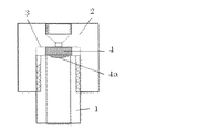
以下、図面に記載した本発明の一態様について説明する。図1は、本発明のフィルターとカラムエンドを示す図である。フィルター4は、シール部材3を介してカラムエンドに組み込まれており、円筒形状のカラム本体1の一端にカラムエンドをねじ込むことでカラム端に圧着固定される。フィルター4の底面(カラムエンド側)は平面(フラット)であるが、その反対の面(カラム充填剤側)4aは、円柱の本体の面上に球体の一部を切り取った突起物を構成した凸状である。この凸状面4aは、カラム端へのカラムフィッティング取り付け時に当該凸状の部分がカラム内に圧入されることで、圧力開放されたカラム中の充填剤を再度加圧し、圧力開放前の高密度に充填された状態を再現する。 Hereinafter, one embodiment of the present invention described in the drawings will be described. FIG. 1 is a view showing a filter and a column end of the present invention. The filter 4 is incorporated into the column end via the seal member 3 and is fixed to the column end by screwing the column end into one end of the cylindrical column main body 1. The bottom surface (column end side) of the filter 4 is a flat surface (flat), but the opposite surface (column filler side) 4a formed a protrusion obtained by cutting off a part of a sphere on the surface of a cylindrical body. Convex shape. The convex surface 4a has a high density before pressure release by pressurizing the packing in the column whose pressure has been released again by pressing the convex part into the column when the column fitting is attached to the column end. Reproduce the state filled in.
図1の例では、カラムは内径が5mm、長さ20mmで、その容積は392μlであり、フィルター4のカラム内部に侵入してその内部空間の一部を占めるフィルター凸状の部分4aは、その容積(カラム内部空間)の3%を占めるように設計してある。 In the example of FIG. 1, the column has an inner diameter of 5 mm, a length of 20 mm, and a volume of 392 μl. The filter convex portion 4 a that penetrates into the column of the filter 4 and occupies a part of its inner space is It is designed to occupy 3% of the volume (column internal space).
本発明のフィルターを用いることにより、例えば内径5mm、長さ40mm程度という小容量のカラムに3μm以下の微粒子を充填する場合などに、いったん圧力開放されたカラム中の充填剤を再度加圧し、圧力開放前の高密度に充填された状態を再現することが可能となる。この結果、微粒子の充填状態の変化に起因するカラム分離性能の変動を抑えることが可能となり、高性能かつ均質なカラムを大量に製造することが可能となる。また実施例に示したように、劣化し難いカラム(耐久性の高いカラム)を提供することも可能となる。しかも本発明は、従来のカラムに適用することが可能である。従って、その実施にあたりコスト的な負担や新たなカラムを製造するといった無駄が発生することもない。 By using the filter of the present invention, for example, when packing fine particles of 3 μm or less into a small-capacity column having an inner diameter of 5 mm and a length of about 40 mm, the pressure in the column once released from the pressure is re-pressurized. It is possible to reproduce the state of being filled with high density before opening. As a result, it is possible to suppress fluctuations in column separation performance due to changes in the packing state of the fine particles, and it is possible to manufacture a high-performance and homogeneous column in large quantities. Further, as shown in the examples, it is possible to provide a column that is not easily deteriorated (a highly durable column). Moreover, the present invention can be applied to conventional columns. Therefore, there is no waste of cost burden and production of a new column in the implementation.
1 液体クロマトグラフィー用カラム
2 カラムエンド
3 シールド部材
4 フィルター
4aフィルターの凸状部
1 Column for liquid chromatography 2 Column end 3 Shield member 4 Filter 4a Convex part of filter
本発明を更に詳細に説明するために実施例を示すが、本発明は実施例に限定されるものではない。 Examples will be shown to describe the present invention in more detail, but the present invention is not limited to the examples.
実施例1
粒子径3μmの非多孔性陽イオン充填剤(1ml)を、内径5mm、長さ20mmのSUS製カラムに50MPaの充填圧力で充填した。カラムエンドは図1に示した形状のもので、SUSフィルター(平面部は直径 5mmの円、1μmの多孔性)は、シール部材(材質 テフロン(登録商標))を介してSUS製カラムエンドに組み込まれており、カラム本体にカラムエンドをねじ込むことでカラム端に圧着固定される。フィルターの底面(カラムエンド側)は平面(フラット)であるが、その反対の面(カラム充填剤側)は、円柱の本体の面上に球体の一部を切り取った突起物(高さ0.8mm)を構成した凸状である。この凸状面は、カラム内部空間の3%を占めるものである。
Example 1
A non-porous cation packing material (1 ml) having a particle size of 3 μm was packed into a SUS column having an inner diameter of 5 mm and a length of 20 mm at a packing pressure of 50 MPa. The column end has the shape shown in FIG. 1, and the SUS filter (the flat portion is a circle with a diameter of 5 mm and a porosity of 1 μm) is incorporated into the column end made of SUS via a seal member (material Teflon (registered trademark)). It is fixed by crimping to the column end by screwing the column end into the column body. The bottom surface (column end side) of the filter is a flat surface (flat), but the opposite surface (column filler side) is a projection (
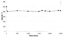
上記カラムを市販のグリコヘモグロビン分析計(商品名HLC−723G9、東ソー株式会社製)に取り付け、溶離液に当該装置用の市販品(G9HSi溶離液1液、G9HSi溶離液2液及びG9HSi溶離液3液、いずれも商品名、東ソー株式会社製)を使用して、人血液中の安定型糖化ヘモグロビン(以下、HbA1cという)を測定した。この時のカラム圧力は約11MPaであった。 The above column was attached to a commercially available glycohemoglobin analyzer (trade name HLC-723G9, manufactured by Tosoh Corporation), and commercial products for the apparatus (G9HSi eluent 1 liquid, G9HSi eluent 2 liquid, and G9HSi eluent 3) were used as the eluent. Using liquids, both trade names, manufactured by Tosoh Corporation), stable glycated hemoglobin (hereinafter referred to as HbA1c) in human blood was measured. The column pressure at this time was about 11 MPa.
カラム耐久性を、HbA1cの分離の目安となるHbA1cピークの理論段数を用いて評価した。結果を図2に示す。0検体測定時の理論段数と2000検体測定時の理論段数を比較すると理論段数の低下は約20%であり、ヘモグロビン類の分離について、充分な耐久性が得られていることが分かる。 Column durability was evaluated using the number of theoretical plates of the HbA1c peak, which is a measure for separating HbA1c. The results are shown in FIG. Comparing the number of theoretical plates at the time of 0 sample measurement and the number of theoretical plates at the time of 2000 sample measurement, the decrease in the number of theoretical plates is about 20%, and it can be seen that sufficient durability is obtained for the separation of hemoglobins.
比較例1
粒子径3μmの非多孔性陽イオン充填剤を、実施例1と同様のカラムに同様の操作を行って充填した。ただし、フィルターとしては実施例1とは異なり、凸状の部分を有していない、円柱状のフィルターを使用した。
Comparative Example 1
A non-porous cation filler having a particle diameter of 3 μm was packed in the same column as in Example 1 by performing the same operation. However, unlike Example 1, as the filter, a cylindrical filter having no convex portion was used.
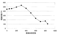
実施例1と同条件でカラム耐久性を評価した結果を図3に示す。カラムの圧力は約11MPaと、実施例1と見かけ上の差はなかったが、0検体測定時の理論段数と850検体測定時の理論段数を比較すると70%以上と著しく低下し、実施例1のカラムと比較して十分な耐久性が得られていないことがわかる。 The results of evaluating column durability under the same conditions as in Example 1 are shown in FIG. The column pressure was about 11 MPa, which was not apparently different from Example 1. However, when the number of theoretical plates at the time of 0 sample measurement and the number of theoretical plates at the time of 850 sample measurement were compared, the column pressure was significantly reduced to 70% or more. It can be seen that sufficient durability is not obtained as compared with the column.
Claims (3)
Priority Applications (1)
| Application Number | Priority Date | Filing Date | Title |
|---|---|---|---|
| JP2013258264A JP6229471B2 (en) | 2013-12-13 | 2013-12-13 | Column for liquid chromatography having a convex filter |
Applications Claiming Priority (1)
| Application Number | Priority Date | Filing Date | Title |
|---|---|---|---|
| JP2013258264A JP6229471B2 (en) | 2013-12-13 | 2013-12-13 | Column for liquid chromatography having a convex filter |
Publications (2)
| Publication Number | Publication Date |
|---|---|
| JP2015114273A true JP2015114273A (en) | 2015-06-22 |
| JP6229471B2 JP6229471B2 (en) | 2017-11-15 |
Family
ID=53528187
Family Applications (1)
| Application Number | Title | Priority Date | Filing Date |
|---|---|---|---|
| JP2013258264A Active JP6229471B2 (en) | 2013-12-13 | 2013-12-13 | Column for liquid chromatography having a convex filter |
Country Status (1)
| Country | Link |
|---|---|
| JP (1) | JP6229471B2 (en) |
Cited By (2)
| Publication number | Priority date | Publication date | Assignee | Title |
|---|---|---|---|---|
| JP7569128B1 (en) | 2024-06-17 | 2024-10-17 | 株式会社巴製作所 | Columns for high performance liquid chromatography (HPLC) and their manufacturing method |
| JP2026047251A (en) * | 2024-08-30 | 2026-03-13 | 株式会社巴製作所 | Method for automatically filling HPLC columns and automatic HPLC column filling apparatus |
Citations (7)
| Publication number | Priority date | Publication date | Assignee | Title |
|---|---|---|---|---|
| JPS63128256A (en) * | 1986-11-19 | 1988-05-31 | Hitachi Ltd | Separation column for high performance liquid chromatography |
| JPH0194260A (en) * | 1987-10-05 | 1989-04-12 | Shimazu Tekunorisaac:Kk | Chromatographic column |
| US5395521A (en) * | 1991-05-31 | 1995-03-07 | Board Of Regents, The University Of Texas System | Automated column equilibration, column loading, column washing and column elution |
| JPH1010106A (en) * | 1996-06-27 | 1998-01-16 | Sekisui Chem Co Ltd | Liquid chromatography filters |
| JP2005521041A (en) * | 2002-03-19 | 2005-07-14 | ウオーターズ・インベストメンツ・リミテツド | Solid phase extraction apparatus and method for purifying a sample before analysis |
| JP2006227022A (en) * | 2006-04-21 | 2006-08-31 | Sekisui Chem Co Ltd | Liquid chromatography filter, liquid chromatography column, and method for measuring hemoglobins |
| JP2011502251A (en) * | 2007-10-31 | 2011-01-20 | アコーニ バイオシステムズ | Sample preparation equipment |
-
2013
- 2013-12-13 JP JP2013258264A patent/JP6229471B2/en active Active
Patent Citations (7)
| Publication number | Priority date | Publication date | Assignee | Title |
|---|---|---|---|---|
| JPS63128256A (en) * | 1986-11-19 | 1988-05-31 | Hitachi Ltd | Separation column for high performance liquid chromatography |
| JPH0194260A (en) * | 1987-10-05 | 1989-04-12 | Shimazu Tekunorisaac:Kk | Chromatographic column |
| US5395521A (en) * | 1991-05-31 | 1995-03-07 | Board Of Regents, The University Of Texas System | Automated column equilibration, column loading, column washing and column elution |
| JPH1010106A (en) * | 1996-06-27 | 1998-01-16 | Sekisui Chem Co Ltd | Liquid chromatography filters |
| JP2005521041A (en) * | 2002-03-19 | 2005-07-14 | ウオーターズ・インベストメンツ・リミテツド | Solid phase extraction apparatus and method for purifying a sample before analysis |
| JP2006227022A (en) * | 2006-04-21 | 2006-08-31 | Sekisui Chem Co Ltd | Liquid chromatography filter, liquid chromatography column, and method for measuring hemoglobins |
| JP2011502251A (en) * | 2007-10-31 | 2011-01-20 | アコーニ バイオシステムズ | Sample preparation equipment |
Cited By (3)
| Publication number | Priority date | Publication date | Assignee | Title |
|---|---|---|---|---|
| JP7569128B1 (en) | 2024-06-17 | 2024-10-17 | 株式会社巴製作所 | Columns for high performance liquid chromatography (HPLC) and their manufacturing method |
| JP2026000335A (en) * | 2024-06-17 | 2026-01-05 | 株式会社巴製作所 | Column for high performance liquid chromatography (HPLC) and its manufacturing method |
| JP2026047251A (en) * | 2024-08-30 | 2026-03-13 | 株式会社巴製作所 | Method for automatically filling HPLC columns and automatic HPLC column filling apparatus |
Also Published As
| Publication number | Publication date |
|---|---|
| JP6229471B2 (en) | 2017-11-15 |
Similar Documents
| Publication | Publication Date | Title |
|---|---|---|
| US8632680B2 (en) | Column for liquid chromatography | |
| US3250395A (en) | Chromatographic columns | |
| US6527951B1 (en) | Chromatographic column | |
| US8147690B2 (en) | Chromatography column | |
| JP4909513B2 (en) | Method for controlling chromatographic columns and absorbent density | |
| DeStefano et al. | Are sub-2 μm particles best for separating small molecules? An alternative | |
| JP6229471B2 (en) | Column for liquid chromatography having a convex filter | |
| CN109030689A (en) | The pre-assembled preparation method of capillary chromatographic column | |
| US11389747B2 (en) | Chromatographic filter | |
| JP2007527536A (en) | Frit for high pressure liquid chromatography | |
| JP5620480B2 (en) | Piston motion control for a tuned chromatography column | |
| JP2010066057A (en) | Connector for capillary column | |
| CN105973683A (en) | Pretreatment device as well as use method and application thereof | |
| CN205826387U (en) | A kind of pretreating device | |
| JP2007040999A (en) | Column with tapered intermediate piece | |
| Franc et al. | Performance and lifetime of slurry packed capillary columns for high performance liquid chromatography | |
| JP7288819B2 (en) | Columns, chromatograph equipment | |
| US20190030457A1 (en) | Packed bed | |
| DE68924284T2 (en) | High pressure liquid chromatography column. | |
| US20150338383A1 (en) | Frits for Chromatography | |
| US20140260534A1 (en) | Biocompatible Filter | |
| US9267927B2 (en) | Robust and low backpressure on-column tunneled frit for nano-UPLC-MS applications | |
| JP4933457B2 (en) | Double-chamber chromatograph cartridge | |
| JP2026000335A (en) | Column for high performance liquid chromatography (HPLC) and its manufacturing method | |
| JP2021049503A (en) | Liquid chromatograph, separation column, and filler of separation column |
Legal Events
| Date | Code | Title | Description |
|---|---|---|---|
| A621 | Written request for application examination |
Free format text: JAPANESE INTERMEDIATE CODE: A621 Effective date: 20161122 |
|
| A131 | Notification of reasons for refusal |
Free format text: JAPANESE INTERMEDIATE CODE: A131 Effective date: 20170704 |
|
| A977 | Report on retrieval |
Free format text: JAPANESE INTERMEDIATE CODE: A971007 Effective date: 20170630 |
|
| A521 | Request for written amendment filed |
Free format text: JAPANESE INTERMEDIATE CODE: A523 Effective date: 20170808 |
|
| TRDD | Decision of grant or rejection written | ||
| A01 | Written decision to grant a patent or to grant a registration (utility model) |
Free format text: JAPANESE INTERMEDIATE CODE: A01 Effective date: 20170919 |
|
| A61 | First payment of annual fees (during grant procedure) |
Free format text: JAPANESE INTERMEDIATE CODE: A61 Effective date: 20171002 |
|
| R151 | Written notification of patent or utility model registration |
Ref document number: 6229471 Country of ref document: JP Free format text: JAPANESE INTERMEDIATE CODE: R151 |