JP2015114603A - Toner storing container, toner refilling device, and image formation device - Google Patents
Toner storing container, toner refilling device, and image formation device Download PDFInfo
- Publication number
- JP2015114603A JP2015114603A JP2013258206A JP2013258206A JP2015114603A JP 2015114603 A JP2015114603 A JP 2015114603A JP 2013258206 A JP2013258206 A JP 2013258206A JP 2013258206 A JP2013258206 A JP 2013258206A JP 2015114603 A JP2015114603 A JP 2015114603A
- Authority
- JP
- Japan
- Prior art keywords
- toner
- storage container
- toner storage
- cover
- screw
- Prior art date
- Legal status (The legal status is an assumption and is not a legal conclusion. Google has not performed a legal analysis and makes no representation as to the accuracy of the status listed.)
- Granted
Links
Images
Landscapes
- Dry Development In Electrophotography (AREA)
Abstract
【課題】トナー凝集体の生成を抑制しつつトナーの収納容量を増加できるトナーカートリッジを提供する。【解決手段】トナーカートリッジ50は、トナー収納部52と、撹拌部材58と、撹拌部材58によって撹拌されたトナーを、現像装置に補給するための排出口に向けて搬送する搬送スクリュ56とを備えている。搬送スクリュ56は撹拌部材58の回転半径Rの内側に一部が入るように配置されている。これにより、図6(a)に示す従来構成に比べて、符号88で示す分、トナー収納容量を増やすことができる。搬送スクリュ56の軸方向両端部は図示しないカバーで覆われており、搬送スクリュ56の露出した部分が撹拌部材58と接触することはなく、接触ストレスによるトナーの凝集化も抑制される。【選択図】図6A toner cartridge capable of increasing toner storage capacity while suppressing generation of toner aggregates is provided. A toner cartridge includes a toner storage section, a stirring member, and a transport screw that transports the toner stirred by the stirring member toward a discharge port for replenishing the developing device. ing. The conveying screw 56 is arranged so that a part thereof is inside the rotation radius R of the stirring member 58. Thereby, compared with the conventional configuration shown in FIG. 6A, the toner storage capacity can be increased by the amount indicated by reference numeral 88. Both ends of the conveying screw 56 in the axial direction are covered with a cover (not shown), and the exposed portion of the conveying screw 56 does not come into contact with the stirring member 58, and aggregation of toner due to contact stress is suppressed. [Selection] Figure 6
Description
本発明は、トナー収納容器、該トナー収納容器を着脱自在に支持するトナー補給装置、該トナー補給装置を有する複写機、プリンタ、ファクシミリ、プロッタ、あるいはこられのうち少なくとも1つを備えた複合機等の画像形成装置に関する。 The present invention relates to a toner storage container, a toner replenishing device that detachably supports the toner storage container, a copying machine having the toner replenishing device, a printer, a facsimile machine, a plotter, or a multifunction machine including at least one of these. The present invention relates to an image forming apparatus.
この種の電子写真方式による画像形成装置では、像担持体上の静電潜像に現像装置で現像剤としてのトナーを供給することで、静電潜像をトナー像として可視像化している。
現像装置内のトナーは使用に伴い消費されて少なくなるため、画像形成装置には、現像装置にトナーを補給するためのトナー補給装置が備えられている。
トナー補給装置は、トナー収納容器と、該トナー収納容器を着脱可能に装着する装着部とを備えている。
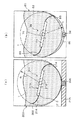
図6(a)に示すように、トナー収納容器200は、トナーTを収納するためのトナー収納部202と、トナーを外部に排出するための図示しない排出口と、トナー収納部202内のトナーを排出口に搬送するトナー搬送手段204とを有している。
後述する現像装置内のトナー量が減少したことが図示しないトナー濃度センサにより検知されると、トナー搬送手段204が駆動され、トナー収納部202内のトナーが排出口から排出されて現像装置へ供給される。
In this type of electrophotographic image forming apparatus, the electrostatic latent image is visualized as a toner image by supplying toner as a developer to the electrostatic latent image on the image carrier with a developing device. .
Since the toner in the developing device is consumed and reduced with use, the image forming apparatus is provided with a toner replenishing device for replenishing the developing device with toner.
The toner replenishing device includes a toner storage container and a mounting portion that detachably mounts the toner storage container.
As shown in FIG. 6A, the
When a toner density sensor (not shown) detects that the amount of toner in the developing device, which will be described later, has decreased, the toner transport unit 204 is driven, and the toner in the
トナー搬送手段204は、回転しながら排出口に向けてトナーを搬送するトナー排出部材としての搬送スクリュ206と、搬送スクリュ206によるトナー搬送方向と直交する方向に回転し、トナーを攪拌しながら搬送スクリュへ供給する撹拌部材208とから構成されている。
攪拌部材208は、回転軸210を一体に有する比較的高剛性の支持部材212と、支持部材212の自由端側に配置された可撓性の羽根部材214とを備えている。
支持部材212が回転すると、羽根部材214がトナー収納部202の内壁に接触して弾性変形した状態で移動する。これによりトナーは撹拌されながら搬送スクリュ206の部位へ供給される。
排出口は、搬送スクリュ206の軸方向一端側に形成されており、搬送スクリュ206の回転により搬送されたトナーは排出口からトナー収納容器200の外部に落下する。
The toner conveying means 204 rotates in a direction perpendicular to the toner conveying direction by the conveying
The
When the
The discharge port is formed on one end side in the axial direction of the
搬送スクリュ206と羽根部材214とが接触すると、トナーにストレスが加わり、トナー凝集体が生成しやすい。
トナー凝集体が生じると、塊状のまま現像装置へ補給され、現像装置内での現像剤の流動性を阻害し、トナーの均一帯電にも悪影響を及ぼす。
このような問題を回避すべく、搬送スクリュ206は、攪拌部材208と接触しないように、攪拌部材208の回転半径Rの領域の外側に配置されている。
ここでの回転半径Rは、羽根部材214がトナー収納部202の内壁に接触して弾性変形した状態で移動する場合の軌跡円の半径を意味し、換言すれば、トナー収納部202の下部の円弧状の曲率半径である(以下、同じ)。
When the conveying
When toner aggregates are formed, they are replenished to the developing device in the form of lumps, impeding the flowability of the developer in the developing device and adversely affecting the uniform charging of the toner.
In order to avoid such a problem, the conveying
Here, the rotation radius R means the radius of the locus circle when the
このため、トナー収納容器200の下部には、搬送スクリュ206の存在によって、ハッチングで示すデッドスペース216が生じ、トナー収納容器全体におけるトナー収納容量を低下させていた。
換言すれば、トナー収納容器全体の容積に占めるトナー容量の割合を増やすことができず、搬送スクリュ206の存在によって生じるスペースが無駄となっていた。
For this reason, a
In other words, the ratio of the toner capacity to the total volume of the toner container cannot be increased, and the space generated by the presence of the conveying
トナー収納容器のトナー収納容量は、トナーが空になった場合の交換作業の頻度を低減する観点からもできるだけ大きい方が望ましい。 The toner storage capacity of the toner storage container is desirably as large as possible from the viewpoint of reducing the frequency of replacement work when the toner becomes empty.
本発明は、このような現状に鑑みて創案されたもので、トナー凝集体の生成を抑制しつつトナーの収納容量を増加できるトナー収納容器の提供を、その主な目的とする。 The present invention has been made in view of such a current situation, and its main object is to provide a toner storage container capable of increasing the storage capacity of toner while suppressing the formation of toner aggregates.
上記目的を達成するために、本発明は、トナーを収納するためのトナー収納部と、前記トナー収納部に収納されているトナーを排出するための排出口と、前記トナー収納部内のトナーを前記排出口に搬送するトナー搬送手段と、を有し、前記トナー搬送手段は、回転しながら前記排出口に向けてトナーを搬送するトナー排出部材と、該トナー排出部材によるトナー搬送方向と交差する方向に回転し、トナーを攪拌しながら前記トナー排出部材へ供給するための撹拌部材とで構成されたトナー収納容器において、前記トナー排出部材は、少なくともその一部が前記撹拌部材の回転半径の内側に位置するように配置され、前記トナー排出部材の一部がカバーで覆われ、前記撹拌部材が前記カバーに接触して変形することで、前記トナー排出部材を乗り越えながら回転することを特徴とする。 To achieve the above object, the present invention provides a toner storage portion for storing toner, a discharge port for discharging the toner stored in the toner storage portion, and the toner in the toner storage portion. A toner conveying unit that conveys the toner toward the discharge port, and a toner discharge member that conveys the toner toward the discharge port while rotating, and a direction that intersects a toner conveyance direction by the toner discharge member And a stirring member for supplying the toner to the toner discharge member while stirring the toner. At least a part of the toner discharge member is located inside the rotation radius of the stirring member. A portion of the toner discharge member is covered with a cover, and the stirring member is deformed in contact with the cover so that the toner discharge member is Characterized in that it rotates Rikoe.
本発明によれば、トナー凝集体の生成を抑制しつつトナーの収納容量を増加できるトナー収納容器を実現できる。
これにより、トナー収納容器の交換頻度の抑制に寄与することができる。
According to the present invention, it is possible to realize a toner storage container capable of increasing the toner storage capacity while suppressing the formation of toner aggregates.
Thereby, it can contribute to suppression of the replacement frequency of a toner storage container.
以下、本発明の一実施形態を図を参照して説明する。
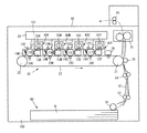
図1に基づいて、本実施形態に係る画像形成装置としてのカラープリンタ(以下、単に「プリンタ」という)の構成の概要を説明する。
このプリンタは、イエロー、シアン、マゼンタ、ブラックの4色の現像剤を用いてカラー画像を形成するものである。
図中、符号の末尾に付すY、C、M、Kという添字は、イエロー、シアン、マゼンタ、ブラック用の部材であることを示す。なお、同一の機能及び同一の部材には同一の符号を付し、重複説明は省略する。
Hereinafter, an embodiment of the present invention will be described with reference to the drawings.
An outline of the configuration of a color printer (hereinafter simply referred to as “printer”) as an image forming apparatus according to the present embodiment will be described with reference to FIG.
This printer forms a color image using four color developers of yellow, cyan, magenta, and black.
In the figure, the suffixes Y, C, M, and K attached to the end of the reference numerals indicate members for yellow, cyan, magenta, and black. In addition, the same code | symbol is attached | subjected to the same function and the same member, and duplication description is abbreviate | omitted.
プリンタは、その本体100の内部に、転写手段として転写ユニット20を備えている。転写ユニット20は、複数のローラ21、22に、中間転写体としての無端状の中間転写ベルト23を巻きかけた構成を有している。
中間転写ベルト23は、図示しない駆動モータによって図中反時計回り方向に回転移動する。
中間転写ベルト23の内側には、1次転写部材としての4つの1次転写ローラ24Y、24C、24M、24Kがベルトに接するように配置されている。
中間転写ベルト23の外側には、ローラ21と対向する位置に2次転写部材としての2次転写ローラ25が配置されている。
符号26は、中間転写ベルト23の表面を清掃するベルトクリーニング手段を示している。
The printer includes a
The
Inside the
A
1次転写ローラ24Y、24C、24M、24Kには、図示しない電源から1次転写バイアスが供給され、2次転写ローラ25には、2次転写バイアスが図示しない電源から供給される。
転写ユニット20の上方には、作像手段としてY、C、M、K用の4つの画像形成ユニットが、中間転写ベルト23の上部水平面に沿って配設されている。
A primary transfer bias is supplied from a power source (not shown) to the
Above the
各画像形成ユニットは、像担持体としてのドラム状の感光体11Y、11C、11M、11Kと、帯電手段12Y、12C、12M、12Kと、現像装置13Y、13C、13M、13Kとを備えている。
また、各画像形成ユニットは、ドラムクリーニング装置14Y、14C、14M、14Kをそれぞれ備えている。
これら各部材は、図示しないケーシングによってユニット毎に一体化されていて、本体100に対して着脱自在となっている。
各感光体の周面の下部は、1次転写ローラ24Y、24C、24M、24Kと対向する中間転写ベルト23の上部水平面に当接しており、これによりY、C、M、K用の1次転写ニップが形成されている。
Each image forming unit includes drum-
Each image forming unit includes
These members are integrated for each unit by a casing (not shown) and are detachable from the
The lower part of the peripheral surface of each photoconductor is in contact with the upper horizontal surface of the
画像形成ユニットの上方には書込ユニット30が配置されている。書込ユニット30は、画像情報に基づいて図示しない光源を駆動してY、C、M、K用の露光光を各感光体に照射して光走査することで、図中時計回り方向に回転駆動する各感光体の周面に静電潜像を形成する。
現像装置13Y、13C、13M、13Kには、それぞれY、C、M、K色の現像剤が収納されていて、現像バイアスが供給される現像剤担持体によって、それぞれの現像剤が各感光体表面に供給される。
これにより、静電潜像が現像されてトナー像として可視像化される。
現像装置13Y、13C、13M、13Kの上部には、トナー補給装置40Y、40C、40M、40Kが配置されている。
トナー補給装置40Y、40C、40M、40Kには、補給用のトナーが収納されたトナー収納容器としてのトナーカートリッジ50Y、50C、50M、50が着脱可能に装着されている。
A
The developing
As a result, the electrostatic latent image is developed and visualized as a toner image.
現像装置13Y、13C、13M、13Kには、図示しないトナー濃度センサが設けられており、トナー濃度センサにより現像剤中のトナー濃度が所定値を下回ったことがと検知されると、図示しない制御手段はトナー補給装置40Y、40C、40M、40Kを作動させる。
これにより、トナーカートリッジ50Y、50C、50M、50内のトナーが図示しないトナー補給手段により現像装置へ補給される。
The developing
As a result, the toner in the
転写ユニット20の下方には、記録媒体としての記録材Pが収納された給紙部60が配置されている。
給紙部60の記録材Pは、給紙ローラ61によって給紙部60から給紙経路62へ送り出される。給紙経路62には、給紙部60から送り出された記録材Pを2次転写ニップに向けて搬送する搬送ローラ対63と、レジストローラ対64が配置されている。
給紙経路62の記録材Pは、レジストローラ対64によって、中間転写ベルト23上の重ね合わせ画像とタイミングを合わせて2次転写ニップに搬送される。
二次転写ニップよりも装置上方には、定着手段70が配置されていて、定着手段70よりも記録材の搬送方向下流側には、排紙ローラ対65が配置されている。
Below the
The recording material P of the
The recording material P in the
A fixing
カラー画像形成時には、各色の感光体表面に形成されたトナー像が、1次転写ニップにおいて中間転写ベルト23上に重ね合わせて転写され、重ね合わせ画像が2次転写ニップにおいて記録材Pに一括転写される。
転写後の各感光体はドラムクリーニング装置14Y、14C、14M、14Kによって、転写後の中間転写ベルト23はベルトクリーニング手段26によって、それぞれその表面に残留している現像剤や紙粉などを除去される。
重ね合わせ画像を転写された記録材Pは定着手段70を通過することでトナー像が定着され、排紙ローラ対65によって本体100の外部に排出される。
本実施形態では、記録材Pは本体上面に形成された積載部66にスタックされる。
At the time of color image formation, the toner image formed on the surface of the photoconductor of each color is transferred onto the
Each transferred photoreceptor is removed by
The recording material P to which the superimposed image is transferred passes through the fixing
In the present embodiment, the recording material P is stacked on a stacking
次にトナー補給装置とトナーカートリッジの構成について説明する。
トナー補給装置40Y、40C、40M、40Kと、トナーカートリッジ50Y、50C、50M、50Kは、現像剤(トナー)の色が異なる以外は同一構成であるので、共通の構成としてその1つを以下に説明する。なお、添字であるY、C、M、Kは省略する。
Next, the configuration of the toner supply device and the toner cartridge will be described.
Since the
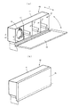
図2に示すように、トナー補給装置40は、トナーカートリッジ50と、トナーカートリッジ50を着脱可能に支持する装着部41とを備えていて、トナーカートリッジ50内のトナーを、対応する色の現像装置13に供給するものである。
装着部41は、その内部にトナーカートリッジ50を収納するための開口42と、開口42を開閉するドア43とを有している。
装着部41は、その内部形状がトナーカートリッジ50の外観形状と近似する形状を有し、符号Aで示す方向に着脱自在にトナーカートリッジ50を保持する。
符号A1は挿入方向、符号A2は離脱方向をそれぞれ示す。
As shown in FIG. 2, the
The mounting
The mounting
Reference symbol A1 indicates an insertion direction, and reference symbol A2 indicates a removal direction.
図2(a)は、4つのトナーカートリッジ50をそれぞれ収納する開口42が形成された構成を示している。
また、1つのトナーカートリッジ50が装着部41に収納され、ドア43が開いている状態を示している。
図2(b)は、ドア43を閉じた状態を示していて、この状態において開口42は塞がれている。ドア43は、画像形成装置の本体100の外装面に位置していて、本体100の外部側から開閉操作可能となっている。
FIG. 2A shows a configuration in which
In addition, one
FIG. 2B shows a state in which the
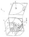
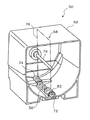
トナーカートリッジ50は、図3に示すように、前面が開口された容器本体としてのトナー収納部52と、前面を塞ぐ側板としての前板54とから構成されている。
トナー収納部52には、トナー収納部52内に収納されたトナーを回転しながら図示しない排出口に向けて搬送するトナー排出部材としての搬送スクリュ56と、トナー収納部52内のトナーを撹拌しながら搬送スクリュ56の部位へ供給する撹拌部材58とが備えられている。
搬送スクリュ56はトナー収納部52の底面側に一体に形成された断面が半円状のトナー搬送路72に収容されており、図示しない駆動機構により回転する。
搬送スクリュ56のトナー搬送方向(以下、「軸方向」又は「回転軸方向」という)における上流側端部は、トナー収納部52に一体に形成されたカバーとしての後部スクリュカバー74で覆われている。
トナー搬送路72の軸方向下流側に上記排出口が設けられており、搬送スクリュ56で搬送されたトナーは該排出口から落下して図示しないトナー補給手段により現像装置へ補給される。
As shown in FIG. 3, the
The
The conveying
The upstream end of the conveying
The discharge port is provided on the downstream side in the axial direction of the
撹拌部材58は、上記軸方向における端部がトナー収納部52に片持ち状態で支持された回転軸76と、撹拌部材本体78とから構成されている。
撹拌部材58は、搬送スクリュ56による軸方向と交差する方向、ここでは直交する方向に回転する。
トナー補給装置40にトナーカートリッジ50をセットすると、トナー補給装置40側に設けられた図示しない駆動機構に回転軸76が回転駆動可能に連結される。搬送スクリュ56においても同様である。
前板54の内側には、回転軸76の自由端部を挿入して支持するための軸受80が一体成形されている。
また、トナー収納部52の前面を塞ぐように前板54を取り付けたときに、搬送スクリュ56の軸方向における下流側端部の上部を覆うカバーとしての前部スクリュカバー82が一体に形成されている。
The stirring
The agitating
When the
Inside the
Further, when the
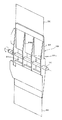
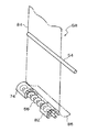
前板54を取り付けると、図4に示すように、搬送スクリュ56の回転軸方向における両端部はそれぞれ、後部スクリュカバー74と前部スクリュカバー82とにより覆われ、それらの間は搬送スクリュ56が露出した状態となる。
When the
図5に基づいて、撹拌部材58の構成を詳細に説明する。
撹拌部材本体78は、トナーがすり抜ける開口84aやリブ84bを有し、回転軸76に一体に固定される骨部材84と、骨部材84の両端部に固定された可撓性を有する羽根部材86とから構成されている。骨部材84は剛性を有している。
撹拌部材58の回転軸76と搬送スクリュ56は、トナー収納部52に、互いに平行になるように配置されている。
Based on FIG. 5, the structure of the stirring
The agitating member
The rotating
撹拌部材58は、トナー収納部52内のトナーが塊状になるのを防ぐように攪拌し、且つ、トナーを搬送スクリュ56が配置されたトナー搬送路72に供給する。
トナー搬送路72に供給されたトナーは搬送スクリュ56によってその軸方向に搬送され、上記排出口から排出され、トナーカートリッジの下に配置される図示しないサブホッパに入る。
上記排出口は図示しないシャッタ部材により開閉可能となっている。トナー補給時には排出口が開放される。
本実施形態ではトナーカートリッジから排出されたトナーをトナー補給手段で現像装置へ搬送する構成としたが、トナーカートリッジから現像装置に直接供給する構成としてもよい。
The agitating
The toner supplied to the
The discharge port can be opened and closed by a shutter member (not shown). When toner is supplied, the discharge port is opened.
In this embodiment, the toner discharged from the toner cartridge is transported to the developing device by the toner replenishing means. However, the toner cartridge may be directly supplied to the developing device.
回転軸76と骨部材84は、金属や樹脂などで一体的に形成するのが簡便で好ましい。他の材料や製造方法で形成してもよい。
羽根部材86は、剛性の低い材質、例えばPET(ポリエチレンテレフタレート)または、PE(ポリエチレン)、PP(ポリプロピレン)、PPS(ポリフェニレンサルファイド)、ポリウレタンシート等可撓性を有する部材からなる。
羽根部材86の厚さは50μm〜500μm程度が好ましく、特に50μm〜300μmが好適である。
羽根部材86は、回転軸76に直交する方向における骨部材84の端から外側に10mm以上延びる長さに設定されている。
羽根部材86のトナー収納部52の壁面(内面)への食い込み量は0〜20mm程度が好ましい。
It is simple and preferable that the rotating
The
The thickness of the
The
The amount of biting into the wall surface (inner surface) of the
図6(b)に示すように、本実施形態における搬送スクリュ56は、撹拌部材58の回転半径Rの内側に一部が入り込む位置に配置されている。
このように配置することで、トナー収納部52の容積を符号88で示す分増やすことができる。換言すれば、トナー収納部52の底面を下げて容積を大きくすることができる。
このようにした場合、搬送スクリュ56と羽根部材86とが接触し、上述したように、トナーにストレスが加わり、トナー凝集体が生成しやすくなる。
As shown in FIG. 6B, the conveying
By disposing in this way, the volume of the
In such a case, the conveying
しかしながら、上記のように搬送スクリュ56の軸方向両端部はそれぞれ、後部スクリュカバー74と前部スクリュカバー82とで覆われている。
このため、図7及び図8に示すように、羽根部材86はその軸方向端部が後部スクリュカバー74と前部スクリュカバー82とに接触して撓む。
羽根部材86は軸方向に切れ目の無い長方形状であるため、羽根部材86の中央部もそれに追随して撓む。
However, as described above, both end portions in the axial direction of the conveying
For this reason, as shown in FIGS. 7 and 8, the
Since the
このため、羽根部材86は、後部スクリュカバー74と前部スクリュカバー82との間に露出する搬送スクリュ56に接触することなく、搬送スクリュ56を乗り越えて移動する。
したがって、搬送スクリュ56と羽根部材86とが接触してトナー凝集体が生成するのを抑制することができる。
撹拌部材58により供給されたトナーは、搬送スクリュ56の露出した部分で排出口へ向けて搬送される。
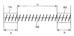
図9に示すように、搬送スクリュ56のカバーで覆われる長さ(a+b)よりも、カバー間の露出する長さcを大きくするのが望ましい。これによりトナーの排出性を確保できる。
Therefore, the
Accordingly, it is possible to suppress the toner aggregates from being generated due to contact between the conveying
The toner supplied by the stirring
As shown in FIG. 9, it is desirable to make the exposed length c between the covers larger than the length (a + b) covered with the cover of the
なお、図7、図8では、説明を分かりやすくするために、撹拌部材58の回転方向を実際(反時計周り方向)とは逆態様で示している。
流出温度が90℃以下のトナーを用いる場合には、特に凝集が生じやすいが、このようなトナーでも本実施形態の構成によれば、トナー凝集体が生成するのを良好に抑制することができる。
In FIGS. 7 and 8, the rotation direction of the stirring
When toner having an outflow temperature of 90 ° C. or less is used, aggregation is particularly likely to occur. However, according to the configuration of the present embodiment, it is possible to satisfactorily suppress the formation of toner aggregates even with such toner. .
上記のように本実施形態では、前部スクリュカバー82を前板54に一体に形成している。このようにすれば、トナー収納部52に一体に形成する場合に比べ、型による成形時の抜き等の問題を回避可能である。
勿論、前部スクリュカバー82をトナー収納部52に一体に形成してもよい。また、後部スクリュカバー74を後板に一体に形成してもよい。
要するに、トナー収納部52を構成すべく、前板54等の側板を組み付けたとき、あるいは開閉可能な側板を閉めたときに、搬送スクリュ56の軸方向端部がカバーで覆われる構成となればよい。
また、後部スクリュカバー74と前部スクリュカバー82をトナー搬送路72と一体に円筒状に形成してもよい。
As described above, in this embodiment, the
Of course, the
In short, when the side plate such as the
Further, the
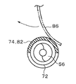
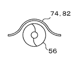
本実施形態では、後部スクリュカバー74と前部スクリュカバー82の断面形状を半円状としたが、図10に示すように、外側に向かってなだらかに湾曲する山形状とすれば、カバー部位におけるトナーの留まりを抑制でき、一層望ましい。
また、上記では羽根部材86が搬送スクリュ56の露出部分に接触しない構成としたが、トナー凝集体の生成を抑制できる程度の接触状態であれば接触しても問題はない。
接触しないようにすることが最も望ましいが、羽根部材86が搬送スクリュ56に接触する、しないにかかわらず、カバーによってトナー凝集体の生成を抑制できればよいというのが本発明の趣旨である。
この抑制機能が得られるように、羽根部材86の軸方向の長さは、図9におけるカバー間の露出長さcよりも大きく設定されている。
In the present embodiment, the cross-sectional shapes of the
In the above description, the
Although it is most desirable not to contact, the gist of the present invention is that it is only necessary to suppress the generation of toner aggregates by the cover regardless of whether or not the
In order to obtain this suppression function, the axial length of the
上記実施形態では、搬送スクリュ56の軸方向における両端部をカバーで覆う構成としたが、羽根部材86の搬送スクリュ56に対する接触を回避ないし低減できれば、一方のみでもよい。
また、上記実施形態では、トナー排出部材としてスクリュ形状を採用した構成を例示したが、これに限定されず、例えば搬送コイル等でもよい。
In the above embodiment, the both ends of the conveying
Further, in the above-described embodiment, the configuration in which the screw shape is adopted as the toner discharge member is illustrated, but the present invention is not limited thereto, and for example, a conveyance coil may be used.
特許文献1には、撹拌部材の回転半径内に搬送スクリュを設置する構成が記載されているが、搬送スクリュの上方にトナーのケーキ状の塊ができることを防止するために、搬送スクリュに積極的に撹拌部材を接触させることを目的としている。
その接触が確実に生じるように、同文献の図7に示すように、羽根部材には軸方向に間隔をおいて複数のスリットが形成されている。
このような構成では、搬送スクリュと羽根部材とが接触してトナー凝集体が生成するのを抑制することができない。
また、羽根部材がスリット(切れ目)を有する構成では、カバーに接触したときの羽根部材の中央部の、搬送スクリュへの接触を回避する変形追従性は得られない。
Patent Document 1 describes a configuration in which a conveyance screw is installed within the rotation radius of a stirring member. However, in order to prevent the formation of a cake-like lump of toner above the conveyance screw, the conveyance screw is actively used. It aims at making a stirring member contact.
As shown in FIG. 7 of the document, a plurality of slits are formed in the blade member at intervals in the axial direction so that the contact is surely generated.
With such a configuration, it is not possible to prevent the toner aggregates from being generated due to contact between the conveying screw and the blade member.
Further, in the configuration in which the blade member has a slit (cut), the deformation follow-up property that avoids the contact of the central portion of the blade member with the conveying screw when contacting the cover cannot be obtained.
11 像担持体としての感光体
13 現像装置
40 トナー補給装置
41 装着部
50 トナー収納容器としてのトナーカートリッジ
52 トナー収納部
54 側板としての前板
56 トナー排出部材としての搬送スクリュ
58 撹拌部材
74 カバーとしての後部スクリュカバー
82 カバーとしての前部スクリュカバー
DESCRIPTION OF SYMBOLS 11 Photoconductor as image carrier 13 Developing
Claims (7)
前記トナー収納部に収納されているトナーを排出するための排出口と、
前記トナー収納部内のトナーを前記排出口に搬送するトナー搬送手段と、
を有し、
前記トナー搬送手段は、回転しながら前記排出口に向けてトナーを搬送するトナー排出部材と、該トナー排出部材によるトナー搬送方向と交差する方向に回転し、トナーを攪拌しながら前記トナー排出部材へ供給するための撹拌部材とで構成されたトナー収納容器において、
前記トナー排出部材は、少なくともその一部が前記撹拌部材の回転半径の内側に位置するように配置され、
前記トナー排出部材の一部がカバーで覆われ、
前記撹拌部材が前記カバーに接触して変形することで、前記トナー排出部材を乗り越えながら回転することを特徴とするトナー収納容器。 A toner storage section for storing toner;
A discharge port for discharging the toner stored in the toner storage unit;
Toner conveying means for conveying the toner in the toner storage portion to the discharge port;
Have
The toner conveying means rotates in a direction that intersects a toner conveying direction by the toner discharging member and conveys the toner toward the discharging port while rotating, to the toner discharging member while stirring the toner. In a toner storage container composed of a stirring member for supplying,
The toner discharging member is disposed so that at least a part thereof is located inside the rotation radius of the stirring member,
A portion of the toner discharge member is covered with a cover;
A toner storage container, wherein the agitating member rotates while getting over the toner discharging member when the stirring member comes into contact with the cover and deforms.
前記カバーが、前記撹拌部材の回転軸方向における前記トナー排出部材の両端部に設けられていることを特徴とするトナー収納容器。 The toner container according to claim 1.
The toner storage container, wherein the cover is provided at both ends of the toner discharge member in the rotation axis direction of the stirring member.
前記カバーが前記トナー収納部を構成する側板に設けられ、前記側板を組み付けたとき、あるいは閉めたときに前記カバーが前記トナー排出部材を覆うことを特徴とするトナー収納容器。 The toner storage container according to claim 2.
A toner storage container, wherein the cover is provided on a side plate constituting the toner storage portion, and the cover covers the toner discharge member when the side plate is assembled or closed.
前記カバーが前記側板に一体成形されていることを特徴とするトナー収納容器。 The toner storage container according to claim 3.
A toner storage container, wherein the cover is integrally formed with the side plate.
前記トナー排出部材がスクリュ形状を有していることを特徴とするトナー収納容器。 In the toner storage container according to any one of claims 1 to 4,
A toner storage container, wherein the toner discharge member has a screw shape.
前記トナー収納容器が請求項1〜5のいずれか1つに記載のトナー収納容器であることを特徴とするトナー補給装置。 A toner replenishing device that includes a toner storage container and a mounting portion that detachably supports the toner storage container, and supplies toner in the toner storage container to a developing device;
A toner supply device, wherein the toner storage container is the toner storage container according to claim 1.
前記トナー補給装置が請求項6に記載のトナー補給装置であることを特徴とする画像形成装置。 An image forming apparatus comprising: an image carrier; a developing device that visualizes an electrostatic latent image formed on the image carrier; and a toner replenishing device that supplies toner to the developing device.
An image forming apparatus, wherein the toner supply device is the toner supply device according to claim 6.
Priority Applications (1)
| Application Number | Priority Date | Filing Date | Title |
|---|---|---|---|
| JP2013258206A JP6252155B2 (en) | 2013-12-13 | 2013-12-13 | Toner container, toner supply device, and image forming apparatus |
Applications Claiming Priority (1)
| Application Number | Priority Date | Filing Date | Title |
|---|---|---|---|
| JP2013258206A JP6252155B2 (en) | 2013-12-13 | 2013-12-13 | Toner container, toner supply device, and image forming apparatus |
Publications (2)
| Publication Number | Publication Date |
|---|---|
| JP2015114603A true JP2015114603A (en) | 2015-06-22 |
| JP6252155B2 JP6252155B2 (en) | 2017-12-27 |
Family
ID=53528427
Family Applications (1)
| Application Number | Title | Priority Date | Filing Date |
|---|---|---|---|
| JP2013258206A Active JP6252155B2 (en) | 2013-12-13 | 2013-12-13 | Toner container, toner supply device, and image forming apparatus |
Country Status (1)
| Country | Link |
|---|---|
| JP (1) | JP6252155B2 (en) |
Citations (4)
| Publication number | Priority date | Publication date | Assignee | Title |
|---|---|---|---|---|
| JP2008197636A (en) * | 2007-01-15 | 2008-08-28 | Kyocera Mita Corp | Toner container |
| JP2010020227A (en) * | 2008-07-14 | 2010-01-28 | Canon Inc | Developer supply device and electrophotographic image forming device |
| JP2013122511A (en) * | 2011-12-09 | 2013-06-20 | Canon Inc | Cartridge and image forming apparatus |
| JP2013160795A (en) * | 2012-02-01 | 2013-08-19 | Ricoh Co Ltd | Developer container, developing device, process unit, and image forming apparatus |
-
2013
- 2013-12-13 JP JP2013258206A patent/JP6252155B2/en active Active
Patent Citations (4)
| Publication number | Priority date | Publication date | Assignee | Title |
|---|---|---|---|---|
| JP2008197636A (en) * | 2007-01-15 | 2008-08-28 | Kyocera Mita Corp | Toner container |
| JP2010020227A (en) * | 2008-07-14 | 2010-01-28 | Canon Inc | Developer supply device and electrophotographic image forming device |
| JP2013122511A (en) * | 2011-12-09 | 2013-06-20 | Canon Inc | Cartridge and image forming apparatus |
| JP2013160795A (en) * | 2012-02-01 | 2013-08-19 | Ricoh Co Ltd | Developer container, developing device, process unit, and image forming apparatus |
Also Published As
| Publication number | Publication date |
|---|---|
| JP6252155B2 (en) | 2017-12-27 |
Similar Documents
| Publication | Publication Date | Title |
|---|---|---|
| JP5220874B2 (en) | Developer storage container and image forming apparatus | |
| JP5740324B2 (en) | Developer container and image forming apparatus to which the container is applied | |
| US8290407B2 (en) | Toner supply apparatus with a drive member for driving an agitator and with a film covering the periphery of the drive member | |
| CN104142615A (en) | Toner cartridge and image forming apparatus | |
| KR101457759B1 (en) | Developer container and image forming device equipped with the same | |
| CN102193395B (en) | Powder transporting unit and image forming apparatus using the same | |
| JP6620700B2 (en) | Developer container and image forming apparatus having the same | |
| JP2013037285A (en) | Shutter opening and closing mechanism, and developer storage container, and image forming apparatus | |
| JP5476695B2 (en) | Developing device, process cartridge, and image forming apparatus | |
| JP2018017749A (en) | Toner container and image forming apparatus | |
| EP2687914B1 (en) | Developer conveying device, and developing device and image forming apparatus provided with same | |
| JP6252155B2 (en) | Toner container, toner supply device, and image forming apparatus | |
| JP6555207B2 (en) | Image forming apparatus and toner container mounted on image forming apparatus | |
| JP5619246B2 (en) | Developer container and image forming apparatus to which the container is applied | |
| JP6079187B2 (en) | Powder supply device and image forming apparatus | |
| JP5365375B2 (en) | Developer cartridge | |
| JP2014123065A (en) | Powder storage container and image forming apparatus | |
| JP6551357B2 (en) | Developing device and image forming apparatus | |
| JP6618740B2 (en) | Conveying device, developing device, and image forming apparatus | |
| JP2005037679A (en) | Developing device | |
| JP6069231B2 (en) | Developer container and image forming apparatus provided with the same | |
| JP6658386B2 (en) | Image forming apparatus, toner container mounted on image forming apparatus | |
| JP2015227996A (en) | Developer container, developer supply apparatus, and image forming apparatus | |
| JP2014130223A (en) | Developer storage container, developer replenishment device, and image forming apparatus | |
| JP5377564B2 (en) | Developer container and image forming apparatus to which the container is applied |
Legal Events
| Date | Code | Title | Description |
|---|---|---|---|
| A621 | Written request for application examination |
Free format text: JAPANESE INTERMEDIATE CODE: A621 Effective date: 20161122 |
|
| A131 | Notification of reasons for refusal |
Free format text: JAPANESE INTERMEDIATE CODE: A131 Effective date: 20170711 |
|
| A521 | Request for written amendment filed |
Free format text: JAPANESE INTERMEDIATE CODE: A523 Effective date: 20170907 |
|
| TRDD | Decision of grant or rejection written | ||
| A01 | Written decision to grant a patent or to grant a registration (utility model) |
Free format text: JAPANESE INTERMEDIATE CODE: A01 Effective date: 20171031 |
|
| A61 | First payment of annual fees (during grant procedure) |
Free format text: JAPANESE INTERMEDIATE CODE: A61 Effective date: 20171113 |
|
| R151 | Written notification of patent or utility model registration |
Ref document number: 6252155 Country of ref document: JP Free format text: JAPANESE INTERMEDIATE CODE: R151 |