JP2015123700A - Interruption control device and image forming apparatus - Google Patents

Interruption control device and image forming apparatus Download PDF

Info

Publication number
JP2015123700A
JP2015123700A JP2013270743A JP2013270743A JP2015123700A JP 2015123700 A JP2015123700 A JP 2015123700A JP 2013270743 A JP2013270743 A JP 2013270743A JP 2013270743 A JP2013270743 A JP 2013270743A JP 2015123700 A JP2015123700 A JP 2015123700A
Authority
JP
Japan
Prior art keywords
interrupt
motor
register
control unit
information
Prior art date
Legal status (The legal status is an assumption and is not a legal conclusion. Google has not performed a legal analysis and makes no representation as to the accuracy of the status listed.)
Pending
Application number
JP2013270743A
Other languages
Japanese (ja)
Inventor
聡 半沢
Satoshi Hanzawa
聡 半沢
Current Assignee (The listed assignees may be inaccurate. Google has not performed a legal analysis and makes no representation or warranty as to the accuracy of the list.)
Oki Electric Industry Co Ltd
Original Assignee
Oki Data Corp
Priority date (The priority date is an assumption and is not a legal conclusion. Google has not performed a legal analysis and makes no representation as to the accuracy of the date listed.)
Filing date
Publication date
Application filed by Oki Data Corp filed Critical Oki Data Corp
Priority to JP2013270743A priority Critical patent/JP2015123700A/en
Publication of JP2015123700A publication Critical patent/JP2015123700A/en
Pending legal-status Critical Current

Links

Images

Landscapes

  • Handling Of Sheets (AREA)
  • Accessory Devices And Overall Control Thereof (AREA)

Abstract

PROBLEM TO BE SOLVED: To stably control a stepping motor by monitoring the completion of specific interruption processing.SOLUTION: An interruption processing control device includes: a control section for executing interruption control processing of a stepping motor; interruption sources for generating interruption requests; an interruption time monitoring counter for outputting a count-up signal when time after the generation of the interruption request of a specific interruption source of the interruption sources passes a time limit; a motor state information register for storing and outputting motor state information showing the state of the stepping motor; and an information addition section for adding additional information to the motor state information output by the motor state information register when the count-up signal is output. When the interruption request of the specific interruption source is generated, the interruption control processing is started and the motor state information is read. When the additional information is added to the motor state information, the interruption control processing is stopped in the middle.

Description

本発明は、割込み制御装置及び画像形成装置に関するものである。   The present invention relates to an interrupt control device and an image forming apparatus.

従来、プリンタ、複写機、ファクシミリ機等の画像形成装置においては、印刷用紙等の媒体を搬送したり、印字ヘッド等のヘッドを駆動したりするためにステッピングモータが使用されている。そして、該ステッピングモータの回転は、該ステッピングモータに供給される電流を切替えることによって制御されるところ、前記電流を切替えるための相切替信号を出力するタイミングは、タイマによって管理されている。   2. Description of the Related Art Conventionally, in image forming apparatuses such as printers, copying machines, and facsimile machines, stepping motors are used for transporting a medium such as printing paper and driving a head such as a print head. The rotation of the stepping motor is controlled by switching the current supplied to the stepping motor, and the timing for outputting the phase switching signal for switching the current is managed by a timer.

例えば、相切替信号が出力されてから次の相切替信号が出力されるまでの所定の時間、すなわち、相切替時間は、タイマによってカウントされる。そして、前記相切替時間がカウントアップされると、前記相切替信号が出力されるとともに、次の相切替信号が出力されるまでの相切替時間のカウントが開始される。同時に、割込み処理が実行され、次の割込みタイミングで設定される相切替時間の設定がプログラムによって行われる。ステッピングモータの制御においては、相切替えの割込み処理をステッピングモータの速度に関連した時間間隔で実行し、かつ、該時間間隔内に割込み処理を完了することが重要である(例えば、特許文献1参照。)。   For example, a predetermined time from when the phase switching signal is output until the next phase switching signal is output, that is, the phase switching time is counted by a timer. When the phase switching time is counted up, the phase switching signal is output, and counting of the phase switching time until the next phase switching signal is output is started. At the same time, interrupt processing is executed, and the phase switching time set at the next interrupt timing is set by the program. In the control of the stepping motor, it is important to execute the interrupt process for phase switching at a time interval related to the speed of the stepping motor and complete the interrupt process within the time interval (see, for example, Patent Document 1). .)

特開2008−160900号公報JP 2008-160900 A

しかしながら、前記従来の画像形成装置においては、相切替えの割込み処理のように定期的に実行される割込み処理よりも優先度の高い処理が実行中である場合、前記割込み処理の実行開始が待機させられてしまう。そして、実行開始が待機させられると、前記割込み処理が完了するタイミングが遅延してしまい、その遅延が大きい場合には、次の割込みタイミングに間に合わなくなってしまう。このように、次の割込みタイミングまでに割込み処理が完了しなくなると、ステッピングモータの定期的な制御が不可能となり、異常状態となってしまう。   However, in the conventional image forming apparatus, when a process having a higher priority than an interrupt process that is periodically executed, such as a phase switching interrupt process, is being executed, the start of execution of the interrupt process waits. It will be. When the execution start is made to wait, the completion timing of the interrupt process is delayed. If the delay is large, the next interrupt timing is not in time. As described above, if the interrupt process is not completed by the next interrupt timing, the stepping motor cannot be regularly controlled, and an abnormal state occurs.

本発明は、前記従来の問題点を解決して、特定の割込み処理の完了を監視することによって、ステッピングモータを安定して制御することができる割込み制御装置及び画像形成装置を提供することを目的とする。   SUMMARY OF THE INVENTION An object of the present invention is to provide an interrupt control device and an image forming apparatus that can stably control a stepping motor by solving the conventional problems and monitoring the completion of specific interrupt processing. And

そのために、本発明の割込み制御装置においては、ステッピングモータの割込み制御処理を実行する制御部と、割込み要求を発生する割込みソースと、該割込みソースのうちの特定の割込みソースの割込み要求が発生してからの時間が制限時間を経過するとカウントアップ信号を出力する割込み時間監視カウンタと、前記ステッピングモータの状態を示すモータ状態情報を格納して出力するモータ状態情報レジスタと、前記カウントアップ信号が出力されると、前記モータ状態情報レジスタが出力したモータ状態情報に付加情報を付加する情報付加部とを有し、前記制御部は、前記特定の割込みソースの割込み要求が発生すると前記割込み制御処理を開始し、前記モータ状態情報の読取りを行い、該モータ状態情報に前記付加情報が付加されている場合には前記割込み制御処理を途中で終了する。   Therefore, in the interrupt control device of the present invention, a control unit that executes the interrupt control process of the stepping motor, an interrupt source that generates an interrupt request, and an interrupt request of a specific interrupt source among the interrupt sources are generated. An interrupt time monitoring counter that outputs a count-up signal when the time after the limit has elapsed, a motor status information register that stores and outputs motor status information indicating the status of the stepping motor, and the count-up signal is output An information adding unit for adding additional information to the motor status information output from the motor status information register, and the control unit performs the interrupt control process when an interrupt request for the specific interrupt source is generated. Start, read the motor status information, and add the additional information to the motor status information. If you are ends prematurely said interrupt control process.

本発明によれば、割込み制御装置は、特定の割込み処理の完了を監視する。これにより、ステッピングモータを安定して制御することができる。   According to the present invention, the interrupt control device monitors completion of specific interrupt processing. Thereby, the stepping motor can be stably controlled.

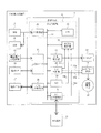
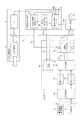
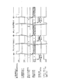
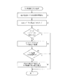
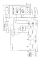
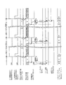
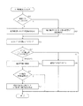
本発明の第1の実施の形態における画像形成装置の構成を示すブロック図である。1 is a block diagram illustrating a configuration of an image forming apparatus according to a first embodiment of the present invention. 本発明の第1の実施の形態における制御ユニットの要部の構成を示すブロック図である。It is a block diagram which shows the structure of the principal part of the control unit in the 1st Embodiment of this invention. 本発明の第1の実施の形態におけるモータ制御割込み処理に対する時間監視制御を示すタイムチャートである。It is a time chart which shows the time monitoring control with respect to the motor control interruption process in the 1st Embodiment of this invention. 本発明の第1の実施の形態におけるモータ制御割込み処理の動作を示すフローチャートである。It is a flowchart which shows the operation | movement of the motor control interruption process in the 1st Embodiment of this invention. 本発明の第2の実施の形態における制御ユニットの要部の構成を示すブロック図である。It is a block diagram which shows the structure of the principal part of the control unit in the 2nd Embodiment of this invention. 本発明の第2の実施の形態におけるモータ制御割込み処理に対する時間監視制御を示すタイムチャートである。It is a time chart which shows the time monitoring control with respect to the motor control interruption process in the 2nd Embodiment of this invention. 本発明の第2の実施の形態におけるモータ制御割込み処理の動作を示すフローチャートである。It is a flowchart which shows the operation | movement of the motor control interruption process in the 2nd Embodiment of this invention.

以下、本発明の実施の形態について図面を参照しながら詳細に説明する。   Hereinafter, embodiments of the present invention will be described in detail with reference to the drawings.

図1は本発明の第1の実施の形態における画像形成装置の構成を示すブロック図である。   FIG. 1 is a block diagram showing the configuration of the image forming apparatus according to the first embodiment of the present invention.

図において、10は画像形成装置であり、例えば、プリンタ、ファクシミリ機、複写機、プリンタ、ファクシミリ機及び複写機の機能を併せ持つ複合機(MFP:Multi Function Printer)等であって、インクジェット方式、電子写真方式、熱転写方式等の各種の画像形成方式を利用して、印刷用紙等の媒体に画像を形成することが可能な装置であれば、いかなる種類の画像形成装置であってもよい。なお、本実施の形態においては、前記画像形成装置10が熱転写方式のプリンタである場合について説明する。   In the figure, reference numeral 10 denotes an image forming apparatus, for example, a multi-function printer (MFP) having the functions of a printer, a facsimile machine, a copier, a printer, a facsimile machine, and a copier. Any type of image forming apparatus may be used as long as it can form an image on a medium such as printing paper by using various image forming systems such as a photographic system and a thermal transfer system. In the present embodiment, the case where the image forming apparatus 10 is a thermal transfer printer will be described.

そして、前記画像形成装置10は、図示されないネットワーク、USB(Universal Serial Bus)回線等の通信回線を介して、上位装置としてのホスト装置11と通信可能に接続されている。該ホスト装置11は、印刷データを含む印刷コマンドを作成して画像形成装置10に送信することができる装置であれば、いかなる種類の装置であってもよく、例えば、サーバ、PDA(Personal Digital Assistant)、電子手帳、ゲーム機、携帯電話機等であってもよいが、ここでは、例えば、CPU、MPU等の演算手段、磁気ディスク、半導体メモリ等の記憶手段、キーボード、マウス、タッチパネル等の入力手段、CRT、液晶ディスプレイ等の表示手段、通信インターフェイス等を備えるパーソナルコンピュータであるものとして説明する。   The image forming apparatus 10 is communicably connected to a host apparatus 11 serving as a host device via a communication line such as a network (not shown) or a USB (Universal Serial Bus) line. The host device 11 may be any type of device as long as it can create a print command including print data and transmit the print command to the image forming apparatus 10, for example, a server, a PDA (Personal Digital Assistant). ), Electronic notebook, game machine, mobile phone, etc., but here, for example, arithmetic means such as CPU and MPU, storage means such as magnetic disk and semiconductor memory, input means such as keyboard, mouse and touch panel A personal computer having a display means such as a CRT or a liquid crystal display, a communication interface, and the like will be described.

また、前記画像形成装置10は、該画像形成装置10の各部の動作を制御する制御装置としての制御ユニット12、記憶手段としてのROM13、記憶手段としてのRAM14、電源電圧分圧部としての電源電圧分圧回路15、温度検出手段としての温度センサ16、ユーザインターフェイスとしての操作パネル17、画像形成部である熱転写ヘッドとしてのサーマルヘッド18、モータ駆動部としてのモータドライバ回路19及びステッピングモータとしての媒体搬送モータ20を有する。   The image forming apparatus 10 includes a control unit 12 as a control device that controls the operation of each unit of the image forming apparatus 10, a ROM 13 as a storage unit, a RAM 14 as a storage unit, and a power supply voltage as a power supply voltage dividing unit. A voltage dividing circuit 15, a temperature sensor 16 as temperature detecting means, an operation panel 17 as a user interface, a thermal head 18 as a thermal transfer head as an image forming unit, a motor driver circuit 19 as a motor driving unit, and a medium as a stepping motor A conveyance motor 20 is included.

ここで、前記ROM13は、画像形成装置10を制御するプログラムとしてのプリンタ制御プログラムを格納する。また、前記RAM14は、前記プリンタ制御プログラムや画像形成装置10の制御に必要な各種データを格納する。さらに、前記電源電圧分圧回路15は、画像形成装置10の電源の電圧が規定している範囲を超えることがないか否かを確認する。さらに、前記温度センサ16は、発熱によって変化する媒体搬送モータ20の温度を検出し、該温度をアナログ信号に変換して出力する。   Here, the ROM 13 stores a printer control program as a program for controlling the image forming apparatus 10. The RAM 14 stores various data necessary for controlling the printer control program and the image forming apparatus 10. Further, the power supply voltage dividing circuit 15 confirms whether or not the voltage of the power supply of the image forming apparatus 10 exceeds the specified range. Further, the temperature sensor 16 detects the temperature of the medium transport motor 20 that changes due to heat generation, converts the temperature into an analog signal, and outputs the analog signal.

さらに、前記操作パネル17は、画像形成装置10のユーザが操作を行うためのスイッチ、画像形成装置10の状態を確認するための表示パネル等を備える。さらに、前記サーマルヘッド18は、熱転写印刷を行うことによって媒体に画像を形成する。さらに、前記モータドライバ回路19は、前記媒体搬送モータ20を駆動する。さらに、該媒体搬送モータ20は、媒体を搬送するローラ、ベルト等を駆動するための駆動源である。   Further, the operation panel 17 includes a switch for a user of the image forming apparatus 10 to perform an operation, a display panel for confirming the state of the image forming apparatus 10 and the like. Further, the thermal head 18 forms an image on a medium by performing thermal transfer printing. Further, the motor driver circuit 19 drives the medium transport motor 20. Further, the medium transport motor 20 is a drive source for driving a roller, a belt, or the like that transports the medium.

また、前記制御ユニット12は、メモリ制御部22とCPU23とを含む制御部としての中央制御部21、A/Dコンバータ24、パネルI/F制御部25、割込み制御部26、印刷制御部27、モータ制御部28、タイマ29及びホストI/F制御部30を備える。なお、前記メモリ制御部22、CPU23、A/Dコンバータ24、パネルI/F制御部25、割込み制御部26、印刷制御部27、モータ制御部28、タイマ29及びホストI/F制御部30は、通信回線としての内部バス31を介して、相互に通信可能に接続されている。   The control unit 12 includes a central control unit 21 as a control unit including a memory control unit 22 and a CPU 23, an A / D converter 24, a panel I / F control unit 25, an interrupt control unit 26, a print control unit 27, A motor control unit 28, a timer 29, and a host I / F control unit 30 are provided. The memory control unit 22, CPU 23, A / D converter 24, panel I / F control unit 25, interrupt control unit 26, print control unit 27, motor control unit 28, timer 29, and host I / F control unit 30 are Are connected to each other via an internal bus 31 as a communication line.

ここで、前記中央制御部21は、ステッピングモータとしての媒体搬送モータ20の割込み制御処理を実行する。そして、前記メモリ制御部22は、前記ROM13及びRAM14と通信可能に接続され、前記ROM13及びRAM14のリード(読取り)及びライト(書込み)を行う。また、前記CPU23は、演算手段であって、前記メモリ制御部22を介してリードしたプリンタ制御プログラムを実行する。さらに、前記A/Dコンバータ24は、電源電圧分圧回路15及び温度センサ16が出力するアナログ信号をデジタル信号に変換する。さらに、前記パネルI/F制御部25は、前記操作パネル17にアクセスし、該操作パネル17のスイッチのリードや、表示パネルの表示指示を行う。   Here, the central control unit 21 executes an interrupt control process of the medium transport motor 20 as a stepping motor. The memory control unit 22 is communicably connected to the ROM 13 and the RAM 14, and reads (writes) and writes (writes) the ROM 13 and the RAM 14. The CPU 23 is a calculation unit, and executes a printer control program read via the memory control unit 22. Further, the A / D converter 24 converts an analog signal output from the power supply voltage dividing circuit 15 and the temperature sensor 16 into a digital signal. Further, the panel I / F control unit 25 accesses the operation panel 17 to read a switch of the operation panel 17 and to display the display panel.

そして、前記ホストI/F制御部30は、ホスト装置11に接続され、印刷データの受信や制御データの送受信を行う。また、前記タイマ29は、計時手段であって、操作パネル17の制御等、周期的に処理を発生させるためのトリガとして機能する。さらに、前記モータ制御部28は、媒体搬送モータ20を駆動するための信号制御を行う。具体的には、ステッピングモータである媒体搬送モータ20へ供給される電流を切替えるための相切替信号37a、及び、各相の電流値に相当するPWM(Pulse Width Modulation:パルス幅変調)制御のオンデューティ時間を決定するための電流制御信号37bを、媒体搬送モータ20を駆動するモータドライバ回路19に出力する。   The host I / F control unit 30 is connected to the host device 11 and receives print data and transmits / receives control data. The timer 29 is a time measuring means and functions as a trigger for periodically generating processing such as control of the operation panel 17. Further, the motor control unit 28 performs signal control for driving the medium transport motor 20. Specifically, the phase switching signal 37a for switching the current supplied to the medium transport motor 20 that is a stepping motor, and the PWM (Pulse Width Modulation) control corresponding to the current value of each phase are turned on. A current control signal 37 b for determining the duty time is output to the motor driver circuit 19 that drives the medium transport motor 20.

また、前記印刷制御部27は、サーマルヘッド18を駆動するための信号制御を行う。さらに、前記割込み制御部26は、モータ制御部28、タイマ29及びホストI/F制御部30から出力される第1〜第3割込み要求信号32a〜32cを監視し、割込み要求が発生したことを検出するとCPU23に通知する。   The print control unit 27 performs signal control for driving the thermal head 18. Further, the interrupt control unit 26 monitors the first to third interrupt request signals 32a to 32c output from the motor control unit 28, the timer 29, and the host I / F control unit 30 to confirm that an interrupt request has occurred. When detected, the CPU 23 is notified.

なお、前記モータ制御部28から割込み制御部26へ出力される割込み要求信号としての第1割込み要求信号32aは、ステッピングモータである媒体搬送モータ20の相切替タイミングをCPU23に通知するために使用される。また、前記タイマ29から割込み制御部26へ出力される割込み要求信号としての第2割込み要求信号32bは、操作パネル17の定期的な監視を行うために、一定の間隔でCPU23に通知するために使用される。さらに、前記ホストI/F制御部30から割込み制御部26へ出力される割込み要求信号としての第3割込み要求信号32cは、ホスト装置11からの印刷データの処理を速やかに実行するために、ホスト装置11からの印刷データの受信が検出されたときにCPU23に通知するために使用される。   The first interrupt request signal 32a as an interrupt request signal output from the motor control unit 28 to the interrupt control unit 26 is used to notify the CPU 23 of the phase switching timing of the medium transport motor 20 which is a stepping motor. The The second interrupt request signal 32b as an interrupt request signal output from the timer 29 to the interrupt control unit 26 is used to notify the CPU 23 at regular intervals in order to periodically monitor the operation panel 17. used. Further, the third interrupt request signal 32c as an interrupt request signal output from the host I / F control unit 30 to the interrupt control unit 26 is used to promptly execute processing of print data from the host device 11. Used to notify the CPU 23 when reception of print data from the apparatus 11 is detected.

次に、前記制御ユニット12の構成について詳細に説明する。   Next, the configuration of the control unit 12 will be described in detail.

図2は本発明の第1の実施の形態における制御ユニットの要部の構成を示すブロック図である。   FIG. 2 is a block diagram showing a configuration of a main part of the control unit according to the first embodiment of the present invention.

本実施の形態における割込み処理のための制御は、主として、中央制御部21、A/Dコンバータ24、割込み制御部26及びモータ制御部28によって実行される。そして、前記割込み制御部26は、図に示されるように、割込み要求レジスタ33、割込み時間監視カウンタ34及び割込み監視時間設定レジスタ35を備える。   Control for interrupt processing in the present embodiment is mainly executed by the central control unit 21, the A / D converter 24, the interrupt control unit 26, and the motor control unit 28. The interrupt control unit 26 includes an interrupt request register 33, an interrupt time monitoring counter 34, and an interrupt monitoring time setting register 35, as shown in the figure.

前記割込み要求レジスタ33は、割込み要求を発生する特定の割込みソースとしてのモータ制御部28からの第1割込み要求信号32a、並びに、割込み要求を発生するその他の割込みソースとしてのタイマ29及びホストI/F制御部30からの第2割込み要求信号32b及び第3割込み要求信号32cを受信し、CPU23に割込み要求が発生したことを通知する。また、前記割込み要求レジスタ33は、設定に応じて、割込み時間監視カウンタ34にも、割込み要求が発生したことを通知する。   The interrupt request register 33 includes a first interrupt request signal 32a from the motor control unit 28 as a specific interrupt source that generates an interrupt request, a timer 29 and a host I / O as other interrupt sources that generate an interrupt request. The second interrupt request signal 32b and the third interrupt request signal 32c from the F control unit 30 are received, and the CPU 23 is notified that an interrupt request has occurred. The interrupt request register 33 also notifies the interrupt time monitoring counter 34 that an interrupt request has occurred according to the setting.

そして、前記割込み時間監視カウンタ34は、割込みソースのうちの特定の割込みソースの割込み要求が発生してからの時間が制限時間を経過するとカウントアップ信号を出力する。具体的には、割込み要求レジスタ33から特定の割込みソースの割込み要求が発生した旨の通知を受けると、カウントを開始する。これは、割込み要求が発生した時点からの時間をカウントするためである。   The interrupt time monitoring counter 34 outputs a count-up signal when a time limit has elapsed since the occurrence of an interrupt request for a specific interrupt source among the interrupt sources. Specifically, the count is started upon receiving a notification from the interrupt request register 33 that an interrupt request of a specific interrupt source has occurred. This is because the time from when the interrupt request is generated is counted.

本実施の形態の場合、前記割込み要求レジスタ33は、第1割込み要求信号32aがハイレベルになったことを検出すると、割込み時間監視カウンタ34へ割込み要求が発生したことを通知する。しかし、第2割込み要求信号32b又は第3割込み要求信号32cがハイレベルになったことを検出しても、割込み時間監視カウンタ34へは割込み要求が発生したことを通知しない。   In the present embodiment, when the interrupt request register 33 detects that the first interrupt request signal 32a has become high level, it notifies the interrupt time monitoring counter 34 that an interrupt request has occurred. However, even if it is detected that the second interrupt request signal 32b or the third interrupt request signal 32c has become high level, the interrupt time monitoring counter 34 is not notified that an interrupt request has occurred.

一般的に、ステッピングモータの制御においては、割込み発生タイミング毎に制御を確実に実行しなければならない。そのため、前記割込み時間監視カウンタ34は、モータ制御部28からの割込み要求だけを監視する必要がある。しかし、タイマ29やホストI/F制御部30からの割込み要求については、割込み処理の開始が遅れても致命的な障害が発生しないため、前記割込み時間監視カウンタ34が監視を行う必要はない。   In general, in the control of a stepping motor, the control must be surely executed at every interrupt generation timing. Therefore, the interrupt time monitoring counter 34 needs to monitor only the interrupt request from the motor control unit 28. However, regarding the interrupt request from the timer 29 or the host I / F control unit 30, since the fatal failure does not occur even if the start of the interrupt processing is delayed, the interrupt time monitoring counter 34 does not need to be monitored.

前記割込み監視時間設定レジスタ35は、割込み時間監視カウンタ34がカウントする時間を格納しておくレジスタである。前記カウントする時間は、前記制限時間であって、あらかじめ中央制御部21によって、割込み時間監視カウンタ34に設定されている。そして、前記カウントする時間が経過したタイミングにおいて、前記割込み時間監視カウンタ34は、カウントアップ信号としての時間監視カウントアップ信号36を出力する。具体的には、時間監視カウントアップ信号36をハイレベルにして、A/Dコンバータ24へ出力する。   The interrupt monitoring time setting register 35 is a register for storing the time counted by the interrupt time monitoring counter 34. The counting time is the time limit, and is set in the interrupt time monitoring counter 34 by the central control unit 21 in advance. Then, at the timing when the counting time has elapsed, the interrupt time monitoring counter 34 outputs a time monitoring count-up signal 36 as a count-up signal. Specifically, the time monitoring count up signal 36 is set to the high level and output to the A / D converter 24.

該A/Dコンバータ24は、レジスタとしての第1レジスタ41及び第2レジスタ42、セレクタ部としてのセレクタ回路43、情報付加部としての情報付加回路44、デコード部としてのデコード回路45並びにA/D変換部46を備える。   The A / D converter 24 includes a first register 41 and a second register 42 as registers, a selector circuit 43 as a selector unit, an information adding circuit 44 as an information adding unit, a decoding circuit 45 as a decoding unit, and an A / D. A conversion unit 46 is provided.

そして、前記第1レジスタ41は、第1チャンネルCH1を介して電源電圧分圧回路15から入力されたアナログ信号の電圧値をA/D変換部46によってデジタル値に変換した値を格納する。また、前記第2レジスタ42は、ステッピングモータの状態を示すモータ状態情報を格納して出力するモータ状態情報レジスタとして機能する。具体的には、第2チャンネルCH2を介して温度センサ16から入力されたアナログ信号の電圧値をA/D変換部46によってデジタル値に変換した値を格納する。   The first register 41 stores a value obtained by converting the voltage value of the analog signal input from the power supply voltage divider circuit 15 through the first channel CH1 into a digital value by the A / D converter 46. The second register 42 functions as a motor status information register that stores and outputs motor status information indicating the status of the stepping motor. Specifically, a value obtained by converting the voltage value of the analog signal input from the temperature sensor 16 through the second channel CH2 into a digital value by the A / D converter 46 is stored.

さらに、前記デコード回路45は、中央制御部21からレジスタのリード要求が発生した場合、中央制御部21から出力されたアドレスデータ49で要求されたレジスタアドレスの値に基づいて、第1レジスタ41及び第2レジスタ42から該当するレジスタを選択する。具体的には、前記デコード回路45は、中央制御部21から出力されたアドレスデータ49に該当するレジスタが第1レジスタ41であるか、第2レジスタ42であるかを決定し、セレクタ回路43に対してレジスタセレクト信号51を出力する。   Further, when a read request of the register is generated from the central control unit 21, the decode circuit 45 determines the first register 41 and the first register 41 based on the value of the register address requested by the address data 49 output from the central control unit 21. A corresponding register is selected from the second register 42. Specifically, the decode circuit 45 determines whether the register corresponding to the address data 49 output from the central control unit 21 is the first register 41 or the second register 42, and sends it to the selector circuit 43. In response to this, a register select signal 51 is output.

そして、前記セレクタ回路43は、デコード回路45が選択したレジスタに格納されている値を、情報付加回路44に出力する。具体的には、前記セレクタ回路43は、入力されている複数のレジスタのデータから、レジスタセレクト信号51によって指定されたレジスタのデータを選択し、レジスタデータ47として、情報付加回路44に出力する。   Then, the selector circuit 43 outputs the value stored in the register selected by the decoding circuit 45 to the information adding circuit 44. Specifically, the selector circuit 43 selects the register data designated by the register select signal 51 from the input data of the plurality of registers, and outputs it as the register data 47 to the information adding circuit 44.

該情報付加回路44は、時間監視カウントアップ信号36が出力されると、第2レジスタ42が出力したモータ状態情報に付加情報を付加する。具体的には、割込み時間監視カウンタ34から入力された時間監視カウントアップ信号36の値を、内部バス31に出力するレジスタリードデータ48のMSB(Most Significant Bit:最上位のビット)に付加情報として付加する。そして、レジスタリードデータ48のMSB以外の部分には、セレクタ回路43から入力されるレジスタデータ47をセットする。   When the time monitoring count up signal 36 is output, the information adding circuit 44 adds additional information to the motor state information output from the second register 42. Specifically, the value of the time monitoring count-up signal 36 input from the interrupt time monitoring counter 34 is added as additional information to the MSB (Most Significant Bit: most significant bit) of the register read data 48 output to the internal bus 31. Append. Then, register data 47 input from the selector circuit 43 is set in a portion other than the MSB of the register read data 48.

本実施の形態においては、時間監視カウントアップ信号36の値をレジスタリードデータ48のMSBに付加する場合について説明したが、時間監視カウントアップ信号36の値を付加していることを認識することができるのであれば、時間監視カウントアップ信号36の値を付加する部分は、必ずしもMSBに限定されるものではなく、例えば、LSB(Least Significant Bit:最下位のビット)であってもよく、いかなる部分であってもよい。   In the present embodiment, the case where the value of the time monitoring count up signal 36 is added to the MSB of the register read data 48 has been described. However, it can be recognized that the value of the time monitoring count up signal 36 is added. If possible, the part to which the value of the time monitoring count-up signal 36 is added is not necessarily limited to the MSB, and may be, for example, an LSB (Least Significant Bit), and any part. It may be.

次に、前記構成の画像形成装置10の動作について説明する。ここでは、媒体搬送モータ20を制御するための割込み制御処理であるモータ制御割込み処理の動作について説明する。まず、モータ制御割込み処理に対する時間監視制御について説明する。   Next, the operation of the image forming apparatus 10 having the above configuration will be described. Here, the operation of a motor control interrupt process, which is an interrupt control process for controlling the medium transport motor 20, will be described. First, time monitoring control for motor control interrupt processing will be described.

図3は本発明の第1の実施の形態におけるモータ制御割込み処理に対する時間監視制御を示すタイムチャートである。   FIG. 3 is a time chart showing the time monitoring control for the motor control interrupt processing in the first embodiment of the present invention.

ステッピングモータである媒体搬送モータ20が回転中であれば、相切替のタイミング毎にモータ制御割込み処理が発生する。   If the medium transport motor 20 that is a stepping motor is rotating, a motor control interrupt process is generated at each phase switching timing.

本実施の形態において、割込み要求レジスタ33は、特定の割込みソースとしてのモータ制御部28からの割込み要求信号である第1割込み要求信号32aがハイレベルになったことを検出すると、割込み時間監視カウンタ34へ割込み要求が発生したことを通知する。しかし、その他の割込みソースとしてのタイマ29及びホストI/F制御部30からの割込み要求信号である第2割込み要求信号32b及び第3割込み要求信号32cがハイレベルになったことを検出しても、割込み時間監視カウンタ34へは割込み要求が発生したことを通知しない。   In the present embodiment, when the interrupt request register 33 detects that the first interrupt request signal 32a, which is an interrupt request signal from the motor control unit 28 as a specific interrupt source, has become high level, the interrupt time monitoring counter 34 is notified that an interrupt request has occurred. However, even if it is detected that the second interrupt request signal 32b and the third interrupt request signal 32c, which are interrupt request signals from the timer 29 and the host I / F control unit 30 as other interrupt sources, become high level. The interrupt time monitoring counter 34 is not notified that an interrupt request has occurred.

そして、ステッピングモータである媒体搬送モータ20が回転中であれば、モータ制御部28は、図に示されるように、ステッピングモータである媒体搬送モータ20へ供給される電流を切替えるための相切替信号37aを出力するとともに、第1割込み要求信号32aを出力する。該第1割込み要求信号32aは、相切替信号37aがハイレベルになるタイミング、すなわち、相切替えタイミング毎にアサートされてハイレベルになる。そして、第1割込み要求信号32aがハイレベルになると、割込み要求レジスタ33は、割込み時間監視カウンタ34へ割込み要求が発生したことを通知する。すると、割込み時間監視カウンタ34は、割込み監視時間設定レジスタ35に設定されている値、すなわち、制限時間をロードしてカウント動作を開始する。なお、割込み監視時間設定レジスタ35に設定される値は、相切替えタイミングの間隔、すなわち、割込み発生間隔よりも短い時間にする。   If the medium transport motor 20 that is the stepping motor is rotating, the motor control unit 28 switches the phase switching signal for switching the current supplied to the medium transport motor 20 that is the stepping motor, as shown in the figure. 37a is output and the first interrupt request signal 32a is output. The first interrupt request signal 32a is asserted and becomes high level at the timing when the phase switching signal 37a becomes high level, that is, at each phase switching timing. When the first interrupt request signal 32a becomes high level, the interrupt request register 33 notifies the interrupt time monitoring counter 34 that an interrupt request has occurred. Then, the interrupt time monitoring counter 34 loads the value set in the interrupt monitoring time setting register 35, that is, the time limit, and starts the counting operation. The value set in the interrupt monitoring time setting register 35 is set to a time shorter than the interval of the phase switching timing, that is, the interrupt generation interval.

そして、割込み時間監視カウンタ34のカウント値が0になると、カウントアップとなり、割込み時間監視カウンタ34は、時間監視カウントアップ信号36をハイレベルにして、A/Dコンバータ24へ出力する。すると、情報付加回路44は、時間監視カウントアップ信号36の値をレジスタリードデータ48のMSBに付加する。これにより、A/Dコンバータ24から出されるレジスタリードデータ48のMSBの値が1になる。   When the count value of the interrupt time monitoring counter 34 becomes 0, the count is incremented, and the interrupt time monitoring counter 34 sets the time monitoring count up signal 36 to the high level and outputs it to the A / D converter 24. Then, the information addition circuit 44 adds the value of the time monitoring count up signal 36 to the MSB of the register read data 48. As a result, the MSB value of the register read data 48 output from the A / D converter 24 becomes 1.

次に、中央制御部21が実行するモータ制御割込み処理について説明する。   Next, motor control interrupt processing executed by the central control unit 21 will be described.

図4は本発明の第1の実施の形態におけるモータ制御割込み処理の動作を示すフローチャートである。   FIG. 4 is a flowchart showing the operation of the motor control interrupt process in the first embodiment of the present invention.

特定の割込みソースとしてのモータ制御部28からの割込み要求信号である第1割込み要求信号32aがハイレベルになって割込み要求が発生すると、中央制御部21は、モータ制御割込み処理を開始し、媒体搬送モータ20の相切替制御を継続するために、モータ制御部28に次の相切替時間を設定する。なお、前回のモータ制御割込み処理において、媒体搬送モータ20の回転速度の補正値が算出された場合には、該補正値を適用する。   When the first interrupt request signal 32a, which is an interrupt request signal from the motor control unit 28 as a specific interrupt source, becomes high level and an interrupt request is generated, the central control unit 21 starts motor control interrupt processing, In order to continue the phase switching control of the transport motor 20, the next phase switching time is set in the motor control unit 28. If a correction value for the rotation speed of the medium transport motor 20 is calculated in the previous motor control interruption process, the correction value is applied.

続いて、中央制御部21は、媒体搬送モータ20の温度を把握するために、A/Dコンバータ24の第2レジスタ42のリードを行う。具体的には、時間監視カウントアップ信号36の値がMSBに付加されたレジスタリードデータ48のリードを行う。   Subsequently, the central control unit 21 reads the second register 42 of the A / D converter 24 in order to grasp the temperature of the medium transport motor 20. Specifically, the register read data 48 in which the value of the time monitoring count up signal 36 is added to the MSB is read.

続いて、中央制御部21は、レジスタリードデータ48のMSB=1であるか否かを判断する。つまり、リードを行ったレジスタリードデータ48のMSBの値を確認し、MSB=1であるか、MSB=0であるかを判断する。   Subsequently, the central control unit 21 determines whether or not the MSB = 1 of the register read data 48. That is, the MSB value of the read register read data 48 is confirmed, and it is determined whether MSB = 1 or MSB = 0.

そして、MSB=1である場合、割込み要求発生からの時間が制限時間を経過している、すなわち、オーバーしていると判断することができるので、中央制御部21は、割込み発生間隔を守るため、以降の動作を実行することなく、直ちにモータ制御割込み処理を終了する。   When the MSB = 1, it can be determined that the time from the occurrence of the interrupt request has passed the time limit, that is, exceeded, so the central control unit 21 keeps the interrupt generation interval. The motor control interrupt process is immediately terminated without executing the subsequent operations.

なお、制限時間をオーバーしている状態が発生した要因としては、例えば、割込み要求発生時点で、モータ制御割込み処理よりも高いプライオリティが与えられた他の処理が実行されていることが考えられる。中央制御部21が他の処理を実行していると、モータ制御割込み処理の開始が待たされる。そして、長い時間待たされた後に処理を開始しても、モータ制御割込み処理のすべての処理ステップを実行完了する前に、次回のモータ制御割込みが発生してしまう。そのため、割込み要求発生からの時間が制限時間をオーバーしていた場合には、未実行の処理ステップを実行せずに、直ちにモータ制御割込み処理を終了する必要がある。   As a cause of the occurrence of the state in which the time limit is exceeded, for example, it is conceivable that another process having a higher priority than the motor control interrupt process is executed at the time when the interrupt request is generated. If the central control unit 21 is executing another process, the start of the motor control interrupt process is awaited. Even if the process is started after waiting for a long time, the next motor control interrupt occurs before the completion of the execution of all the process steps of the motor control interrupt process. For this reason, if the time from the generation of the interrupt request exceeds the time limit, it is necessary to immediately terminate the motor control interrupt process without executing the unexecuted process step.

ここで、前記未実行の処理ステップは、媒体搬送モータ20の温度情報に関する処理である。該温度情報に関する処理とは、媒体搬送モータ20の温度の情報を認識して、モータ制御部28にフィードバックを行う処理のことである。しかし、ステッピングモータである媒体搬送モータ20の相切替タイミングの間隔、すなわち、割込み発生間隔は、数百〔μs〕程度の短時間であり、このような短時間では媒体搬送モータ20の温度は急激には変化しない。したがって、前記温度情報に関する処理を今回のモータ制御割込み処理内に実行することができなくても、次回のモータ制御割込み処理で実行することができれば、媒体搬送モータ20の制御において重大な不具合が発生することはない。   Here, the unexecuted processing step is processing related to temperature information of the medium transport motor 20. The process related to the temperature information is a process of recognizing the temperature information of the medium transport motor 20 and performing feedback to the motor control unit 28. However, the interval of the phase switching timing of the medium transport motor 20 which is a stepping motor, that is, the interrupt generation interval is a short time of about several hundreds [μs], and the temperature of the medium transport motor 20 rapidly increases in such a short time. Does not change. Therefore, even if the process related to the temperature information cannot be executed in the current motor control interrupt process, if it can be executed in the next motor control interrupt process, a serious problem occurs in the control of the medium transport motor 20. Never do.

また、レジスタリードデータ48のMSB=1であるか否かを判断してMSB=0である場合、中央制御部21は、A/Dコンバータ24の値をモータ温度に換算する。具体的には、レジスタリードデータ48のリードを行って得られたデータに含まれる温度センサ16から入力された値を媒体搬送モータ20の温度に換算する。   If the MSB of the register read data 48 is determined to be 1 MSB = 0, the central control unit 21 converts the value of the A / D converter 24 into the motor temperature. Specifically, the value input from the temperature sensor 16 included in the data obtained by reading the register read data 48 is converted into the temperature of the medium transport motor 20.

続いて、中央制御部21は、モータ温度が規定温度より低いか否かを判断する。具体的には、媒体搬送モータ20の温度があらかじめ設定された規定温度よりも低いか否かを判断する。   Subsequently, the central control unit 21 determines whether or not the motor temperature is lower than the specified temperature. Specifically, it is determined whether or not the temperature of the medium transport motor 20 is lower than a preset specified temperature.

そして、モータ温度が規定温度より低くない、すなわち、規定温度以上である場合、中央制御部21は、現状の温度に対応したモータ制御の補正値を算出し、モータ制御割込み処理を終了する。具体的には、媒体搬送モータ20の温度を下げるために、媒体搬送モータ20の回転速度を低下させるための補正値を算出するとともに、媒体搬送モータ20を駆動するモータドライバ回路19へ出力される電流制御信号37bの補正値を算出して、モータ制御割込み処理を終了する。前記補正値は、次回のモータ制御割込み処理で適用される。   When the motor temperature is not lower than the specified temperature, that is, when the motor temperature is equal to or higher than the specified temperature, the central control unit 21 calculates a motor control correction value corresponding to the current temperature, and ends the motor control interrupt process. Specifically, in order to lower the temperature of the medium transport motor 20, a correction value for decreasing the rotation speed of the medium transport motor 20 is calculated and output to the motor driver circuit 19 that drives the medium transport motor 20. The correction value of the current control signal 37b is calculated, and the motor control interrupt process is terminated. The correction value is applied in the next motor control interruption process.

また、モータ温度が規定温度より低いか否かを判断して低い場合、すなわち、媒体搬送モータ20の温度があらかじめ設定された規定温度よりも低い場合、媒体搬送モータ20の温度を下げる必要がないので、中央制御部21は、直ちにモータ制御割込み処理を終了する。   If it is determined whether the motor temperature is lower than the specified temperature, that is, if the temperature of the medium transport motor 20 is lower than a predetermined temperature, it is not necessary to lower the temperature of the medium transport motor 20. Therefore, the central control unit 21 immediately ends the motor control interrupt process.

次に、フローチャートについて説明する。
ステップS1 媒体搬送モータ20の相切替時間を設定する。
ステップS2 A/Dコンバータ24の第2レジスタ42のリードを行う。
ステップS3 レジスタリードデータ48のMSB=1か否かを判断する。レジスタリードデータ48のMSB=1である場合は処理を終了し、レジスタリードデータ48のMSB=1でない場合はステップS4に進む。
ステップS4 A/Dコンバータ24の値を媒体搬送モータ20の温度に換算する。
ステップS5 媒体搬送モータ20の温度が規定温度よりも低いか否かを判断する。媒体搬送モータ20の温度が規定温度よりも低い場合は処理を終了し、媒体搬送モータ20の温度が規定温度より低くない場合はステップS6に進む。
ステップS6 現状の温度に対応したモータ制御の補正値を算出し、処理を終了する。
Next, a flowchart will be described.
Step S1: The phase switching time of the medium transport motor 20 is set.
Step S2: Read the second register 42 of the A / D converter 24.
Step S3: It is determined whether or not the MSB of the register read data 48 = 1. If the MSB of the register read data 48 is 1, the process ends. If the MSB of the register read data 48 is not 1, the process proceeds to step S4.
Step S4: The value of the A / D converter 24 is converted into the temperature of the medium transport motor 20.
Step S5: It is determined whether or not the temperature of the medium transport motor 20 is lower than a specified temperature. If the temperature of the medium transport motor 20 is lower than the specified temperature, the process ends. If the temperature of the medium transport motor 20 is not lower than the specified temperature, the process proceeds to step S6.
Step S6: A motor control correction value corresponding to the current temperature is calculated, and the process ends.

このように、本実施の形態において、中央制御部21は、特定の割込みソースとしてのモータ制御部28の割込み要求が発生するとモータ割込み制御処理を開始し、モータ状態情報としての第2レジスタ42のレジスタリードデータ48の読取りを行い、該レジスタリードデータ48に付加情報が付加されている場合にはモータ割込み制御処理を途中で終了する。なお、レジスタリードデータ48に付加情報が付加されていない場合には、モータ状態情報としてのモータ温度に基づくフィードバック処理を実行した後に、モータ割込み制御処理を終了する。   As described above, in the present embodiment, the central control unit 21 starts the motor interrupt control process when an interrupt request from the motor control unit 28 as a specific interrupt source is generated, and the second register 42 as the motor status information. The register read data 48 is read, and if additional information is added to the register read data 48, the motor interrupt control process is terminated halfway. If no additional information is added to the register read data 48, the motor interrupt control process is terminated after executing a feedback process based on the motor temperature as the motor status information.

ここで、割込み要求レジスタ33は、特定の割込みソースとしてのモータ制御部28からの割込み要求信号がハイレベルになったことを検出すると、割込み時間監視カウンタ34へ割込み要求が発生したことを通知するが、その他の割込みソースからの割込み要求信号がハイレベルになったことを検出しても割込み時間監視カウンタ34へは割込み要求が発生したことを通知しないようになっている。そして、割込み時間監視カウンタ34は、割込み要求が発生したことが通知されると、レジスタリードデータ48の特定の部分に割込み要求が発生した旨を示す情報を付加する。   Here, when the interrupt request register 33 detects that the interrupt request signal from the motor control unit 28 as a specific interrupt source has become high level, the interrupt request register 33 notifies the interrupt time monitoring counter 34 that an interrupt request has occurred. However, even if it is detected that the interrupt request signal from another interrupt source has become high level, the interrupt time monitoring counter 34 is not notified that the interrupt request has occurred. Then, when notified that an interrupt request has occurred, the interrupt time monitoring counter 34 adds information indicating that the interrupt request has occurred to a specific portion of the register read data 48.

これにより、レジスタリードデータ48のリードを行う通常のレジスタリードサイクルによって、割込み要求が発生した旨を示す情報を読取ることができ、周期的に発生するステッピングモータである媒体搬送モータ20の相切替タイミングの間隔に影響を与えないようにモータ制御割込み処理を途中で終了する等、処理内容を変更することができる。   Thus, information indicating that an interrupt request has been generated can be read by a normal register read cycle in which the register read data 48 is read, and the phase switching timing of the medium transport motor 20 that is a stepping motor that is generated periodically. The processing content can be changed, for example, the motor control interrupt processing is terminated in the middle so as not to affect the interval.

したがって、ステッピングモータである媒体搬送モータ20の相切替タイミングに影響を与えることなく、媒体搬送モータ20を安定して制御することができる。   Therefore, the medium transport motor 20 can be stably controlled without affecting the phase switching timing of the medium transport motor 20 that is a stepping motor.

換言すると、割込み処理時間が規定された制限時間を超えたことを割込み処理内で通常リードするレジスタリードデータ48の特定ビットに付加する情報付加回路44によって、読取りを行ったレジスタリードデータ48の値から割込み処理時間の状況を判断することができる機能を備える。このように、レジスタリードデータ48のリードサイクルによって割込み処理時間の経過状況を認識することができるので、制限時間が経過してしまった場合には、モータ制御割込み処理を途中で終了することができる。モータ制御割込み処理の実行時に制限時間の経過を認識することで、モータ制御割込み処理の継続可否を判断することができる。定期的に発生するモータ制御割込み処理において、処理の継続や終了を判断することによって、モータ制御割込み処理を、次回の割込み発生タイミングを超えずに終了することができる。   In other words, the value of the register read data 48 that has been read by the information adding circuit 44 that adds to the specific bit of the register read data 48 that is normally read in the interrupt processing that the interrupt processing time has exceeded the specified time limit. It has a function that can determine the status of interrupt processing time. As described above, since the progress of the interrupt processing time can be recognized by the read cycle of the register read data 48, when the time limit has elapsed, the motor control interrupt processing can be terminated halfway. . By recognizing the passage of the time limit when executing the motor control interrupt process, it is possible to determine whether or not the motor control interrupt process can be continued. By determining the continuation or termination of the process in the regularly generated motor control interrupt process, the motor control interrupt process can be terminated without exceeding the next interrupt generation timing.

次に、本発明の第2の実施の形態について説明する。なお、第1の実施の形態と同じ構成を有するものについては、同じ符号を付与することによって、その説明を省略する。また、前記第1の実施の形態と同じ動作及び同じ効果についても、その説明を省略する。   Next, a second embodiment of the present invention will be described. In addition, about what has the same structure as 1st Embodiment, the description is abbreviate | omitted by providing the same code | symbol. The description of the same operation and the same effect as those of the first embodiment is also omitted.

図5は本発明の第2の実施の形態における制御ユニットの要部の構成を示すブロック図である。   FIG. 5 is a block diagram showing the configuration of the main part of the control unit according to the second embodiment of the present invention.

本実施の形態において、A/Dコンバータ24は、第1レジスタ41、第2レジスタ42、セレクタ回路43、情報付加回路44、デコード回路45及びA/D変換部46に加えて、リード回数カウンタ52を備える。   In this embodiment, the A / D converter 24 includes a read number counter 52 in addition to the first register 41, the second register 42, the selector circuit 43, the information addition circuit 44, the decoding circuit 45, and the A / D conversion unit 46. Is provided.

該リード回数カウンタ52は、直近の過去において、特定の割込みソースの割込み要求が発生してからの時間が制限時間を経過した回数をカウントして経過回数を出力する経過回数カウンタとして機能する。具体的には、割込み時間監視カウンタ34が出力する時間監視カウントアップ信号36、及び、デコード回路45が出力するレジスタセレクト信号51を監視する。そして、該レジスタセレクト信号51に基づいて、レジスタとしての第1レジスタ41及び第2レジスタ42に対するアクセスが行われているか否かを認識することができる。また、前記時間監視カウントアップ信号36に基づいて、割込み要求発生からの時間が制限時間を経過しているか否かを認識することができる。   The read count counter 52 functions as an elapsed count counter that counts the number of times that the time limit has elapsed since the occurrence of an interrupt request of a specific interrupt source in the most recent past and outputs the elapsed count. Specifically, the time monitor count-up signal 36 output from the interrupt time monitor counter 34 and the register select signal 51 output from the decode circuit 45 are monitored. Based on the register select signal 51, it is possible to recognize whether the first register 41 and the second register 42 as registers are being accessed. Further, based on the time monitoring count-up signal 36, it can be recognized whether or not the time from the generation of the interrupt request has passed the time limit.

つまり、リード回数カウンタ52は、割込み要求発生からの時間が制限時間を経過したという条件の下で該当するレジスタに対するアクセスが行われたか否かを認識することができ、アクセスが行われた場合には、その回数をカウントする。そして、レジスタに対する連続アクセスを検出した場合、リード回数カウンタ52は、連続アクセス検出信号53を情報付加回路44に対して出力する。   In other words, the read number counter 52 can recognize whether or not the corresponding register has been accessed under the condition that the time from the occurrence of the interrupt request has exceeded the time limit. Counts the number of times. When a continuous access to the register is detected, the read number counter 52 outputs a continuous access detection signal 53 to the information adding circuit 44.

本実施の形態における情報付加回路44は、割込み時間監視カウンタ34から入力された時間監視カウントアップ信号36の値を、内部バス31に出力するレジスタリードデータ48のMSBに付加する機能に加えて、リード回数カウンタ52が出力した連続アクセス検出信号53の情報をMSBから下位1ビットに付加する機能を備える。したがって、レジスタリードデータ48の最上位2ビットを読取ることによって、モータ制御割込み処理におけるレジスタリードサイクルに関する情報を取得することができる。また、レジスタリードデータ48の最上位2ビット以外の部分には、セレクタ回路43から入力されるレジスタデータ47をセットする。   In addition to the function of adding the value of the time monitoring count up signal 36 input from the interrupt time monitoring counter 34 to the MSB of the register read data 48 output to the internal bus 31, the information adding circuit 44 in the present embodiment includes: It has a function of adding the information of the continuous access detection signal 53 output from the read counter 52 to the lower 1 bit from the MSB. Therefore, by reading the most significant 2 bits of the register read data 48, it is possible to obtain information related to the register read cycle in the motor control interrupt process. Further, register data 47 input from the selector circuit 43 is set in a portion other than the most significant 2 bits of the register read data 48.

例えば、第2レジスタ42のリードを行う場合、デコード回路45は、中央制御部21から出力されたアドレスデータ49で要求されたレジスタアドレスの値に基づいて該当するレジスタを決定し、セレクタ回路43に対してレジスタセレクト信号51を出力する。すると、該レジスタセレクト信号51が入力されたセレクタ回路43は、入力されている複数のレジスタのデータから、前記デコード回路45が決定したレジスタのデータを選択し、レジスタデータ47として情報付加回路44に対して出力する。そして、該情報付加回路44は、入力されたレジスタデータ47をレジスタリードデータ48の最上位2ビット以外の部分にそのままセットし、時間監視カウントアップ信号36及び連続アクセス検出信号53の値をレジスタリードデータ48の最上位2ビットにセットする。   For example, when reading the second register 42, the decode circuit 45 determines the corresponding register based on the value of the register address requested by the address data 49 output from the central control unit 21, and sends it to the selector circuit 43. In response to this, a register select signal 51 is output. Then, the selector circuit 43 to which the register select signal 51 is input selects the register data determined by the decode circuit 45 from the input data of the plurality of registers, and the register data 47 is sent to the information adding circuit 44. Output. Then, the information adding circuit 44 sets the input register data 47 as it is in the portion other than the most significant 2 bits of the register read data 48, and registers the values of the time monitoring count-up signal 36 and the continuous access detection signal 53 as register read. Set to the most significant 2 bits of data 48.

本実施の形態においては、時間監視カウントアップ信号36及び連続アクセス検出信号53の値をレジスタリードデータ48の最上位2ビットに付加する場合について説明したが、時間監視カウントアップ信号36及び連続アクセス検出信号53の値を付加していることを認識することができるのであれば、時間監視カウントアップ信号36及び連続アクセス検出信号53の値を付加する部分は、必ずしも最上位2ビットに限定されるものではなく、いかなる部分であってもよい。   In this embodiment, the case where the values of the time monitoring count-up signal 36 and the continuous access detection signal 53 are added to the most significant 2 bits of the register read data 48 has been described. If it can be recognized that the value of the signal 53 is added, the portion to which the values of the time monitoring count up signal 36 and the continuous access detection signal 53 are added is not necessarily limited to the most significant 2 bits. Instead, it can be any part.

なお、その他の点の構成については、前記第1の実施の形態と同様であるので、その説明を省略する。   Since the configuration of other points is the same as that of the first embodiment, description thereof is omitted.

次に、本実施の形態における画像形成装置10の動作について説明する。ここでは、媒体搬送モータ20を制御するための割込み処理であるモータ制御割込み処理の動作について説明する。まず、モータ制御割込み処理に対する時間監視制御について説明する。   Next, the operation of the image forming apparatus 10 in the present embodiment will be described. Here, the operation of a motor control interrupt process that is an interrupt process for controlling the medium transport motor 20 will be described. First, time monitoring control for motor control interrupt processing will be described.

図6は本発明の第2の実施の形態におけるモータ制御割込み処理に対する時間監視制御を示すタイムチャートである。   FIG. 6 is a time chart showing time monitoring control for motor control interrupt processing in the second embodiment of the present invention.

前記第1の実施の形態と同様に、ステッピングモータである媒体搬送モータ20が回転中であれば、相切替のタイミング毎にモータ制御割込み処理が発生する。   As in the first embodiment, if the medium transport motor 20 that is a stepping motor is rotating, a motor control interrupt process is generated at each phase switching timing.

リード回数カウンタ52は、前述のように、時間監視カウントアップ信号36及びレジスタセレクト信号51を入力信号とする。そして、時間監視カウントアップ信号36がハイレベルのときにレジスタセレクト信号51がハイレベルであれば、リード回数カウンタ52は、その値をインクリメントする。これは、前記リード回数カウンタ52が、割込み要求発生からの時間が制限時間を経過しているタイミングで該当するレジスタのリードが行われたことを検出するためのカウンタであるからである。   As described above, the read counter 52 uses the time monitoring count-up signal 36 and the register select signal 51 as input signals. If the register select signal 51 is at a high level when the time monitoring count-up signal 36 is at a high level, the read number counter 52 increments the value. This is because the read count counter 52 is a counter for detecting that the corresponding register is read at the timing when the time from the occurrence of the interrupt request has passed the time limit.

また、時間監視カウントアップ信号36がローレベルのときにレジスタセレクト信号51がハイレベルになったときには、割込み要求発生からの時間が制限時間を経過しないタイミングで該当するレジスタのリードが行われたことになるので、リード回数カウンタ52は、その値をインクリメントしない。   Further, when the register select signal 51 becomes high level when the time monitoring count-up signal 36 is low level, the corresponding register has been read at a timing when the time limit from the occurrence of the interrupt request does not elapse. Therefore, the read number counter 52 does not increment the value.

そして、本実施の形態において、経過回数カウンタとしてのリード回数カウンタ52は、直近の過去の複数回(例えば、2回)の割込み制御処理において特定の割込みソースの割込み要求が発生してからの時間が制限時間を連続して経過した回数をカウントして経過回数を出力する。具体的には、2回連続して、割込み要求発生からの時間が制限時間を経過しているタイミングで該当するレジスタのリードが行われた場合、すなわち、リード回数カウンタ52の値が2となった場合、該リード回数カウンタ52が出力する連続アクセス検出信号53がハイレベルになる。該連続アクセス検出信号53がハイレベルになると、レジスタリードデータ48の最上位2ビットの値が「11」又は「01」に変化する。最上位2ビットの内の下位のビットは、連続アクセス検出信号53の状態を示している。   In this embodiment, the read number counter 52 as the elapsed number counter is the time from when an interrupt request of a specific interrupt source is generated in the most recent (for example, twice) interrupt control processing in the past. Counts the number of times that the time limit has elapsed and outputs the number of elapsed times. Specifically, when the corresponding register is read at the timing when the time from the occurrence of the interrupt request has passed the time limit for two consecutive times, that is, the value of the read count counter 52 becomes 2. In this case, the continuous access detection signal 53 output from the read number counter 52 becomes high level. When the continuous access detection signal 53 becomes high level, the value of the most significant 2 bits of the register read data 48 changes to “11” or “01”. The lower bits of the most significant 2 bits indicate the state of the continuous access detection signal 53.

このように、2回連続して、割込み要求発生からの時間が制限時間を経過しているタイミングで該当するレジスタのリードが行われた場合、レジスタリードデータ48の最上位2ビットの値が変化するので、中央制御部21は、連続アクセスを認識することができる。   As described above, when the corresponding register is read twice at the timing when the time from the generation of the interrupt request has passed the time limit, the value of the most significant 2 bits of the register read data 48 changes. Therefore, the central control unit 21 can recognize continuous access.

なお、モータ制御割込み処理に対する時間監視制御におけるその他の点の動作については、前記第1の実施の形態と同様であるので、その説明を省略する。   The operation of other points in the time monitoring control with respect to the motor control interrupt process is the same as that in the first embodiment, and thus the description thereof is omitted.

次に、中央制御部21が実行するモータ制御割込み処理について説明する。   Next, motor control interrupt processing executed by the central control unit 21 will be described.

図7は本発明の第2の実施の形態におけるモータ制御割込み処理の動作を示すフローチャートである。   FIG. 7 is a flowchart showing the operation of the motor control interrupt process in the second embodiment of the present invention.

特定の割込みソースとしてのモータ制御部28からの割込み要求信号である第1割込み要求信号32aがハイレベルになって割込み要求が発生すると、中央制御部21は、モータ制御割込み処理を開始し、速度ダウンの指示があるか否かを判断する。速度ダウンの指示がある状態とは、前回のモータ制御割込み処理において、媒体搬送モータ20の回転速度を低下させるための速度ダウン指示フラグがオンに設定されている状態である。   When the first interrupt request signal 32a, which is an interrupt request signal from the motor control unit 28 as a specific interrupt source, becomes high level and an interrupt request is generated, the central control unit 21 starts the motor control interrupt process, Determine whether there is a down instruction. The state in which there is a speed down instruction is a state in which the speed down instruction flag for reducing the rotation speed of the medium transport motor 20 is set to ON in the previous motor control interruption process.

そして、速度ダウンの指示がない場合、中央制御部21は、媒体搬送モータ20の相切替制御を継続するために、モータ制御部28に次の相切替時間を設定する。なお、前回のモータ制御割込み処理において、媒体搬送モータ20の回転速度の補正値が算出された場合には、該補正値を適用する。   When there is no instruction to reduce the speed, the central control unit 21 sets the next phase switching time in the motor control unit 28 in order to continue the phase switching control of the medium transport motor 20. If a correction value for the rotation speed of the medium transport motor 20 is calculated in the previous motor control interruption process, the correction value is applied.

また、速度ダウンの指示がある場合、中央制御部21は、媒体搬送モータ20の回転速度を低下させるために、モータ制御部28に次の相切替時間を設定する。すなわち、減速設定を行う。これは、モータ制御割込み処理を途中で終了することなく、すべての処理ステップを実行するために十分な時間を確保することを目的とするものである。ただし、急激な回転速度の低下は媒体搬送モータ20の脱調を引き起こすので、段階的な減速が必要になる場合もある。   When there is an instruction to reduce the speed, the central control unit 21 sets the next phase switching time in the motor control unit 28 in order to reduce the rotation speed of the medium transport motor 20. That is, deceleration setting is performed. The purpose of this is to ensure a sufficient time to execute all the processing steps without ending the motor control interruption process in the middle. However, since a sudden decrease in the rotational speed causes the medium transport motor 20 to step out, stepwise deceleration may be necessary.

続いて、中央制御部21は、媒体搬送モータ20の温度を把握するために、A/Dコンバータ24の第2レジスタ42のリードを行う。具体的には、時間監視カウントアップ信号36の値がMSBに付加されたレジスタリードデータ48のリードを行う。   Subsequently, the central control unit 21 reads the second register 42 of the A / D converter 24 in order to grasp the temperature of the medium transport motor 20. Specifically, the register read data 48 in which the value of the time monitoring count up signal 36 is added to the MSB is read.

続いて、中央制御部21は、レジスタリードデータ48の最上位2ビットの値を判断する。つまり、リードを行ったレジスタリードデータ48の最上位2ビットの値を確認し、「00」若しくは「01」であるか、「11」であるか、又は、「10」であるかを判断する。   Subsequently, the central control unit 21 determines the value of the most significant 2 bits of the register read data 48. That is, the value of the most significant 2 bits of the read register read data 48 is checked to determine whether it is “00”, “01”, “11”, or “10”. .

そして、レジスタリードデータ48の最上位2ビットの値が「00」である場合、割込み要求発生からの時間が制限時間を経過していない、すなわち、オーバーしていないと判断することができるので、中央制御部21は、温度情報の設定を行う。具体的には、A/Dコンバータ24のレジスタリードデータ48のリードを行って得られたデータに含まれる温度センサ16から入力された値を媒体搬送モータ20の温度に換算する。   If the value of the most significant 2 bits of the register read data 48 is “00”, it can be determined that the time from the occurrence of the interrupt request has not passed the time limit, that is, has not exceeded. The central control unit 21 sets temperature information. Specifically, the value input from the temperature sensor 16 included in the data obtained by reading the register read data 48 of the A / D converter 24 is converted into the temperature of the medium transport motor 20.

また、レジスタリードデータ48の最上位2ビットの値が「01」である場合も、「00」である場合と同様に、割込み要求発生からの時間が制限時間を経過していないと判断することができるので、中央制御部21は、温度情報の設定を行う。   Also, when the value of the most significant 2 bits of the register read data 48 is “01”, it is determined that the time from the generation of the interrupt request has not passed the time limit as in the case of “00”. Therefore, the central control unit 21 sets temperature information.

続いて、中央制御部21は、モータ温度が規定温度より低いか否かを判断する。具体的には、媒体搬送モータ20の温度があらかじめ設定された規定温度よりも低いか否かを判断する。   Subsequently, the central control unit 21 determines whether or not the motor temperature is lower than the specified temperature. Specifically, it is determined whether or not the temperature of the medium transport motor 20 is lower than a preset specified temperature.

そして、モータ温度が規定温度より低くない、すなわち、規定温度以上である場合、中央制御部21は、現状の温度に対応したモータ制御の補正値を算出し、モータ制御割込み処理を終了する。具体的には、媒体搬送モータ20の温度を下げるために、媒体搬送モータ20の回転速度を低下させるための補正値を算出するとともに、媒体搬送モータ20を駆動するモータドライバ回路19へ出力される電流制御信号37bの補正値を算出して、モータ制御割込み処理を終了する。前記補正値は、次回のモータ制御割込み処理で適用される。   When the motor temperature is not lower than the specified temperature, that is, when the motor temperature is equal to or higher than the specified temperature, the central control unit 21 calculates a motor control correction value corresponding to the current temperature, and ends the motor control interrupt process. Specifically, in order to lower the temperature of the medium transport motor 20, a correction value for decreasing the rotation speed of the medium transport motor 20 is calculated and output to the motor driver circuit 19 that drives the medium transport motor 20. The correction value of the current control signal 37b is calculated, and the motor control interrupt process is terminated. The correction value is applied in the next motor control interruption process.

また、モータ温度が規定温度より低いか否かを判断して低い場合、すなわち、媒体搬送モータ20の温度があらかじめ設定された規定温度よりも低い場合、媒体搬送モータ20の温度を下げる必要がないので、中央制御部21は、直ちにモータ制御割込み処理を終了する。   If it is determined whether the motor temperature is lower than the specified temperature, that is, if the temperature of the medium transport motor 20 is lower than a predetermined temperature, it is not necessary to lower the temperature of the medium transport motor 20. Therefore, the central control unit 21 immediately ends the motor control interrupt process.

一方、レジスタリードデータ48の最上位2ビットの値を判断して「11」である場合、2回連続して、割込み要求発生からの時間が制限時間を経過しているタイミングで該当するレジスタのリードが行われた状態であって、割込み要求発生からの時間が制限時間をオーバーしているので、次回のモータ制御割込みにおいて、温度情報からのフィードバック処理を実行することができるように制御しなければならない。そのため、中央制御部21は、速度ダウン指示フラグをオンにする。これにより、次回のモータ制御割込み処理において、減速設定が行われる。このように、制限時間をオーバーしてレジスタのリードが実行された状態を連続して検出した場合には、処理を完了させるための制御を行うことができる。   On the other hand, when the value of the most significant 2 bits of the register read data 48 is determined to be “11”, the register of the corresponding register at the timing when the time limit from the occurrence of the interrupt request has passed the time limit twice consecutively. Since the read has been performed and the time from the occurrence of the interrupt request has exceeded the time limit, control must be performed so that feedback processing from the temperature information can be executed at the next motor control interrupt. I must. Therefore, the central control unit 21 turns on the speed down instruction flag. Thereby, the deceleration setting is performed in the next motor control interruption process. As described above, when the state where the register read is executed after the time limit is exceeded is detected, control for completing the processing can be performed.

さらに、レジスタリードデータ48の最上位2ビットの値を判断して「10」である場合、割込み要求発生からの時間が制限時間を経過している、すなわち、オーバーしていると判断することができるので、中央制御部21は、割込み発生間隔を守るため、以降の動作を実行することなく、直ちにモータ制御割込み処理を終了する。前記第1の実施の形態で説明したように、温度情報に関する処理を今回のモータ制御割込み処理内に実行することができなくても、次回のモータ制御割込み処理で実行することができれば、媒体搬送モータ20の制御において重大な不具合が発生することはない。   Further, when the value of the most significant 2 bits of the register read data 48 is determined to be “10”, it can be determined that the time from the generation of the interrupt request has passed the limit time, that is, exceeded. Therefore, the central control unit 21 immediately ends the motor control interrupt process without executing the subsequent operations in order to keep the interrupt generation interval. As described in the first embodiment, even if the process related to the temperature information cannot be executed in the current motor control interrupt process, if it can be executed in the next motor control interrupt process, the medium is conveyed. No serious problems occur in the control of the motor 20.

次に、フローチャートについて説明する。
ステップS11 速度ダウンの指示があるか否かを判断する。速度ダウンの指示がない場合はステップS12に進み、速度ダウンの指示がある場合はステップS13に進む。
ステップS12 媒体搬送モータ20の相切替時間を設定する。
ステップS13 媒体搬送モータ20の相切替時間を設定(減速設定)する。
ステップS14 A/Dコンバータ24の第2レジスタ42のリードを行う。
ステップS15 レジスタリードデータ48の最上位2ビットの値を判断する。レジスタリードデータ48の最上位2ビットの値が00又は01の場合はステップS16に進み、レジスタリードデータ48の最上位2ビットの値が11の場合はステップS19に進み、レジスタリードデータ48の最上位2ビットの値が10の場合は処理を終了する。
ステップS16 媒体搬送モータ20の温度情報を設定する。
ステップS17 媒体搬送モータ20の温度が規定温度よりも低いか否かを判断する。媒体搬送モータ20の温度が規定温度よりも低い場合は処理を終了し、媒体搬送モータ20の温度が規定温度より低くない場合はステップS18に進む。
ステップS18 現状の温度に対応したモータ制御の補正値を算出し、処理を終了する。
ステップS19 速度ダウンの指示フラグをオンにし、処理を終了する。
Next, a flowchart will be described.
Step S11: It is determined whether or not there is an instruction to reduce the speed. If there is no instruction to reduce the speed, the process proceeds to step S12, and if there is an instruction to reduce the speed, the process proceeds to step S13.
Step S12: The phase switching time of the medium transport motor 20 is set.
Step S13: The phase switching time of the medium transport motor 20 is set (deceleration setting).
Step S14 The second register 42 of the A / D converter 24 is read.
Step S15: The value of the most significant 2 bits of the register read data 48 is determined. If the value of the most significant 2 bits of the register read data 48 is 00 or 01, the process proceeds to step S16. If the value of the most significant 2 bits of the register read data 48 is 11, the process proceeds to step S19. If the value of the upper 2 bits is 10, the process is terminated.
Step S16 Temperature information of the medium transport motor 20 is set.
Step S17: It is determined whether or not the temperature of the medium transport motor 20 is lower than a specified temperature. If the temperature of the medium transport motor 20 is lower than the specified temperature, the process is terminated. If the temperature of the medium transport motor 20 is not lower than the specified temperature, the process proceeds to step S18.
Step S18: A correction value for motor control corresponding to the current temperature is calculated, and the process ends.
Step S19: The speed down instruction flag is turned on, and the process is terminated.

このように、本実施の形態においては、連続して割込み要求発生からの時間が制限時間を経過しているタイミングで該当するレジスタのリードが行われたことを検出するリード回数カウンタ52が追加され、該リード回数カウンタ52の検出結果を示す情報がレジスタリードデータ48の特定の部分に付加される。   As described above, in the present embodiment, the read number counter 52 for detecting that the corresponding register is read at the timing when the time after the occurrence of the interrupt request has continuously passed the time limit is added. Information indicating the detection result of the read number counter 52 is added to a specific portion of the register read data 48.

これにより、レジスタリードデータ48のリードを行う通常のレジスタリードサイクルによって、連続して割込み要求が発生した旨を示す情報を読取ることができ、媒体搬送モータ20の回転速度を落として処理時間を延ばすといった対応処理をすることができる。   Accordingly, information indicating that an interrupt request has been continuously generated can be read by a normal register read cycle in which the register read data 48 is read, and the processing time is extended by reducing the rotation speed of the medium transport motor 20. Can be handled.

したがって、モータ制御割込み処理を正常に完了することができなかったという現象が続いたとしても、ステッピングモータである媒体搬送モータ20の制御に大きな影響を及ぼすことがない。   Therefore, even if the phenomenon that the motor control interrupt process cannot be normally completed continues, the control of the medium transport motor 20 that is a stepping motor is not greatly affected.

なお、前記第1及び第2の実施の形態においては、画像形成装置10が熱転写方式のプリンタである例について説明したが、本発明は、インクジェット方式や電子写真方式のプリンタ、ファクシミリ機、複写機及びMFPにも適用することができる。   In the first and second embodiments, the example in which the image forming apparatus 10 is a thermal transfer printer has been described. However, the present invention is not limited to an inkjet printer, an electrophotographic printer, a facsimile machine, and a copying machine. It can also be applied to MFPs.

また、本発明は前記実施の形態に限定されるものではなく、本発明の趣旨に基づいて種々変形させることが可能であり、それらを本発明の範囲から排除するものではない。   The present invention is not limited to the above-described embodiment, and various modifications can be made based on the spirit of the present invention, and they are not excluded from the scope of the present invention.

本発明は、割込み制御装置及び画像形成装置に利用することができる。   The present invention can be used for an interrupt control device and an image forming apparatus.

10 画像形成装置
12 制御ユニット
20 媒体搬送モータ
21 中央制御部
28 モータ制御部
29 タイマ
30 ホストI/F制御部
33 割込み要求レジスタ
34 割込み時間監視カウンタ
36 時間監視カウントアップ信号
42 第2レジスタ
44 情報付加回路
52 リード回数カウンタ
DESCRIPTION OF SYMBOLS 10 Image forming apparatus 12 Control unit 20 Medium conveyance motor 21 Central control part 28 Motor control part 29 Timer 30 Host I / F control part 33 Interrupt request register 34 Interrupt time monitor counter 36 Time monitor count up signal 42 Second register 44 Information addition Circuit 52 Read count counter

Claims (11)

ステッピングモータの割込み制御処理を実行する制御部と、
割込み要求を発生する割込みソースと、
該割込みソースのうちの特定の割込みソースの割込み要求が発生してからの時間が制限時間を経過するとカウントアップ信号を出力する割込み時間監視カウンタと、
前記ステッピングモータの状態を示すモータ状態情報を格納して出力するモータ状態情報レジスタと、
前記カウントアップ信号が出力されると、前記モータ状態情報レジスタが出力したモータ状態情報に付加情報を付加する情報付加部とを有し、
前記制御部は、前記特定の割込みソースの割込み要求が発生すると前記割込み制御処理を開始し、前記モータ状態情報の読取りを行い、該モータ状態情報に前記付加情報が付加されている場合には前記割込み制御処理を途中で終了することを特徴とする割込み制御装置。
A control unit for executing an interrupt control process of the stepping motor;
An interrupt source that generates an interrupt request; and
An interrupt time monitoring counter that outputs a count-up signal when a time limit has elapsed since the occurrence of an interrupt request of a specific interrupt source among the interrupt sources;
A motor status information register for storing and outputting motor status information indicating the status of the stepping motor;
When the count-up signal is output, an information adding unit that adds additional information to the motor status information output by the motor status information register,
The control unit starts the interrupt control process when an interrupt request of the specific interrupt source is generated, reads the motor state information, and when the additional information is added to the motor state information, An interrupt control device, characterized in that interrupt control processing is terminated halfway.
前記割込み要求が発生した旨を前記制御部及び割込み時間監視カウンタに通知する割込み要求レジスタを更に有し、
該割込み要求レジスタは、前記割込みソースのうちの特定の割込みソースの割込み要求が発生した旨のみを前記割込み時間監視カウンタに通知する請求項1に記載の割込み制御装置。
An interrupt request register for notifying the control unit and the interrupt time monitoring counter that the interrupt request has occurred;
The interrupt control apparatus according to claim 1, wherein the interrupt request register notifies the interrupt time monitoring counter only that an interrupt request of a specific interrupt source among the interrupt sources has occurred.
前記割込み時間監視カウンタは、前記割込み要求レジスタから前記特定の割込みソースの割込み要求が発生した旨の通知を受けると、前記制限時間のカウントを開始する請求項2に記載の割込み制御装置。   The interrupt control device according to claim 2, wherein the interrupt time monitoring counter starts counting the time limit when receiving a notification from the interrupt request register that an interrupt request for the specific interrupt source has occurred. 前記情報付加部は、前記モータ状態情報の特定のビットに前記付加情報を付加する請求項1〜3のいずれか1項に記載の割込み制御装置。   The interrupt control device according to claim 1, wherein the information adding unit adds the additional information to a specific bit of the motor state information. 前記制御部は、前記モータ状態情報に前記付加情報が付加されている場合には前記割込み制御処理を途中で終了することによって、次回の割込み制御処理の発生タイミングに影響を及ぼさないようにする請求項1〜4のいずれか1項に記載の割込み制御装置。   The control unit, when the additional information is added to the motor status information, terminates the interrupt control process in the middle so as not to affect the next interrupt control process occurrence timing. Item 5. The interrupt control device according to any one of Items 1 to 4. 前記制御部は、前記モータ状態情報に前記付加情報が付加されていない場合には、前記モータ状態情報に基づくフィードバック処理を実行した後に、前記割込み制御処理を終了する請求項1〜5のいずれか1項に記載の割込み制御装置。   6. The control unit according to claim 1, wherein when the additional information is not added to the motor state information, the control unit ends the interrupt control process after executing a feedback process based on the motor state information. The interrupt control device according to item 1. 直近の過去において前記特定の割込みソースの割込み要求が発生してからの時間が制限時間を経過した回数をカウントして経過回数を出力する経過回数カウンタを更に有し、
前記情報付加部は、前記経過回数を前記付加情報に更に付加し、
前記制御部は、前記モータ状態情報に前記付加情報が付加され、かつ、前記経過回数が所定回数以上である場合には前記割込み制御処理を途中で終了する請求項1〜6のいずれか1項に記載の割込み制御装置。
An elapsed number counter that counts the number of times the time limit has elapsed since the occurrence of the interrupt request of the specific interrupt source in the most recent past and outputs the number of elapsed times;
The information adding unit further adds the number of elapsed times to the additional information,
7. The control unit according to claim 1, wherein when the additional information is added to the motor status information and the number of elapsed times is equal to or greater than a predetermined number, the interrupt control process is terminated halfway. The interrupt control device described in 1.
前記制御部は、前記モータ状態情報に前記付加情報が付加され、かつ、前記経過回数が所定回数未満である場合には、次回の割込み制御処理の処理時間を延ばした後に、前記割込み制御処理を終了する請求項7に記載の割込み制御装置。   When the additional information is added to the motor status information and the elapsed number is less than a predetermined number, the control unit extends the processing time of the next interrupt control process, and then performs the interrupt control process. The interrupt control device according to claim 7, which ends. 前記経過回数カウンタは、直近の過去の複数回の割込み制御処理において前記特定の割込みソースの割込み要求が発生してからの時間が制限時間を連続して経過した回数をカウントして経過回数を出力する請求項7又は8に記載の割込み制御装置。   The elapsed time counter counts the number of times that the time limit has elapsed since the occurrence of an interrupt request of the specific interrupt source in the most recent past interrupt control processing, and outputs the elapsed number of times The interrupt control device according to claim 7 or 8. 前記情報付加部は、前記モータ状態情報の特定の複数のビットに前記モータ状態情報が付加された付加情報を付加する請求項7〜9のいずれか1項に記載の割込み制御装置。   The interrupt control device according to any one of claims 7 to 9, wherein the information adding unit adds additional information in which the motor state information is added to a plurality of specific bits of the motor state information. 請求項1〜10のいずれか1項に記載の割込み制御装置を備える画像形成装置。   An image forming apparatus comprising the interrupt control device according to claim 1.
JP2013270743A 2013-12-27 2013-12-27 Interruption control device and image forming apparatus Pending JP2015123700A (en)

Priority Applications (1)

Application Number Priority Date Filing Date Title
JP2013270743A JP2015123700A (en) 2013-12-27 2013-12-27 Interruption control device and image forming apparatus

Applications Claiming Priority (1)

Application Number Priority Date Filing Date Title
JP2013270743A JP2015123700A (en) 2013-12-27 2013-12-27 Interruption control device and image forming apparatus

Publications (1)

Publication Number Publication Date
JP2015123700A true JP2015123700A (en) 2015-07-06

Family

ID=53534771

Family Applications (1)

Application Number Title Priority Date Filing Date
JP2013270743A Pending JP2015123700A (en) 2013-12-27 2013-12-27 Interruption control device and image forming apparatus

Country Status (1)

Country Link
JP (1) JP2015123700A (en)

Cited By (1)

* Cited by examiner, † Cited by third party
Publication number Priority date Publication date Assignee Title
CN120546553A (en) * 2025-04-29 2025-08-26 无锡星驱动力科技有限公司 Motor functional safety monitoring method, device, electronic device and storage medium

Cited By (1)

* Cited by examiner, † Cited by third party
Publication number Priority date Publication date Assignee Title
CN120546553A (en) * 2025-04-29 2025-08-26 无锡星驱动力科技有限公司 Motor functional safety monitoring method, device, electronic device and storage medium

Similar Documents

Publication Publication Date Title
CA2345593C (en) Device for and method of generating interrupt signals
JP5777467B2 (en) Control device and program
JP5949017B2 (en) Image forming apparatus, network printing system, power saving control method, and power saving control program
JP2009230670A (en) Processor system
JP6256251B2 (en) Power management circuit and image forming apparatus having the same
JP5678784B2 (en) Circuit, electronic device, and printing apparatus
CN112579010B (en) Information processing device, method, storage medium and computer program product
JP2010193320A (en) Image forming system, server, and program
JP6000238B2 (en) Image forming apparatus
EP2703905B1 (en) Printing apparatus
JP2010129042A (en) Power supply switching control circuit, image forming apparatus, power supply switching control method, and computer program
JP2017151752A (en) Image processing device, image processing system, image processing method and program
JP5783348B2 (en) Control device, control program, and image forming apparatus
JP7508345B2 (en) COMMUNICATION DEVICE, CONTROL METHOD, AND PROGRAM
JP2007026309A (en) Image forming device and control method thereof
JP7244737B2 (en) Motor control circuit and motor control device
JP2010218208A (en) Image forming device, job management device, and job management method
US20140126020A1 (en) Method of controlling speed of ethernet connection in power save mode and image forming apparatus performing the same
JP6648541B2 (en) Control device
JP2022168646A (en) image forming device
JP5732991B2 (en) Circuit and electronic equipment
JP5777670B2 (en) Image forming system and power saving printing method
JP2012221443A (en) Controller, electronic apparatus and image processing system
JP2007102323A (en) Information processing device
JP2004148569A (en) Image forming device