JP2015123717A - Measuring jig for tire mold and usage thereof - Google Patents
Measuring jig for tire mold and usage thereof Download PDFInfo
- Publication number
- JP2015123717A JP2015123717A JP2013271161A JP2013271161A JP2015123717A JP 2015123717 A JP2015123717 A JP 2015123717A JP 2013271161 A JP2013271161 A JP 2013271161A JP 2013271161 A JP2013271161 A JP 2013271161A JP 2015123717 A JP2015123717 A JP 2015123717A
- Authority
- JP
- Japan
- Prior art keywords
- sector
- jig body
- jig
- block
- inner peripheral
- Prior art date
- Legal status (The legal status is an assumption and is not a legal conclusion. Google has not performed a legal analysis and makes no representation as to the accuracy of the status listed.)
- Granted
Links
Images

Landscapes
- Length Measuring Devices With Unspecified Measuring Means (AREA)
- Moulds For Moulding Plastics Or The Like (AREA)
- Heating, Cooling, Or Curing Plastics Or The Like In General (AREA)
Abstract
Description
本発明は、タイヤ成型金型用測定治具及びその使用方法に関するものである。 The present invention relates to a measuring tool for a tire mold and a method for using the same.
従来、タイヤ成型金型用測定治具として、例えば、次のようなものが公知である。
特許文献1には、トレッドセグメント保持体の取付リング部の内周面に保持した円筒整列状のトレッドセグメントの内面凹凸量を測定する測定手段を、トレッドセグメント保持体の底部の中心部に着脱自在に取付けた構成が開示されている。
特許文献2には、タイヤ加硫用の割モールドの内周面を測定する測定装置が、割モールドのリング状下サイドモールドの軸心に直交する測定平面上を回転することが開示されている。
Conventionally, for example, the following is known as a measuring tool for tire molding dies.
In
しかしながら、前記いずれの測定治具であってもセグメント(セクタ)の内周面を測定することができるだけである。タイヤ成型時の熱膨張を考慮して各セグメント(セクタ)間の隙間を測定する点については一切言及されていない。 However, any of the above measuring jigs can only measure the inner peripheral surface of the segment (sector). No mention is made of measuring the gap between each segment (sector) in consideration of thermal expansion during tire molding.
本発明は、タイヤ成型時のセクタの熱膨張を考慮して予めセクタ間に設定する隙間を測定することができるタイヤ成型金型用測定治具及びその使用方法を提供することを課題とする。 An object of the present invention is to provide a measuring tool for a tire molding die capable of measuring a gap set in advance between sectors in consideration of thermal expansion of the sector at the time of tire molding and a method for using the same.
本発明は、前記課題を解決するための手段として、
外面に凸部を有する複数のセクタを周方向に配置して得られた外周面側をガイドするためのタイヤ成型金型用測定治具であって、
筒状で、一端面から他端面にかけて、前記セクタの外面が当接可能な内周基準面と、前記セクタの凸部よりも外径側に形成されて前記凸部との接触を回避する内周逃がし面と、を有する治具本体と、
周方向に分割され、前記治具本体に着脱可能な複数のブロックと、
を備え、
前記ブロックは、前記治具本体の外周基準面に当接する側面部と、前記側面部から前記セクタの凸部の外面位置よりも内径側に延びる上面部とを備えたものである。
As a means for solving the above problems, the present invention provides:
A measuring jig for a tire molding die for guiding an outer peripheral surface side obtained by arranging a plurality of sectors having convex portions on an outer surface in a circumferential direction,
An inner circumferential reference surface that is cylindrical and can be contacted by the outer surface of the sector from one end surface to the other end surface, and is formed on the outer diameter side of the convex portion of the sector so as to avoid contact with the convex portion. A jig body having a circumferential relief surface;
A plurality of blocks divided in the circumferential direction and detachable from the jig body;
With
The block includes a side surface portion that comes into contact with an outer peripheral reference surface of the jig main body, and an upper surface portion that extends from the side surface portion toward the inner diameter side of the outer surface position of the convex portion of the sector.
この構成により、治具本体の内周基準面にセクタの外面を当接させることにより、治具本体に対してセクタを位置決めすることができる。そして、治具本体にブロックを取り付けることにより、外面に凸部を有するセクタであっても治具本体に固定することができる。したがって、この状態で、周方向に隣接するセクタ間の隙間を測定することができる。 With this configuration, the sector can be positioned with respect to the jig body by bringing the outer surface of the sector into contact with the inner peripheral reference surface of the jig body. And by attaching a block to a jig main body, even if it is a sector which has a convex part on the outer surface, it can fix to a jig main body. Therefore, in this state, the gap between the sectors adjacent in the circumferential direction can be measured.
前記治具本体は、前記各ブロックの内周面を当接させて位置決めするための外周基準面を、さらに有し、
前記各ブロックは、上面部が治具本体に位置決めされたセクタの外周面に当接する第2の内周基準面を、さらに有するのが好ましい。
The jig body further includes an outer peripheral reference surface for positioning by positioning an inner peripheral surface of each block,
Each of the blocks preferably further has a second inner peripheral reference surface that abuts on the outer peripheral surface of the sector whose upper surface portion is positioned on the jig body.
この構成により、治具本体に対するブロックの径方向の位置決めを高精度で行うことができる。したがって、位置決めされたブロックの一部を構成する上面部の第2の内周基準面を、治具本体に対して高精度に位置決めすることができる。 With this configuration, the radial positioning of the block with respect to the jig body can be performed with high accuracy. Therefore, the second inner peripheral reference surface of the upper surface part constituting a part of the positioned block can be positioned with high accuracy with respect to the jig body.
前記ブロックは、側面部を治具本体の外周面に固定されると共に、上面部を治具本体の一端面に固定されるのが好ましい。 The block preferably has a side surface fixed to the outer peripheral surface of the jig body and an upper surface fixed to one end surface of the jig body.
この構成により、治具本体に対するブロックの傾きを防止して固定状態を安定させることができる。 With this configuration, it is possible to prevent the block from tilting with respect to the jig body and to stabilize the fixed state.
また本発明は、前記課題を解決するための手段として、
前記構成のタイヤ成型金型用測定治具の使用方法であって、
前記治具本体の内周基準面にセクタの外面を当接させて位置決めする工程と、
前記治具本体にブロックを固定してセクタの凸部を覆う工程と、
前記治具本体にセクタを固定する工程と、
前記治具本体に固定されることにより隣接するセクタ間に形成される隙間を測定する工程と、
を実行するものである。
Further, the present invention provides a means for solving the above-described problems,
It is a method of using the measurement jig for tire molding mold having the above-described configuration,
The step of abutting and positioning the outer surface of the sector on the inner peripheral reference surface of the jig body;
Fixing the block to the jig body and covering the convex portion of the sector;
Fixing the sector to the jig body;
Measuring a gap formed between adjacent sectors by being fixed to the jig body;
Is to execute.
本発明によれば、治具本体に形成した内周逃がし面を利用することにより、外面に凸部を有するセクタであっても、治具本体の一端開口部から配置することができる。そしてセクタの外面を治具本体の内周基準面に当接させることにより、治具本体に対して各セクタを位置決めすることができる。さらに治具本体にブロックを取り付けることにより、その上面部で、セクタの凸部をガイドすることができる。したがって、外面に凸部を有するセクタであっても、タイヤ成型時のセクタの熱膨張を考慮して予めセクタ間に隙間を形成した状態で固定することができ、これらの隙間を測定することが可能となる。 According to the present invention, by utilizing the inner peripheral relief surface formed on the jig body, even a sector having a convex portion on the outer surface can be arranged from one end opening of the jig body. Each sector can be positioned with respect to the jig body by bringing the outer surface of the sector into contact with the inner peripheral reference surface of the jig body. Further, by attaching the block to the jig body, the convex portion of the sector can be guided by the upper surface portion. Therefore, even sectors having convex portions on the outer surface can be fixed in a state where gaps are formed in advance between sectors in consideration of thermal expansion of the sectors at the time of tire molding, and these gaps can be measured. It becomes possible.
以下、本発明に係る実施形態を添付図面に従って説明する。なお、以下の説明では、必要に応じて特定の方向や位置を示す用語(例えば、「上」、「下」、「側」、「端」を含む用語)を用いるが、それらの用語の使用は図面を参照した発明の理解を容易にするためであって、それらの用語の意味によって本発明の技術的範囲が限定されるものではない。また、以下の説明は、本質的に例示に過ぎず、本発明、その適用物、あるいは、その用途を制限することを意図するものではない。 Embodiments according to the present invention will be described below with reference to the accompanying drawings. In the following description, terms indicating specific directions and positions (for example, terms including “up”, “down”, “side”, “end”) are used as necessary. Is for facilitating understanding of the invention with reference to the drawings, and the technical scope of the present invention is not limited by the meaning of these terms. Further, the following description is merely illustrative in nature and is not intended to limit the present invention, its application, or its use.
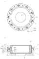
図1は、本実施形態に係るタイヤ成型金型用測定治具を示す。このタイヤ成型金型用測定治具は、機械構造用炭素鋼(例えば、S45C)、球状黒鉛鋳鉄(例えば、FCD450)等からなる有底筒状の治具本体1と、この治具本体1に取り付けられる、同様な材料からなる複数のブロック2とで構成されている。
FIG. 1 shows a measuring tool for a tire molding die according to this embodiment. The tire molding die measuring jig includes a bottomed
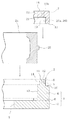
図2に示すように、治具本体1は一体的に形成した底面部3と筒状部4とからなる。
底面部3はドーナツ状で、中心孔5により軽量化が図られている。また底面部3の外周部上面には段部6が形成されている。
As shown in FIG. 2, the
The
筒状部4の上端部には環状凸部7が形成されている。
環状凸部7の外周面は、後述するブロック2を構成する側面部17の第1基準内面19を当接させて位置決めするための外周基準面8を構成している。外周基準面8には第1雌ネジ孔9が開口している。第1雌ネジ孔9は、後述するブロック2の側面部17を固定する際に利用される。また環状凸部7の外周側端面は環状上面10で構成されている。環状凸部7の上面は、ブロック2を構成する上面部18の基準下面21を当接させて位置決めするための基準上面11を構成している。基準上面11には、周方向に所定ピッチで第2雌ネジ孔12が開口している。第2雌ネジ孔12は、後述するブロック2の上面部18を固定する際に利用される。
An
The outer peripheral surface of the
筒状部4は、内周面側に、底面部3の段部6上面から上方に向かって形成される内周基準面13と、そこから上端に向かって形成される環状凸部7の内周面である内周逃がし面14とを有する。内周基準面13は、各セクタ24の外面を当接させて位置決めするために利用される。内周逃がし面14は、位置決めされたセクタ24の突条25の外面よりも外径側に形成されている。
The
また、筒状部4には、図1に示すように、周方向の複数箇所に外周面から第1段付き孔15aが形成されている。各第1段付き孔15aには第1ボルト15Aがそれぞれ挿通され、その雄ネジ部を後述するセクタ24の第1ネジ穴25aに螺合することによりセクタ24を固定できるようになっている。ここでは、第1段付き孔15aは周方向の18箇所に形成されている。また環状凸部7には、周方向の複数箇所に貫通孔15bがそれぞれ形成されている。
Moreover, as shown in FIG. 1, the
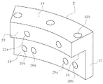
図2及び図3に示すように、ブロック2は、複数個が周方向に並設されて円筒状となる。各ブロック2は、側面部17と、その上端部から側方に延びる上面部18とで構成されている。
側面部17の内面は、前記治具本体1の筒状部4に形成される外周基準面8に当接する第1基準内面19を構成している。側面部17の両側には、前記筒状部4の各貫通孔15bに対応する位置に第2段付き孔20aがそれぞれ形成されている。この第2段付き孔20aから貫通孔15bを介して第2ボルト20Aの雄ネジ部をセクタ24の第2ネジ穴25bに螺合できるようになっている。また各第2段付き孔20aの周方向外側には、前記環状凸部7の第1雌ねじ孔9に対応する位置に第3段付き孔20bがそれぞれ形成されている。第3段付き孔20bには第3ボルト(図示せず)が配置され、その雄ネジ部が前記環状凸部7の第1雌ねじ孔9に螺合することにより治具本体1に対してブロック2をネジ止めできるようになっている。但し、治具本体1へのブロック2のネジ止め固定は、側面部17及び上面部18共に、2箇所に限らず、1箇所又は3箇所以上であっても構わない。
As shown in FIGS. 2 and 3, a plurality of
The inner surface of the
上面部18の下面は、前記治具本体1の環状凸部7の基準上面11に載置される基準下面21を構成している。上面部18には、外面から内面に貫通する第4段付き孔22aが両側にそれぞれ形成されている。第4段付き孔22aには第4ボルト22Aが配置され、その雄ネジ部が後述するセクタ24の第5雌ねじ孔25cに螺合することにより、セクタ24を位置決めできるようになっている。また上面部18には、上面から下面に貫通する第5段付き孔22bが3箇所に形成されている。これら第5段付き孔22bを利用して、治具本体1の筒状部4に対してブロック2をネジ止めすることができるようになっている。この上面部18でのネジ止めは、上面部18及び側面部17の外面からのネジ止めだけでは治具本体1への固定が不十分となってブロック2が傾くことを防止するために行う。また上面部18の内面は、後述するセクタ24の外周面に当接する第2基準内面23を構成している。
The lower surface of the
前記ブロック2では、第1基準内面19を前記治具本体1の外周基準面8に当接し、基準下面21を前記治具本体1の基準上面11に載置した状態で、側面部17の下端位置と治具本体1の環状上面10との間には隙間が形成されるようになっている。このため、ブロック2の第1基準内面19を、治具本体1の外周基準面8に対して正確に位置決めすることができる。
In the
前記構成の治具は、タイヤ成型金型のセクタ24を、タイヤ成型時の熱膨張分を考慮して周方向に一定の隙間を形成しつつ保持する際に利用される。
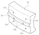
セクタ24は、アルミニウム又はアルミニウム合金からなり、周方向に複数個が並設されることにより形成された内周面で、未加硫のタイヤであるグリーンタイヤのトレッド部にトレッドパターンを形成する。図4に示すように、各セクタ24の外周面には、凸部の一形態である周方向に延びる突条25が形成されている。セクタ24の外周面には、第3雌ネジ孔25a、第4雌ねじ孔25b及び第5雌ねじ孔25cがそれぞれ形成されている。第3雌ねじ孔25aは、突条25の下方両側に配置され、前記第1ボルト15Aの雄ネジ部が螺合される。第4雌ねじ孔25bは、突条25の両端側に配置され、前記1組の貫通孔15bを介して第2ボルト20Aの雄ネジ部が螺合される。第5雌ねじ孔25cは、突条25の上方両側に配置され、第4ボルト22Aの雄ネジ部が螺合される。
The jig having the above-described configuration is used when the
The
前記治具へのセクタ24の位置決め(固定)は次のようにして行う。
すなわち、治具本体1の筒状部4の内周側にセクタ24を配置する。この場合、セクタ24は、予め外周方向に並設して環状に連なった状態としておく。セクタ24の外面には突条25が形成されているが、筒状部4の内周面は、セクタ24の突条25との干渉を回避するための内周逃がし面14で構成されている。つまり、セクタ24の配置で、治具本体1に対して上方側から組み付ける際、治具本体1に突条25が干渉する部位はない。したがって、環状に配置したセクタ24をそのまま治具本体1の筒状部4の内周側へと配置することができる。
Positioning (fixing) of the
That is, the
治具本体1にセクタ24が配置されれば、治具本体1の環状凸部7を利用してブロック2を組み付ける。このとき、治具本体1の外周基準面8にブロック2の第1基準内面19を当接させ、治具本体1の基準上面11にブロック2の基準下面21を載置する。これにより、ブロック2の第2基準内面23が、治具本体1の外周基準面8に対して正確に位置決めされ、第2基準内面23は前記内周基準面13と共にセクタ24の外周面に当接する。
If the
この状態で、各ボルトを締め付け、治具本体1に対してセクタ24及びブロック2を固定する。すなわち、ブロック2の側面部17に形成した第3段付き孔20bを介して第3ボルトを挿通し、その雄ネジ部を治具本体1の環状凸部7に形成した第1雌ねじ孔19に螺合する。これにより、治具本体1にブロック2が固定され、治具本体1の筒状部4(外周基準面8)に対してブロック2の第1基準内面19が位置決めされる。またブロック2の上面部18に形成した第5段付き孔22bを介して上面部18を治具本体1の環状凸部7(基準上面11)に固定する。このように、側面部17のみならず上面部18でもネジ止め固定したので、ブロック2の倒れを防止して取り付け状態を安定させることができる。またブロック2の第1基準内面19を治具本体1の外周基準面8に当接させることにより、上面部18の第2基準内面23の位置を治具本体1の内周基準面13と高精度に合致させることができる。したがって、セクタ24の外面の位置決めを適切に行うことが可能となる。なお、各セクタ24は周方向に所定の隙間が形成されるようにして取り付ける。
In this state, each bolt is tightened, and the
次に、図示しない隙間ゲージを使用して各セクタ24の隙間を測定する。そして、全ての隙間について測定が完了すれば、その測定値の合計を計算し、その合計値が予め設定した値に(所定公差の範囲内で)合致するか否かを判断する。合致していれば、9つのセクタ24のセットは所望の精度に形成されていることになり、タイヤ成型金型として使用する。合致していなければ、不良品と判断したり、一部のセクタ24の寸法調整を行って再度前述の測定を行ったりする。
Next, the gap of each
このように、前記構成の治具を使用してセクタ同士の隙間を測定することにより、測定結果を高精度なものとすることができる。ここで、以下のような2種類の他の構成の治具を使用する場合について検討してみる。
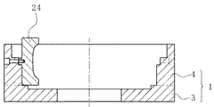
図5は、前記セクタ24の突条部を抑える部分、すなわちブロック2に相当する部分を全周に亘って除去した治具を示す。これによれば、治具に対するセクタ24の組付作業は容易であるものの、セクタ24の外面に当接する基準面の当接面積が小さくなり、測定精度が悪化する。
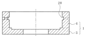
図6は、ブロック2を設けることなく環状溝28のみを形成した治具を示す。この治具では、そもそも外面に突条25を有するセクタ24を組み付けることができないという問題がある。
この点で、断面略L字形の取外可能なブロック2を備えた前記構成の治具によれば、セクタ24の組付作業を効率的に行うことができると共に、セクタ24間の隙間を高精度に測定することができるという利点がある。
Thus, the measurement result can be made highly accurate by measuring the gap between the sectors using the jig having the above-described configuration. Here, consider the case of using two types of jigs having other configurations as follows.
FIG. 5 shows a jig in which a portion for suppressing the protruding portion of the
FIG. 6 shows a jig in which only the
In this respect, according to the jig having the above-described configuration including the
なお、本発明は、前記実施形態に記載された構成に限定されるものではなく、種々の変更が可能である。 In addition, this invention is not limited to the structure described in the said embodiment, A various change is possible.
前記実施形態では、セクタ24は9分割で設けるようにしたが、7分割等、その分割数は自由に設定することができる。また各セクタ24のサイズは均等にしたが、必ずしも均等とする必要もなく、周長が相違していても構わない。
In the above embodiment, the
前記実施形態では、セクタ24の外面に凸部として突条25を形成するようにしたが、この凸部は必ずしも周方向につらなった突条25である必要はなく、2箇所の突起等で構成することも可能である。
In the above-described embodiment, the
前記実施形態では、治具本体1に対する各セクタ24の位置合わせをそれぞれに付与した番号に基づいて行うようにしたが、図7に示すように、いずれか一方に突起26、残る他方にこの突起26を配置可能な凹部27を設け、突起26と凹部27の位置を各セクタ24で相違させることにより、位置合わせするようにしてもよい。
In the above-described embodiment, the alignment of each
1…治具本体
2…ブロック
3…底面部
4…筒状部
5…中心孔
6…段部
7…環状凸部
8…外周基準面
9…第1雌ネジ孔
10…環状上面
11…基準上面
12…第2雌ネジ孔
13…内周基準面
14…内周逃がし面
15a…第1段付き孔
15A…第1ボルト
15b…貫通孔
16…第2ネジ孔
17…側面部
18…上面部
19…第1基準内面
20a…第2段付き孔
20A…第2ボルト
20b…第3段付き孔
21…基準下面
22a…第4段付き孔
22A…第4ボルト
22b…第5段付き孔
23…第2基準内面
24…セクタ
25…突条(凸部)
25a…第3雌ねじ孔
25b…第4雌ねじ孔
25c…第5雌ねじ孔
26…突起
27…凹部
28…環状溝
DESCRIPTION OF
25a ... 3rd
Claims (4)
筒状で、前記セクタの外面が当接可能な内周基準面と、前記セクタの凸部よりも外径側に形成されて前記凸部との接触を回避する内周逃がし面と、を有する治具本体と、
周方向に分割され、前記治具本体に着脱可能な複数のブロックと、
を備え、
前記ブロックは、前記治具本体の外周基準面に当接する側面部と、前記側面部から前記セクタの凸部の外面位置よりも内径側に延びる上面部とを備えたことを特徴とするタイヤ成型金型用測定治具。 A measuring jig for a tire molding die for guiding an outer peripheral surface side obtained by arranging a plurality of sectors having convex portions on an outer surface in a circumferential direction,
An inner peripheral reference surface that is cylindrical and capable of contacting the outer surface of the sector, and an inner peripheral relief surface that is formed on the outer diameter side of the convex portion of the sector and avoids contact with the convex portion. A jig body;
A plurality of blocks divided in the circumferential direction and detachable from the jig body;
With
The block includes a side surface portion that comes into contact with an outer peripheral reference surface of the jig body, and an upper surface portion that extends from the side surface portion toward an inner diameter side of an outer surface position of a convex portion of the sector. Measuring jig for molds.
前記各ブロックは、上面部が治具本体に位置決めされたセクタの外周面に当接する第2の内周基準面を、さらに有することを特徴とする請求項1に記載のタイヤ成型金型用測定治具。 The jig body further includes an outer peripheral reference surface for positioning by positioning an inner peripheral surface of each block,
2. The measurement for a tire molding die according to claim 1, wherein each of the blocks further includes a second inner peripheral reference surface abutting on an outer peripheral surface of a sector whose upper surface portion is positioned on the jig body. jig.
前記治具本体の内周基準面にセクタの外面を当接させて位置決めする工程と、
前記治具本体にブロックを固定してセクタの凸部を覆う工程と、
前記治具本体にセクタを固定する工程と、
前記治具本体に固定されることにより隣接するセクタ間に形成される隙間を測定する工程と、
を実行することを特徴とするタイヤ成型金型用測定治具の使用方法。 It is a usage method of the measuring tool for tire molding dies according to any one of claims 1 to 3,
The step of abutting and positioning the outer surface of the sector on the inner peripheral reference surface of the jig body;
Fixing the block to the jig body and covering the convex portion of the sector;
Fixing the sector to the jig body;
Measuring a gap formed between adjacent sectors by being fixed to the jig body;
A method of using a measuring tool for a tire mold, characterized in that
Priority Applications (1)
| Application Number | Priority Date | Filing Date | Title |
|---|---|---|---|
| JP2013271161A JP6174994B2 (en) | 2013-12-27 | 2013-12-27 | Measuring jig for tire mold and method of using the same |
Applications Claiming Priority (1)
| Application Number | Priority Date | Filing Date | Title |
|---|---|---|---|
| JP2013271161A JP6174994B2 (en) | 2013-12-27 | 2013-12-27 | Measuring jig for tire mold and method of using the same |
Publications (2)
| Publication Number | Publication Date |
|---|---|
| JP2015123717A true JP2015123717A (en) | 2015-07-06 |
| JP6174994B2 JP6174994B2 (en) | 2017-08-02 |
Family
ID=53534786
Family Applications (1)
| Application Number | Title | Priority Date | Filing Date |
|---|---|---|---|
| JP2013271161A Active JP6174994B2 (en) | 2013-12-27 | 2013-12-27 | Measuring jig for tire mold and method of using the same |
Country Status (1)
| Country | Link |
|---|---|
| JP (1) | JP6174994B2 (en) |
Citations (5)
| Publication number | Priority date | Publication date | Assignee | Title |
|---|---|---|---|---|
| JP2002257537A (en) * | 2001-03-02 | 2002-09-11 | Sumitomo Rubber Ind Ltd | Tread segment inner surface unevenness measuring device and measuring method |
| JP2006289902A (en) * | 2005-04-14 | 2006-10-26 | Sumitomo Rubber Ind Ltd | Roundness measuring device for inner peripheral surface of tire vulcanizing mold |
| JP2008023722A (en) * | 2006-07-18 | 2008-02-07 | Sumitomo Rubber Ind Ltd | Mold for tire |
| JP2009119819A (en) * | 2007-11-19 | 2009-06-04 | Sumitomo Rubber Ind Ltd | Apparatus and method for cleaning mold for tire |
| JP2013144414A (en) * | 2012-01-16 | 2013-07-25 | Sumitomo Rubber Ind Ltd | Tire mold |
-
2013
- 2013-12-27 JP JP2013271161A patent/JP6174994B2/en active Active
Patent Citations (5)
| Publication number | Priority date | Publication date | Assignee | Title |
|---|---|---|---|---|
| JP2002257537A (en) * | 2001-03-02 | 2002-09-11 | Sumitomo Rubber Ind Ltd | Tread segment inner surface unevenness measuring device and measuring method |
| JP2006289902A (en) * | 2005-04-14 | 2006-10-26 | Sumitomo Rubber Ind Ltd | Roundness measuring device for inner peripheral surface of tire vulcanizing mold |
| JP2008023722A (en) * | 2006-07-18 | 2008-02-07 | Sumitomo Rubber Ind Ltd | Mold for tire |
| JP2009119819A (en) * | 2007-11-19 | 2009-06-04 | Sumitomo Rubber Ind Ltd | Apparatus and method for cleaning mold for tire |
| JP2013144414A (en) * | 2012-01-16 | 2013-07-25 | Sumitomo Rubber Ind Ltd | Tire mold |
Also Published As
| Publication number | Publication date |
|---|---|
| JP6174994B2 (en) | 2017-08-02 |
Similar Documents
| Publication | Publication Date | Title |
|---|---|---|
| US9879966B2 (en) | Fixture | |
| US20150308482A1 (en) | Resin component fastener structure and molding device therefor | |
| JP6174994B2 (en) | Measuring jig for tire mold and method of using the same | |
| CN108426511A (en) | A kind of depth measurement tools of cambered surface stepped hole | |
| KR101214335B1 (en) | Thread ring gauge | |
| CN202442660U (en) | Measuring caliper | |
| JP6194230B2 (en) | Measuring jig for tire mold and method of using the same | |
| CN107614867A (en) | The impeller of fluid machinery with detachable blade | |
| CN107063079B (en) | Measure relative concentricity deviation in confined space between two hoop elements | |
| CN106441025B (en) | The right-angle side pitch-row survey tool of structure hole on parts rake | |
| JP2010155410A (en) | Mold for vulcanizing tire | |
| JP5285268B2 (en) | Mold for molding | |
| CN210004926U (en) | measuring tools special for discontinuous inner arc | |
| KR101961777B1 (en) | Electrical probe and jig for the same | |
| CN205120939U (en) | A device for measuring superconducting magnet magnetic field | |
| KR19980087524A (en) | Method of Adjusting Plate Thickness of Molding Substrate in Substrate Molding Mold and Substrate Molding Mold | |
| JP2017173024A (en) | measuring device | |
| CN210497963U (en) | High-precision stamping forming tool | |
| JP3217843U (en) | Tire vulcanization mold equipment | |
| CN114199107A (en) | Device and method for detecting wall thickness of cylinder of piston type aero-engine | |
| CN104999294B (en) | Quick high accuracy positioning unit | |
| CN104625679A (en) | Interconvertible three-direction adjustment device | |
| CN223870046U (en) | An integrated standard assembly for calibrating a wheel tread shape tester | |
| JP5487331B1 (en) | Master tire assembly, basic data creation method using the same, and calibration method for uniformity measuring device | |
| CN204064188U (en) | Interchangeable combined clearance measurement clearance gauge |
Legal Events
| Date | Code | Title | Description |
|---|---|---|---|
| A621 | Written request for application examination |
Free format text: JAPANESE INTERMEDIATE CODE: A621 Effective date: 20161017 |
|
| A977 | Report on retrieval |
Free format text: JAPANESE INTERMEDIATE CODE: A971007 Effective date: 20170628 |
|
| TRDD | Decision of grant or rejection written | ||
| A01 | Written decision to grant a patent or to grant a registration (utility model) |
Free format text: JAPANESE INTERMEDIATE CODE: A01 Effective date: 20170704 |
|
| A61 | First payment of annual fees (during grant procedure) |
Free format text: JAPANESE INTERMEDIATE CODE: A61 Effective date: 20170707 |
|
| R150 | Certificate of patent or registration of utility model |
Ref document number: 6174994 Country of ref document: JP Free format text: JAPANESE INTERMEDIATE CODE: R150 |
|
| S533 | Written request for registration of change of name |
Free format text: JAPANESE INTERMEDIATE CODE: R313533 |
|
| R371 | Transfer withdrawn |
Free format text: JAPANESE INTERMEDIATE CODE: R371 |
|
| S533 | Written request for registration of change of name |
Free format text: JAPANESE INTERMEDIATE CODE: R313533 |
|
| R350 | Written notification of registration of transfer |
Free format text: JAPANESE INTERMEDIATE CODE: R350 |
|
| R250 | Receipt of annual fees |
Free format text: JAPANESE INTERMEDIATE CODE: R250 |
|
| R250 | Receipt of annual fees |
Free format text: JAPANESE INTERMEDIATE CODE: R250 |
|
| R250 | Receipt of annual fees |
Free format text: JAPANESE INTERMEDIATE CODE: R250 |
|
| R250 | Receipt of annual fees |
Free format text: JAPANESE INTERMEDIATE CODE: R250 |
|
| R250 | Receipt of annual fees |
Free format text: JAPANESE INTERMEDIATE CODE: R250 |
|
| R250 | Receipt of annual fees |
Free format text: JAPANESE INTERMEDIATE CODE: R250 |