JP2015123782A - Pneumatic tire and method for manufacturing the same - Google Patents
Pneumatic tire and method for manufacturing the same Download PDFInfo
- Publication number
- JP2015123782A JP2015123782A JP2013267722A JP2013267722A JP2015123782A JP 2015123782 A JP2015123782 A JP 2015123782A JP 2013267722 A JP2013267722 A JP 2013267722A JP 2013267722 A JP2013267722 A JP 2013267722A JP 2015123782 A JP2015123782 A JP 2015123782A
- Authority
- JP
- Japan
- Prior art keywords
- curved surface
- pneumatic tire
- main groove
- curvature
- radius
- Prior art date
- Legal status (The legal status is an assumption and is not a legal conclusion. Google has not performed a legal analysis and makes no representation as to the accuracy of the status listed.)
- Granted
Links
Images




Landscapes
- Tires In General (AREA)
- Tyre Moulding (AREA)
Abstract
【課題】主溝の底部にクラックが発生しにくい構造を有する空気入りタイヤを提供する。
【解決手段】タイヤ周方向に延びる主溝2を備える。主溝2を構成する両側の内側面と底面との接続部分は第1曲面11と第2曲面12とからなる。第1曲面11は、縦断面形状が曲率半径R1で、底面との境界位置が、溝部2の中心位置を超えて反対側に延びる。第2曲面12は、縦断面形状が曲率半径R1よりも小さい曲率半径R2である。第1曲面11と第2曲面12とはタイヤ周方向に沿って交互に配置される。
【選択図】図1A pneumatic tire having a structure in which cracks are unlikely to occur at the bottom of a main groove is provided.
A main groove 2 extending in a tire circumferential direction is provided. A connecting portion between the inner side surface and the bottom surface on both sides constituting the main groove 2 includes a first curved surface 11 and a second curved surface 12. The first curved surface 11 has a longitudinal cross-sectional shape with a radius of curvature R <b> 1, and a boundary position with the bottom surface extends beyond the center position of the groove 2 to the opposite side. The second curved surface 12 has a curvature radius R2 whose longitudinal cross-sectional shape is smaller than the curvature radius R1. The first curved surface 11 and the second curved surface 12 are alternately arranged along the tire circumferential direction.
[Selection] Figure 1
Description
本発明は、空気入りタイヤ及びその製造方法に関するものである。 The present invention relates to a pneumatic tire and a method for manufacturing the same.
従来、空気入りタイヤとして、次のような構成のものが公知である。
特許文献1には、主溝によって区画されたリブの表面幅が基部幅よりも大きく、少なくとも片方の側壁部には、主溝の底部に接続するリブの基部に近いほど深さと幅とが広がる切込み部を形成した構成が開示されている。
特許文献2には、主溝の溝壁が周方向に直線となる直線上領域と、ジグザグとなるジグザグ下領域とを含む構成が開示されている。
特許文献3には、主溝がタイヤ幅方向に振幅するジグザグ形状を有し、その屈曲部にさらにタイヤ幅方向に窪んだ剛性調整部を形成した構成が開示されている。
特許文献4には、主溝の中心をセカンドリブ側に変位させ、トレッド面からのセカンドリブ側溝壁の傾斜角度をショルダーリブ側溝壁よりも小さくした構成が開示されている。
Conventionally, a pneumatic tire having the following configuration is known.
In Patent Document 1, the surface width of the rib partitioned by the main groove is larger than the base width, and the depth and width of at least one of the side walls expands closer to the base of the rib connected to the bottom of the main groove. A configuration in which a cut portion is formed is disclosed.
しかしながら、特許文献1では、切込み部が形成されてはいるものの、主溝の底部に接続されるリブの基部側の縦断面形状を構成する円弧の曲率半径についての言及はない。この曲率半径を大きくするための工夫がないと応力集中によりクラックが発生しやすいという問題は解決しない。
特許文献2では、ジグザグ下方領域の縦断面形状を構成する円弧の曲率半径についての言及はなく、前記特許文献1と同様に、クラックが発生しやすいという問題は解決しない。
特許文献3では、タイヤ周方向に不連続で形成されているため、この部分に応力が集中しやすく、クラックが発生しやすいという問題がある。
特許文献4では、主溝のショルダーリブ側溝壁の基部側では縦断面形状を構成する円弧の曲率半径は大きくできるものの、反対側のセカンドリブ側溝壁では逆に通常の値よりも小さくなってしまい、より一層クラックが発生しやすくなるという問題がある。
However, in patent document 1, although the notch part is formed, there is no mention about the curvature radius of the circular arc which comprises the longitudinal cross-sectional shape of the base part side of the rib connected to the bottom part of a main groove. Without the idea to increase the radius of curvature, the problem that cracks are likely to occur due to stress concentration cannot be solved.
In
In
In
本発明は、主溝の底部にクラックが発生しにくい構造を有する空気入りタイヤ及びその製造方法を提供することを課題とする。 This invention makes it a subject to provide the pneumatic tire which has a structure where a crack is hard to generate | occur | produce at the bottom part of a main groove, and its manufacturing method.
本発明は、前記課題を解決するための手段として、
トレッド面に形成される溝部を備えた空気入りタイヤであって、
前記主溝を構成する両側の内側面の内方側部分は第1曲面と第2曲面とからなり、
前記第1曲面は、縦断面形状が曲率半径R1で、内方側での終端位置が、溝部の中心位置を超えて反対側に延び、
前記第2曲面は、縦断面形状が前記曲率半径R1よりも小さい曲率半径R2であり、
前記第1曲面と前記第2曲面とはタイヤ周方向に沿って交互に配置されるものである。
As a means for solving the above problems, the present invention provides:
A pneumatic tire having a groove formed on a tread surface,
The inner side portions of the inner side surfaces on both sides constituting the main groove are composed of a first curved surface and a second curved surface,
The first curved surface has a longitudinal cross-sectional shape with a radius of curvature R1 and an end position on the inner side extends beyond the center position of the groove portion to the opposite side,
The second curved surface has a curvature radius R2 whose longitudinal cross-sectional shape is smaller than the curvature radius R1,
The first curved surface and the second curved surface are alternately arranged along the tire circumferential direction.
この構成により、少なくとも第1曲面では曲率半径を十分に大きくすることができるので、応力集中を緩和してクラックの発生を防止することができる。 With this configuration, since the radius of curvature can be sufficiently increased at least on the first curved surface, the stress concentration can be relaxed and the occurrence of cracks can be prevented.
前記第2曲面は、前記内側面から窪んだ凹状に形成されるのが好ましい。 The second curved surface is preferably formed in a concave shape recessed from the inner side surface.
この構成により、第1曲面だけでなく、第2曲面でも曲率半径を十分に大きくすることができるので、主溝の底部の全体に亘ってクラックの発生を防止することができる。 With this configuration, the radius of curvature can be sufficiently increased not only in the first curved surface but also in the second curved surface, so that generation of cracks can be prevented over the entire bottom portion of the main groove.
前記溝部の中心位置から前記境界位置までの寸法は、前記内側面からの前記第2曲面の深さ寸法と同一であるのが好ましい。 It is preferable that the dimension from the center position of the groove part to the boundary position is the same as the depth dimension of the second curved surface from the inner side surface.
この構成により、主溝の底部の両側で、ほぼ同じ曲率半径となる第1曲面を形成することができ、応力集中をバランス良く緩和し、クラックの発生をより一層適切に防止することが可能となる。 With this configuration, it is possible to form the first curved surface having substantially the same radius of curvature on both sides of the bottom of the main groove, and it is possible to alleviate stress concentration in a well-balanced manner and more appropriately prevent the occurrence of cracks. Become.
前記第1曲面の内方側終端位置と前記第2曲面の内方側終端位置とを合致させるのが好ましい。 It is preferable that the inner end position of the first curved surface is matched with the inner end position of the second curved surface.
この構成により、主溝の幅寸法を抑制しつつクラックの発生を効果的に防止することができる。 With this configuration, the occurrence of cracks can be effectively prevented while suppressing the width dimension of the main groove.
前記第1曲面と前記第2曲面の内方側終端位置は、前記タイヤの周方向に延びるsin波形を構成するのが好ましい。 It is preferable that the inward end positions of the first curved surface and the second curved surface constitute a sin waveform extending in the circumferential direction of the tire.
この構成により、主溝の底部両側に第1曲面と第2曲面とをバランス良く配置することができ、より一層クラックの発生を抑制することが可能となる。 With this configuration, the first curved surface and the second curved surface can be arranged with good balance on both sides of the bottom of the main groove, and the generation of cracks can be further suppressed.
また本発明は、前記課題を解決するための手段として、
タイヤ周方向に延びる主溝を備えた空気入りタイヤの製造方法であって、
前記主溝を構成する両側の内側面と底面との接続部分に第1曲面と第2曲面とを形成し、前記第1曲面は、縦断面形状が曲率半径R1で、前記底面との境界位置が、溝部の中心位置を超えて反対側に延び、前記第2曲面は、縦断面形状が前記曲率半径R1よりも小さい曲率半径R2であり、前記第1曲面と前記第2曲面とはタイヤ周方向に沿って交互に配置するものである。
Further, the present invention provides a means for solving the above-described problems,
A method of manufacturing a pneumatic tire having a main groove extending in the tire circumferential direction,
A first curved surface and a second curved surface are formed at a connection portion between the inner side surface and the bottom surface on both sides constituting the main groove, and the first curved surface has a longitudinal radius of curvature R1 and a boundary position with the bottom surface. However, the second curved surface has a curvature radius R2 whose longitudinal cross-sectional shape is smaller than the curvature radius R1, and the first curved surface and the second curved surface are tire circumferences. They are arranged alternately along the direction.
本発明によれば、少なくとも第1曲面は、底面との境界位置が溝部の中心位置を超えて反対側に延びる、縦断面形状が曲率半径R1に形成されているので、応力集中が緩和され、クラックの発生を十分に抑制することができる。 According to the present invention, at least the first curved surface has a longitudinal cross-sectional shape with a curvature radius R1 that extends to the opposite side beyond the center position of the groove portion at the boundary position with the bottom surface, so stress concentration is relieved, The occurrence of cracks can be sufficiently suppressed.
以下、本発明に係る実施形態を添付図面に従って説明する。なお、以下の説明では、必要に応じて特定の方向や位置を示す用語(例えば、「上」、「下」、「側」、「端」を含む用語)を用いるが、それらの用語の使用は図面を参照した発明の理解を容易にするためであって、それらの用語の意味によって本発明の技術的範囲が限定されるものではない。また以下の説明は、本質的に例示に過ぎず、本発明、その適用物、あるいは、その用途を制限することを意図するものではない。さらに図面は模式的なものであり、各寸法の比率等は現実のものとは相違している。 Embodiments according to the present invention will be described below with reference to the accompanying drawings. In the following description, terms indicating specific directions and positions (for example, terms including “up”, “down”, “side”, “end”) are used as necessary. Is for facilitating understanding of the invention with reference to the drawings, and the technical scope of the present invention is not limited by the meaning of these terms. Further, the following description is merely illustrative in nature and is not intended to limit the present invention, its application, or its use. Further, the drawings are schematic, and the ratio of each dimension is different from the actual one.
図1は、本実施形態に係るタイヤのトレッド面1の一部を示す展開図である。このトレッド面1には、タイヤ周方向に延びる複数本の主溝2によって複数の陸部(リブ)3が形成されている。図1には、1本の主溝2とその両側に位置する第1陸部4及び第2陸部5とが図示されている。
FIG. 1 is a development view showing a part of a tread surface 1 of a tire according to the present embodiment. A plurality of land portions (ribs) 3 are formed on the tread surface 1 by a plurality of
図2、詳しくは図3に示すように、主溝2の外方側領域は、トレッド面1から内方側に向かうに従って徐々に主溝2の中心線C側へと傾斜する、第1陸部4の内側面(第1傾斜面6)と、第2陸部5の内側面(第2傾斜面7)とで構成されている。図1に示すように、主溝2の内方側領域はタイヤ周方向に交互に配置される第1領域8と第2領域9とで構成されている。
As shown in FIG. 2 and specifically FIG. 3, the outer side region of the
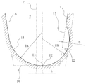
第1領域8では、図2(a)、詳しくは図3に示す第1陸部4の内側面が、前記第1傾斜面6と、主溝2の最も深い仮想底面10(図3中、2点鎖線で示す)を通る円周面とに接する第1曲面11で構成されている。第1曲面11は、タイヤの子午面での縦断面形状が曲率半径RAであり、この曲率半径RAはタイヤ周方向に位置ずれすることにより増減している。すなわち、曲率半径RAの円弧の内方側終端位置E1は前記仮想底面10に位置し、図1に示すように、この位置は主溝2の中心線Cに対してsin波形の半波を形成するように増減する。またその振幅は仮想底面10の幅寸法の1/10から1/4の範囲に設定する。図1のA−A線断面すなわち図2(a)及び図3に示すように、第1曲面11は、内方側終端位置E1が主溝2の中心線Cを超えて反対側に最も膨らんだ曲率半径RA1となっている。図1のB−B線断面すなわち図2(b)に示すように、第1曲面11は、内方側終端位置E1が主溝2の中心線C上に位置する最も小さい曲率半径RA2となっている。そして、縦断面での円弧の曲率半径がRA1からRA2へと徐々に小さくなるように曲面状となっている。
In the
また、第1領域8では、第2陸部5の内側面に凹状に窪んだ第2曲面12が形成されている。第2曲面12は、曲率半径RBの球面の一部で構成されている。したがって、タイヤ周方向に位置をずらせた各位置での縦断面形状は、図1のA−A線断面すなわち図2(a)に於ける最大曲率半径RB1から、図1のB−B線断面すなわち図2(b)に於ける最小曲率半径RB2へと徐々に変化する。そして、これら各縦断面に形成される円弧は、主溝2の仮想底面10と接し、前記第1曲面11の内方側終端位置E1で終端するように形成されている。また第2曲面12の図1のA−A線断面に於ける仮想内側面13(図2中、2点鎖線で示す)からの深さ寸法Dは、前記主溝2の中心線Cから前記第1曲面11の内方側終端位置E2までの寸法Lと同一としている。
In the
第2領域9では、図2(c)に示すように、前記第1領域8とは逆に、第1陸部4の内側面の下方側領域に第2曲面12が形成され、第2陸部5の内側面の下方側領域に第1曲面11が形成されている。つまり、第2領域9は、前記第1領域8とは主溝2の中心線Cを挟んで面対称な構成となっている。そして、第1領域8及び第2領域9で、主溝2の底部での第1曲面11の内方側終端位置E1及び第2曲面12の内方側終端位置E2がsin波形の1周期分が形成される。このsin波形は、タイヤ周方向の全周に亘って延び、環状につながっている。ここでは、周期は振幅の12倍から24倍でつながっている。
In the
このように、前記構成の主溝2では、対向する陸部3の一方に、トレッド面1に同一幅寸法で開口する従来構成の主溝2に比べて十分に大きな曲率半径RAの第1曲面11を有する。また、第1曲面11とは反対側の陸部3にも球面の一部を構成する第2曲面12が形成されることにより曲率半径が大きくなった円弧となっている。したがって、従来の曲率半径が小さい第1曲面11のように、一部に応力が集中してクラックが発生する心配がない。また、第2曲面12が形成されることによって陸部3の薄くなった部分は、タイヤ周方向に千鳥状に配列されることになる。このため、陸部3には、タイヤ周方向に多数の第2曲面12が形成されているにも拘わらず、その剛性の低下を抑えることができる。しかも、主溝2の幅寸法がタイヤ周方向のいずれの位置であっても狭くなることがなく、所望の排水性を維持することができる。
As described above, in the
比較例1及び2に係るタイヤと、実施例1、2及び3に係るタイヤとで、主溝2の底部にクラックが発生したか否かについて比較実験を行った。ここでは、サイズが275/80R22.5で、空気圧を900kPaとしたタイヤを、タイヤ負荷4485kg、時速80kmで15万kmの走行後に、主溝2の底部にクラックが発生しているか否かを目視により確認した。
A comparative experiment was conducted as to whether or not a crack occurred at the bottom of the
比較例1は、図5(a)に示すように、主溝2の底部両側での縦断面形状がそれぞれ曲率半径3.5mmの円弧で構成されたタイヤである。
比較例2は、図5(b)に示すように、主溝2の底部片側にのみ内側面から窪んだ曲面15を形成することにより、底部の両側に、曲率半径3.5mmの円弧と、5.5mmの円弧とをそれぞれ形成したタイヤである。
実施例1は、図5(c)に示すように、主溝2の底部両側に千鳥状に、対向部分に比べて曲率半径の大きな曲面16を形成することにより、底部の両側に、曲率半径2.5mmの円弧と、4.5mmの円弧とをそれぞれ形成したタイヤである。
実施例2は、図5(d)に示すように、主溝2の底部両側に千鳥状に内側面から窪んだ第2曲面12を形成することにより、底部の両側に、曲率半径3.5mmの円弧と、5.5mmの円弧とをそれぞれ形成したタイヤである。但し、タイヤ周方向に沿って、第1曲面11同士が対向する領域と、第1曲面11と第2曲面12が対向する領域とが交互に配置されている。
実施例3は、図5(e)に示すように、主溝2の底部両側に千鳥状に内側面から窪んだ第2曲面12を形成することにより、底部の両側に、曲率半径3.5mmの円弧と、5.5mmの円弧とをそれぞれ形成したタイヤである。実施例3では、実施例2とは異なり、第1曲面11同士が対向する領域はなく、第1曲面11と第2曲面12が対向する領域とが、タイヤ周方向に第1曲面11と第2曲面12を入れ替えながら配置されている。
As shown in FIG. 5A, Comparative Example 1 is a tire in which the longitudinal cross-sectional shape on both sides of the bottom of the
In Comparative Example 2, as shown in FIG. 5 (b), by forming a
In the first embodiment, as shown in FIG. 5 (c), a curved surface 16 having a larger radius of curvature than the opposite portion is formed in a staggered manner on both sides of the bottom of the
In the second embodiment, as shown in FIG. 5 (d), by forming the second
In Example 3, as shown in FIG. 5 (e), by forming the second
また評価基準は以下の通りである。
◎:15万km走行後においてもクラックが発生しなかった
○:15万km走行後に許容クラックが発生した
△:13万km走行後にクラックが発生した
×:12万km走行後にクラックが発生した
The evaluation criteria are as follows.
◎: No crack occurred after running 150,000 km ○: Permissible crack occurred after running 150,000 km △: Crack occurred after running 130,000 km ×: Crack occurred after running 120,000 km

表1から明らかなように、実施例1のタイヤであれば、主溝2の底部でのクラックの発生を走行距離13万kmまで延ばすことができた。これは、比較例1に比べて曲率半径の大きくなった曲面をタイヤ周方向に沿って千鳥状に配置することにより剛性バランスが改善したためであると考えられる。また実施例2のタイヤであれば、15万km走行しても主溝2の底部で発生するクラックは許容可能な程度のものに抑えることができた。これは、タイヤ幅方向の片側に窪みによってより大きな曲率半径を有する第2曲面12を形成したためであると考えられる。さらに実施例3のタイヤであれば、15万km走行しても主溝2の底部にはクラックは発生しなかった。これは、第2曲面12をタイヤ周方向に千鳥状に配置して連続させることにより、より一層効果的に応力集中を緩和し、剛性バランスを改善することができたためであると考えられる。
As can be seen from Table 1, with the tire of Example 1, the occurrence of cracks at the bottom of the
なお、本発明は、前記実施形態に記載された構成に限定されるものではなく、種々の変更が可能である。
例えば、前記実施形態では、トレッド面1に主溝2のみが形成されたタイヤについて説明したが、前記主溝2に交差してタイヤ幅方向に延びる横溝を有することにより複数のブロックが形成されたタイヤであっても同様に第1曲面11及び第2曲面12からなる構成を採用することができる。この場合、横溝を構成する両ブロックの内側面に第1曲面11及び第2曲面12をそれぞれ形成するようにしてもよい。
In addition, this invention is not limited to the structure described in the said embodiment, A various change is possible.
For example, in the above-described embodiment, a tire in which only the
また前記実施形態では、主溝2を、底部には平坦部分(タイヤ周方向に延びる円周面)のない構造としたが、図4に示すように、平坦部14を有するように構成することも可能である。すなわち、第1曲面11の内方側終端位置E1と第2曲面12の内方側終端位置E2とが一致せず、幅方向に一定間隔で離れさせることにより、一定幅寸法の帯状でsin波形を形成する平坦部14を形成してもよい。
Moreover, in the said embodiment, although the
本発明に係る空気入りタイヤは、特にトラックやバス等の高荷重タイヤとして使用するのに適している。 The pneumatic tire according to the present invention is particularly suitable for use as a high-load tire such as a truck or a bus.
1…トレッド面
2…主溝(溝部)
3…陸部(リブ)
4…第1陸部(リブ)
5…第2陸部(リブ)
6…第1傾斜面
7…第2傾斜面
8…第1領域
9…第2領域
10…仮想底面
11…第1曲面
12…第2曲面
13…仮想内側面
14…平坦部
1 ... Tread
3 ... Land (rib)
4 ... 1st land (rib)
5 ... Second land (rib)
DESCRIPTION OF
Claims (6)
前記溝部を構成する両側の内側面の内方側部分は第1曲面と第2曲面とからなり、
前記第1曲面は、縦断面形状が曲率半径R1で、内方側での終端位置が、溝部の中心位置を超えて反対側に延び、
前記第2曲面は、縦断面形状が前記曲率半径R1よりも小さい曲率半径R2であり、
前記第1曲面と前記第2曲面とはタイヤ周方向に沿って交互に配置されることを特徴とする空気入りタイヤ。 A pneumatic tire having a groove formed on a tread surface,
The inner side portions of the inner side surfaces on both sides constituting the groove part are composed of a first curved surface and a second curved surface,
The first curved surface has a longitudinal cross-sectional shape with a radius of curvature R1 and an end position on the inner side extends beyond the center position of the groove portion to the opposite side,
The second curved surface has a curvature radius R2 whose longitudinal cross-sectional shape is smaller than the curvature radius R1,
The pneumatic tire according to claim 1, wherein the first curved surface and the second curved surface are alternately arranged along a tire circumferential direction.
前記溝部を構成する両側の内側面の内方側部分は第1曲面と第2曲面とからなり、前記第1曲面は、縦断面形状が曲率半径R1で、前記底面との境界位置が、溝部の中心位置を超えて反対側に延び、前記第2曲面は、縦断面形状が前記曲率半径R1よりも小さい曲率半径R2であり、前記第1曲面と前記第2曲面とはタイヤ周方向に沿って交互に配置することを特徴とする空気入りタイヤの製造方法。 A method for manufacturing a pneumatic tire having a groove formed on a tread surface,
The inner side portions of the inner side surfaces on both sides constituting the groove portion are composed of a first curved surface and a second curved surface, and the first curved surface has a longitudinal sectional shape with a radius of curvature R1 and a boundary position with the bottom surface is a groove portion. The second curved surface has a curvature radius R2 whose longitudinal cross-sectional shape is smaller than the curvature radius R1, and the first curved surface and the second curved surface are along the tire circumferential direction. And a method for manufacturing a pneumatic tire, wherein the tires are alternately arranged.
Priority Applications (1)
| Application Number | Priority Date | Filing Date | Title |
|---|---|---|---|
| JP2013267722A JP6228001B2 (en) | 2013-12-25 | 2013-12-25 | Pneumatic tire and manufacturing method thereof |
Applications Claiming Priority (1)
| Application Number | Priority Date | Filing Date | Title |
|---|---|---|---|
| JP2013267722A JP6228001B2 (en) | 2013-12-25 | 2013-12-25 | Pneumatic tire and manufacturing method thereof |
Publications (2)
| Publication Number | Publication Date |
|---|---|
| JP2015123782A true JP2015123782A (en) | 2015-07-06 |
| JP6228001B2 JP6228001B2 (en) | 2017-11-08 |
Family
ID=53534834
Family Applications (1)
| Application Number | Title | Priority Date | Filing Date |
|---|---|---|---|
| JP2013267722A Active JP6228001B2 (en) | 2013-12-25 | 2013-12-25 | Pneumatic tire and manufacturing method thereof |
Country Status (1)
| Country | Link |
|---|---|
| JP (1) | JP6228001B2 (en) |
Cited By (4)
| Publication number | Priority date | Publication date | Assignee | Title |
|---|---|---|---|---|
| WO2022145151A1 (en) * | 2020-12-28 | 2022-07-07 | 住友ゴム工業株式会社 | Tire |
| JP2022103502A (en) * | 2020-12-28 | 2022-07-08 | 住友ゴム工業株式会社 | tire |
| JP2022103500A (en) * | 2020-12-28 | 2022-07-08 | 住友ゴム工業株式会社 | tire |
| JP2022103503A (en) * | 2020-12-28 | 2022-07-08 | 住友ゴム工業株式会社 | tire |
Citations (1)
| Publication number | Priority date | Publication date | Assignee | Title |
|---|---|---|---|---|
| JP2012001075A (en) * | 2010-06-16 | 2012-01-05 | Yokohama Rubber Co Ltd:The | Pneumatic tire |
-
2013
- 2013-12-25 JP JP2013267722A patent/JP6228001B2/en active Active
Patent Citations (1)
| Publication number | Priority date | Publication date | Assignee | Title |
|---|---|---|---|---|
| JP2012001075A (en) * | 2010-06-16 | 2012-01-05 | Yokohama Rubber Co Ltd:The | Pneumatic tire |
Cited By (7)
| Publication number | Priority date | Publication date | Assignee | Title |
|---|---|---|---|---|
| WO2022145151A1 (en) * | 2020-12-28 | 2022-07-07 | 住友ゴム工業株式会社 | Tire |
| JP2022103502A (en) * | 2020-12-28 | 2022-07-08 | 住友ゴム工業株式会社 | tire |
| JP2022103500A (en) * | 2020-12-28 | 2022-07-08 | 住友ゴム工業株式会社 | tire |
| JP2022103503A (en) * | 2020-12-28 | 2022-07-08 | 住友ゴム工業株式会社 | tire |
| JP7613100B2 (en) | 2020-12-28 | 2025-01-15 | 住友ゴム工業株式会社 | tire |
| JP7613101B2 (en) | 2020-12-28 | 2025-01-15 | 住友ゴム工業株式会社 | tire |
| JP7613102B2 (en) | 2020-12-28 | 2025-01-15 | 住友ゴム工業株式会社 | tire |
Also Published As
| Publication number | Publication date |
|---|---|
| JP6228001B2 (en) | 2017-11-08 |
Similar Documents
| Publication | Publication Date | Title |
|---|---|---|
| JP6317140B2 (en) | Pneumatic tire | |
| US20180162176A1 (en) | Pneumatic tire | |
| JP6228001B2 (en) | Pneumatic tire and manufacturing method thereof | |
| US20180147894A1 (en) | Pneumatic tire | |
| JP2018083585A (en) | Rough terrain tires | |
| JP2011183994A (en) | Pneumatic tire | |
| US9370972B2 (en) | Tire having circumferential groove formed with one intra-groove | |
| JP2010116112A (en) | Pneumatic tire | |
| JP2013180707A (en) | Pneumatic tire | |
| JP5749441B2 (en) | Pneumatic tire | |
| JP2020015437A (en) | Pneumatic tire | |
| JP2009202639A (en) | Pneumatic tire | |
| JP2014031107A (en) | Pneumatic tire | |
| WO2015178152A1 (en) | Pneumatic tire | |
| JP2013139164A (en) | Pneumatic tire | |
| JP2011245996A (en) | Pneumatic tire | |
| JP2014118016A (en) | Pneumatic tire | |
| JP2010247714A (en) | Tire | |
| JP2017100648A (en) | Pneumatic tire | |
| JP2018008601A (en) | tire | |
| JP6158594B2 (en) | tire | |
| JP2013035344A (en) | Tire | |
| JP2019043310A (en) | Pneumatic tire | |
| CN112937221A (en) | Pneumatic tire | |
| JP5753038B2 (en) | tire |
Legal Events
| Date | Code | Title | Description |
|---|---|---|---|
| A621 | Written request for application examination |
Free format text: JAPANESE INTERMEDIATE CODE: A621 Effective date: 20161115 |
|
| A977 | Report on retrieval |
Free format text: JAPANESE INTERMEDIATE CODE: A971007 Effective date: 20170621 |
|
| A131 | Notification of reasons for refusal |
Free format text: JAPANESE INTERMEDIATE CODE: A131 Effective date: 20170627 |
|
| A521 | Request for written amendment filed |
Free format text: JAPANESE INTERMEDIATE CODE: A523 Effective date: 20170731 |
|
| TRDD | Decision of grant or rejection written | ||
| A01 | Written decision to grant a patent or to grant a registration (utility model) |
Free format text: JAPANESE INTERMEDIATE CODE: A01 Effective date: 20171010 |
|
| A61 | First payment of annual fees (during grant procedure) |
Free format text: JAPANESE INTERMEDIATE CODE: A61 Effective date: 20171012 |
|
| R150 | Certificate of patent or registration of utility model |
Ref document number: 6228001 Country of ref document: JP Free format text: JAPANESE INTERMEDIATE CODE: R150 |
|
| S533 | Written request for registration of change of name |
Free format text: JAPANESE INTERMEDIATE CODE: R313533 |
|
| R350 | Written notification of registration of transfer |
Free format text: JAPANESE INTERMEDIATE CODE: R350 |
|
| R250 | Receipt of annual fees |
Free format text: JAPANESE INTERMEDIATE CODE: R250 |
|
| R250 | Receipt of annual fees |
Free format text: JAPANESE INTERMEDIATE CODE: R250 |
|
| R250 | Receipt of annual fees |
Free format text: JAPANESE INTERMEDIATE CODE: R250 |
|
| R250 | Receipt of annual fees |
Free format text: JAPANESE INTERMEDIATE CODE: R250 |
|
| R250 | Receipt of annual fees |
Free format text: JAPANESE INTERMEDIATE CODE: R250 |
|
| R250 | Receipt of annual fees |
Free format text: JAPANESE INTERMEDIATE CODE: R250 |