JP2015123783A - Vehicle interior noise propagation prevention structure - Google Patents
Vehicle interior noise propagation prevention structure Download PDFInfo
- Publication number
- JP2015123783A JP2015123783A JP2013267735A JP2013267735A JP2015123783A JP 2015123783 A JP2015123783 A JP 2015123783A JP 2013267735 A JP2013267735 A JP 2013267735A JP 2013267735 A JP2013267735 A JP 2013267735A JP 2015123783 A JP2015123783 A JP 2015123783A
- Authority
- JP
- Japan
- Prior art keywords
- vehicle interior
- noise
- passenger
- transmitted
- seat
- Prior art date
- Legal status (The legal status is an assumption and is not a legal conclusion. Google has not performed a legal analysis and makes no representation as to the accuracy of the status listed.)
- Granted
Links
Images
Landscapes
- Vehicle Interior And Exterior Ornaments, Soundproofing, And Insulation (AREA)
- Seats For Vehicles (AREA)
- Vehicle Step Arrangements And Article Storage (AREA)
Abstract
Description
本発明は、自動車の車室内の透過騒音伝播防止構造に関し、特に、路面等から生じて自動車のフロアパネルを透過し、センターコンソールとシート座部等の対向する車室構成部材間を通って乗車者の耳に伝達される透過騒音の伝播を防止する車室内騒音伝播防止構造に関する。 The present invention relates to a structure for preventing transmitted noise propagation in a vehicle interior of a vehicle, and in particular, is generated from a road surface or the like and passes through a vehicle floor panel and passes between facing vehicle compartment components such as a center console and a seat seat. The present invention relates to a vehicle interior noise propagation prevention structure for preventing transmission of transmitted noise transmitted to a person's ear.
自動車の車体は、軽量化及び溶接組立作業性に優れることから比較的薄い鋼板パネルで構成されており、振動を伝達しやすくこれによる騒音が問題となる。従って、この振動による騒音を防止するための制振遮音構造が、例えば特許文献1や特許文献2に開示されている。
The body of an automobile is composed of a relatively thin steel plate panel because it is excellent in weight reduction and welding assembly workability, and it is easy to transmit vibration, and noise due to this becomes a problem. Therefore, for example,
特許文献1には、フロアパネルにメルシート等の制振材を貼設することによってフロアパネルの振動を抑制する技術を開示している。また、特許文献2には、カーペット層とカーペット層の裏面に一体的に発泡成形されたモールドウレタン層からなるフロアカーペットを、モールドウレタン層の裏面とフロアパネルとの間に高空隙性又は低圧縮弾性の充填材を介在してフロアパネル上に敷設することによってフロアパネル側からの振動伝達を低下させる構造が記載されている。
上記特許文献1及び2に記載の技術は、何れも、フロアパネル等の車体構成要素において伝達される振動を抑制することで、該振動による騒音を防止することに主眼をおいたものである。しかしながら、車両においては、車体構成要素自体が音波の伝達媒質となることにより振動が伝達されることによる騒音以外にも、騒音発生源から発生した騒音自体がフロアパネル等の車体構成要素そのものを透過することにより、直接、乗車者の耳に伝播される透過騒音が存在する。
Each of the techniques described in
例えば、車両の強加速時又は急停止時においては高いエネルギーの透過騒音(周波数又は音圧の大きい透過騒音)が路面とタイヤとの間で発生するが、この場合、発生した透過騒音はフロアパネルを透過して車室内に伝播する。 For example, when the vehicle is strongly accelerated or suddenly stopped, high energy transmitted noise (transmitted noise with high frequency or sound pressure) is generated between the road surface and the tire. In this case, the generated transmitted noise is generated on the floor panel. Is transmitted through the vehicle interior.
この種の透過騒音は、特に指向性が強く、車室内に進行してセンターコンソールの側部とシート側面との間等の車室構成部材間の間隙を通って乗車者の耳に伝播し、乗車者を不快にさせることとなる。 This type of transmitted noise is particularly strong in directivity, propagates into the passenger compartment and propagates to the passenger's ear through the gap between the passenger compartment components such as between the side of the center console and the side of the seat, The passenger will be uncomfortable.
本発明者らの鋭意研鑽の下、この種の透過騒音は、対向する車室構成部材の間の最小対向距離部分を結ぶ線分と直交する方向に指向することが発見された。従って、この指向方向上に乗車者の耳がある場合には、乗車者に当該透過騒音が伝播され、当該乗車者の快適性が損なわれる。 Under the intensive study of the present inventors, it has been discovered that this type of transmitted noise is directed in a direction perpendicular to the line segment connecting the minimum facing distance portions between the facing vehicle compartment components. Therefore, when there is a passenger's ear in this direction, the transmitted noise is transmitted to the passenger, and the comfort of the passenger is impaired.
そして、このように、車体構成要素を透過した指向性の高い音は、たとえ従来のように制振部材を設けたとしてこれも透過して進行するため、当該制振部材による透過騒音低減効果がほとんど得られないという問題があった。 In this way, sound with high directivity that has passed through the vehicle body components travels through even if a damping member is provided as in the prior art, and thus the transmitted noise reduction effect by the damping member is reduced. There was a problem that could hardly be obtained.
本発明は、このような課題に鑑みてなされたものであり、その目的は、フロアパネルを透過して車室内に進行する透過騒音が、自動車の乗車者の耳に伝播されることを防ぐことのできる車室内透過騒音防止構造を提供することにある。 The present invention has been made in view of such a problem, and an object of the present invention is to prevent transmission noise transmitted through the floor panel and traveling into the vehicle interior from being propagated to the ears of the automobile passenger. It is an object of the present invention to provide a vehicle interior transmitted noise prevention structure that can be used.
上記目的を達成するため、請求項1に係る車室内騒音伝播防止構造は、自動車のフロアパネルを透過し、対向する車室構成部材の間を該車室構成部材の最小対向距離部分を結ぶ線分に直交した方向に進行して乗車者の耳に伝播される透過騒音を防止する車室内騒音伝播防止構造であって、上記透過騒音を上記乗車者の耳に進行する方向から逸らすように、新たな上記最小対向距離部分を構成する新最小対向距離構成部を設けたことを特徴とする。
In order to achieve the above object, a vehicle interior noise propagation preventing structure according to
また、請求項2に係る発明は、請求項1に係る車室内騒音伝播防止構造において、上記新最小対向距離構成部が、上記対向する車室構成部材の相互対向面の少なくとも一方に設けられた突起部である。 According to a second aspect of the present invention, in the vehicle interior noise propagation preventing structure according to the first aspect, the new minimum facing distance constituting portion is provided on at least one of the mutually facing surfaces of the facing compartment constituting members. It is a protrusion.
さらに、請求項3に係る発明は、請求項1に係る車室内騒音伝播防止構造において、上記新最小対向距離構成部が、上記対向する車室構成部材の相互対向面の少なくとも一方に設けられた凹み部である。
Furthermore, the invention according to claim 3 is the vehicle interior noise propagation preventing structure according to
また、請求項4に係る発明は、請求項1〜3の何れか1項に記載の車室内騒音伝播防止構造において、上記新最小対向距離構成部により変更された上記透過騒音の進行方向上に吸音手段を設けたことを特徴とする。 According to a fourth aspect of the present invention, in the vehicle interior noise propagation preventing structure according to any one of the first to third aspects, the transmitted noise is changed in the traveling direction of the transmitted noise changed by the new minimum facing distance component. A sound absorbing means is provided.
そして、請求項5に係る発明は、請求項1〜4の何れか1項に記載の車室内騒音伝播防止構造において、上記対向する車室構成部材が、それぞれ、センターコンソール及びシートの座部であることを特徴とする。 And the invention which concerns on Claim 5 WHEREIN: In the vehicle interior noise propagation prevention structure of any one of Claims 1-4, the said vehicle interior structural member which opposes is a seat part of a center console and a seat, respectively. It is characterized by being.
さらに、請求項6に係る発明は、請求項1〜4の何れか1項に記載の車室内騒音伝播防止構造において、上記対向する車室構成部材が、それぞれ、Bピラー及びシートの座部であることを特徴とする。
Further, the invention according to claim 6 is the vehicle interior noise propagation preventing structure according to any one of
また、請求項7に係る発明は、請求項1〜4の何れか1項に記載の車室内騒音伝播防止構造において、上記対向する車室構成部材が、それぞれ、ドア及びシートの座部であることを特徴とする。
The invention according to claim 7 is the vehicle interior noise propagation preventing structure according to any one of
上記請求項1に係る発明によると、上述のように、例えば路面とタイヤの摩擦等の要因により生じてフロアパネルを介し乗車者の耳に届く透過騒音は、車室構成部材間の最小対向距離を結ぶ線に直交する方向に沿って進行する性質があるが、車室構成部材に設けられた新最小対向距離構成部によりこの最小対向距離を構成する車室構成部材の部分そのものが変更されることとなる。 According to the first aspect of the present invention, as described above, the transmitted noise that is caused by factors such as friction between the road surface and the tire and reaches the ears of the passenger via the floor panel is the minimum facing distance between the passenger compartment components. However, the portion of the passenger compartment component that constitutes the minimum opposing distance is changed by the new minimum opposing distance constituent portion provided in the passenger compartment constituent member. It will be.
従って、最小対向距離部分を結ぶ線の方向も変更されるので、「透過騒音が、構成部材間の最小対向距離部分を結ぶ線分に対して直交する方向に進行する」という知見にしたがい、上記透過騒音の進行方向が、新たに構成された新最小対向距離構成部の部分を結ぶ線の方向に直交する方向(以下、変更後の透過騒音進行方向とも記載する)に変更されることとなる。そして、この変更後の透過騒音進行方向は、乗車者の耳に進行する方向から逸らされているので、透過騒音が乗車者の耳に届くことにより当該乗車者に不快性を与えることを防止することができる。 Therefore, since the direction of the line connecting the minimum facing distance portion is also changed, according to the knowledge that "the transmitted noise travels in a direction orthogonal to the line segment connecting the minimum facing distance portion between the constituent members", the above The traveling direction of the transmitted noise is changed to a direction orthogonal to the direction of the line connecting the newly configured new minimum facing distance components (hereinafter also referred to as the transmitted noise traveling direction after the change). . Then, the transmitted noise traveling direction after the change is deviated from the direction of traveling to the passenger's ear, so that the transmitted noise is prevented from being uncomfortable by reaching the passenger's ear. be able to.
また、請求項2に係る発明によれば、車室構成部材間の新最小対向距離構成部を、対向する車室構成部材の相互対向面の少なくとも一方に設けられた突起部として構成している。すなわち、一方の車室構成部材に設けられた突起部と、他の車室構成部材(又は他の車室構成部材に設けられた突起部)と、により新最小対向距離構成部が構成されることとなる。これにより、極めて簡易な構成で、最小対向距離部が本来の位置からずらされることとなる。特に、突起部の車体構成部材における配置位置や形状を変更することにより、乗車者の耳に透過騒音が伝達されない範囲で任意に当該透過騒音の進行方向を調節することも可能である。
According to the invention of
さらに、請求項3に係る発明によれば、上記新最小対向距離構成部を、上記対向する車室構成部材の相互対向面の少なくとも一方に設けられた凹み部として構成している。これによれば、車室構成部材の相互対向面の少なくとも一方に凹み部を設けるという簡易な構成で、最小対向距離部が本来の位置からずらされることとなる。特に、凹み部の配置位置、形状、深さ、及び幅等を変更することにより、乗車者の耳に透過騒音が伝達されない範囲で任意に当該透過騒音の進行方向を調節することが可能である。 Furthermore, according to the invention which concerns on Claim 3, the said new minimum facing distance structure part is comprised as a dent part provided in the at least one of the mutually opposing surface of the said vehicle interior structural member which opposes. According to this, the minimum facing distance portion is shifted from the original position with a simple configuration in which the recessed portion is provided on at least one of the mutually facing surfaces of the vehicle interior structural member. In particular, by changing the arrangement position, shape, depth, width, and the like of the recess, it is possible to arbitrarily adjust the traveling direction of the transmitted noise as long as the transmitted noise is not transmitted to the passenger's ear. .
また、請求項4に係る発明によれば、車室構成部材間の新最小対向距離構成部により進行方向がずらされた音の該進行方向延長線上において吸音手段による吸音を行うことができるので、進行方向のずらされた音が車室内で反射や干渉することにより透過騒音のレベルが増大されることを防止することができる。 Further, according to the invention according to claim 4, sound absorption by the sound absorbing means can be performed on the extension line of the traveling direction of the sound whose traveling direction is shifted by the new minimum facing distance constituent portion between the cabin structural members. It is possible to prevent an increase in the level of transmitted noise due to reflection or interference of the sound whose traveling direction is shifted in the passenger compartment.
さらに、請求項5〜7に係る発明によれば、フロアパネルからの透過騒音が通過しやすいセンターコンソール及びシートの座部、Bピラー及びシートの座部、並びにドア及びシートの座部の間に対して本発明に係る車室内騒音伝播防止構造が適用される。すなわち、種々の車室構成部材の間を通って伝播する透過騒音を、乗車者の耳から逸らすことができる。 Further, according to the inventions according to claims 5 to 7, between the center console and the seat portion of the seat, the B pillar and the seat portion, and the door and the seat portion, through which the transmitted noise from the floor panel easily passes. On the other hand, the vehicle interior noise propagation preventing structure according to the present invention is applied. That is, the transmitted noise propagating through the various passenger compartment components can be diverted from the passenger's ear.
以下、本発明に係る実施の形態について図面を参照して詳細に説明する。 Hereinafter, embodiments according to the present invention will be described in detail with reference to the drawings.
(第1の実施の形態)
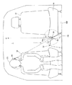
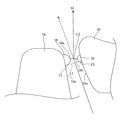
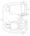
図1は、自動車の車室内において第1の実施の形態に係る車室内騒音伝播防止構造が適用された状態を示す説明図であり、図2は、図1において破線の円で示した車室内騒音伝播防止構造の要部拡大図である。
(First embodiment)
FIG. 1 is an explanatory view showing a state in which the vehicle interior noise propagation preventing structure according to the first embodiment is applied to the interior of an automobile, and FIG. 2 is a vehicle interior shown by a broken circle in FIG. It is a principal part enlarged view of the noise propagation prevention structure.
本実施の形態に係る車室内騒音伝播防止構造2は、車両の急発進又は加速時において図示しない路面とタイヤの摩擦などにより生じる透過騒音S1が乗車者O1の耳E1に伝播することを防止するものである。
The vehicle interior noise
先ず、図1に示すように、車室1内には、乗車者O1が着座する運転席シート10と助手席シート12が設置されており、この運転席シート10と助手席シート12の間の位置のフロアパネル100上にセンターコンソール14が配置されている。ここで、本実施の形態では、助手席シート12の助手席座部16とセンターコンソール14が対向する車室構成部材として想定される。
First, as shown in FIG. 1, a driver's
そして、助手席シート12の助手席座部16のコンソール側側面16aとセンターコンソール14の助手席側側面14aの間の間隔は、上方に向かうにつれて漸次狭窄する構成となっている。従って、助手席側側面14aの上部位置T1と、コンソール側側面16aの上部位置T2を結ぶ線分L1の部分が、本来、助手席座部16とセンターコンソール14の間の最小対向距離を構成するものである。
And the space | interval between the
これに対して、本実施の形態においては、助手席座部16とセンターコンソール14の間の新最小対向距離構成部として、センターコンソール14の助手席側側面14aに第1突起18が設けられており、助手席座部16のコンソール側側面16aに第2突起20が設けられている。
On the other hand, in the present embodiment, the
この第1突起18及び第2突起20は、当該第1突起18の第1突起先端18aと第2突起20の第2突起先端20aとの間の距離(すなわち、図の線分L2の長さ)が、線分L1の長さ(すなわち、これら突起18及び20が無い場合における助手席座部16とセンターコンソール14の間の最小対向距離)よりも短くなり、且つこれら突起18及び20のそれぞれの第1突起先端18a、20aを結ぶ線分L2に直交する方向上に乗車者O1の耳E1が存在しないように、これら突起18、20の形状、高さ、及び配置位置が調整されている。
The
フロアパネル100を介し乗車者O1の耳E1に届く透過騒音S1は、本来であれば、助手席座部16とセンターコンソール14間の最小対向距離を表す線分L1に直交する方向、より詳細には、線分L1を含む平面に直交する方向に沿って進行する(図1及び2の破線矢印を参照)。
The transmitted noise S1 that reaches the ear E1 of the passenger O1 via the
しかし、上記構成によれば、助手席座部16とセンターコンソール14の間の新最小対向距離構成部として構成した第1突起18及び第2突起20により、線分L2の部分が新最小対向距部分として変更されることとなる。従って、上記透過騒音S1の進行方向は、この線分L2の方向に直交する方向、より詳細には線分L2を含む平面に直交する方向(図1及び2の実線矢印の方向)に変更されることとなる。そして、進行方向が変更された後の透過騒音S1は、乗車者O1の耳E1に向かう方向から逸れているので、透過騒音S1が乗車者O1の耳に届くことにより当該乗車者O1に不快性を与えることを防止することができる。
However, according to the above configuration, the portion of the line segment L2 is made the new minimum counter distance by the
さらに、本実施の形態では、センターコンソール14の助手席側側面14aと助手席座部16のコンソール側側面16aにそれぞれ第1突起部18及び第2突起部20を設けるという極めて簡易な構成で、これらの間の最小対向距離部分を新たに構成して、透過騒音S1の進行方向を逸らすことが可能であることが注目すべき点である。
Furthermore, in the present embodiment, the
また、第1突起部18及び第2突起部20の助手席側側面14a又はコンソール側側面16a上における配置位置の変更や、突起の形状を変更することにより、上記最小対向距離部分を調整して、乗車者O1の耳E1に透過騒音が伝達されない範囲で任意に当該透過騒音S1の進行方向を調節することも可能である。
Further, by adjusting the arrangement position of the
なお、第1突起18及び第2突起20は、それぞれ、助手席座部16のコンソール側側面16a及びセンターコンソール14の助手席側側面14aに対して一体成形されていても良いし、別体に構成されて所望の手段で接着結合するようにしても良い。
The
また、第1突起18及び第2突起20は、助手席座部16のコンソール側側面16a及びセンターコンソール14の助手席側側面14aの車体前後方向の延在方向全域に亘って伸長する形状であっても良いし、当該車体前後方向の延在方向の一部に亘る形状であっても良い。すなわち、乗車者O1の耳E1に向かって進行する透過騒音S1の方向を変更する機能を果たす形状であれば、当業者が想定し得る範囲の種々の形状をとることができる。
Further, the
(第2の実施の形態)
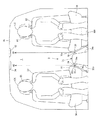
図3は、第2の実施の形態に係る車室内騒音伝播防止構造2の説明図である。なお、第1の実施の形態と同様の要素には同一の符号を付し、その説明を省略する。本実施の形態では、新最小対向距離構成部として、運転席10の運転席座部30におけるセンターコンソール14側のコンソール側側面30aにも第3突起部22が設けられており、センターコンソール14の運転席座部30側の側面14においても第4突起部24が設けられている。この第3突起部22及び第4突起部24は、上記第1突起18及び第2突起20と同様に、路面等から生じてフロアパネル100を介し助手席の乗車者O2の耳E2に直進する透過騒音S2を、当該乗車者O2の耳E2からずらすことができる態様で設けられている。すなわち、第3突起部22及び第4突起部24は、第1突起18及び第2突起20とセンターコンソール14を中心としたほぼ鏡像関係となる形状及び配置態様で設けられている。
(Second Embodiment)
FIG. 3 is an explanatory diagram of the vehicle interior noise
従って、本実施の形態に係る車室内騒音伝播防止構造2では、フロアパネル100から乗車者O1の耳に届く透過騒音S1を当該乗車者O1の耳から逸らすだけでなく、同様の原理でフロアパネル100から助手席12の乗車者O2の耳に届く透過騒音S2も当該乗車者O2の耳から逸らすことができる。
Therefore, in the vehicle interior noise
さらに、本実施の形態では、上述の進行方向が変更された透過騒音S1及び透過騒音S2をそれぞれ吸収する吸音材32、34が車室天井面36に設けられている。具体的に、吸音材32は、第1突起18の第1突起先端18a及び第2突起22の先端22aを結ぶ線分L2に直交する方向に進行する透過騒音S1の進行方向延長線上に位置するように車室天井面36に配置されており、吸音材34は、第3突起部22の先端22a及び第4突起部24の第4突起先端24aを結ぶ線分L3に直交する方向に進行する透過騒音S2の進行方向延長線上に位置するように車室天井面36に配置されている。
Further, in the present embodiment,
この吸音材32、34は、例えば、グラスウール、粗毛フェルト、化繊系材料、ウレタン系材料、ウール系材料、又は任意の孔質材料等の所望の吸音特性を有する種々の材料で形成することができ、車室天井面36形状等に合わせて所望の形状で形成することができる。また、吸音材32、34の車室天井面36への結合方法は、当業者により採用し得る任意の方法を用いることができる。
The
上述のように、吸音材32及び34をそれぞれ透過騒音S1及びS2の進行方向延長線上にある車室天井面36に設けたことにより、乗車者O1の耳及び乗車者O2の耳から逸らされた透過騒音S1及びS2は、それぞれの吸音材32及び34により吸音されることとなる。
As described above, by providing the
従って、乗車者O1や乗車者O2の耳から逸らされた透過騒音S1及びS2が、車室内の車室天井面36内面等に反射して再び乗車者O1及び乗車者O2に伝達されることを防止することができる。
Therefore, the transmitted noises S1 and S2 deviated from the ears of the passenger O1 and the passenger O2 are reflected on the inner surface of the vehicle
特に、車室内の車室天井面36等で反射される透過騒音S1及びS2に対して何ら対策を講じないと、当該反射後の透過騒音S1及びS2が、車室内においてさらに反射や回折等されることにより、他の音源から発せられる音波と干渉して強めあい透過騒音の音圧レベルが高まる可能性が考えられるが、本実施の形態に係る構成によりこの事象を防止して、乗車者O1及びO2の快適性をより良好なものとすることができる。
In particular, if no measures are taken against the transmitted noise S1 and S2 reflected by the vehicle
(第3の実施の形態)
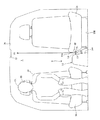
図4に示すように、本実施の形態に係る車室内騒音伝播防止構造2では、車室構成部材間の新最小対向距離構成部として、第1実施の形態や第2実施の形態に係る突起18a等に代えて、助手席座部16のコンソール側側面16aに切欠き状の凹み部40を設けている。
(Third embodiment)
As shown in FIG. 4, in the vehicle interior noise
本実施の形態では、この凹み部40を設けたことにより、センターコンソール14の助手席側側面14aと助手席座部16のコンソール側側面16aとの間で定まる最小対向距離の部分が、本来の線分L4の部分からずれて、コンソール側側面16aの点T3と凹み部40の縁部T4を結んだ線分L5の部分となる。従って、透過騒音S1は、この線分L5に直交する方向に進行され、吸音材32に吸収されることとなる。
In the present embodiment, by providing the
本実施の形態に係る車室内騒音伝播防止構造2によれば、本来、センターコンソール14の助手席側側面14aと助手席座部16のコンソール側側面16aにおいて定まる最小対向距離を形成していた部分である線分L4が、コンソール側側面16aに凹み部40が形成されたことで、本来の位置から線分L5の部分にずれて、結果として透過騒音S1が進行する方向が変更されることとなる。すなわち、コンソール側側面16aに凹み部40を設けるという極めて簡易な構成で、透過騒音S1の進行方向を乗車者O1の耳E1から逸らすという効果を得ることができる。特に、凹み部40の配置位置、形状、深さ、幅、及び車体前後方向への延在長さ等を変更することにより、上記最小対向距離部分を調整して乗車者O1の耳E1に透過騒音が伝達されない範囲で任意に当該透過騒音S1の進行方向を調節することが可能である。
According to the vehicle interior noise
(第4の実施の形態)
図5に示すように、本実施の形態に係る車室内騒音伝播防止構造2では、第1実施の形態と同様に車室構成部材間の新最小対向距離構成部として第1突起18及び第2突起20が採用されており、さらに、本実施の形態に係る特有の構成として、助手席座部16のコンソール側側面16aに透過騒音吸収部42が形成されている。この透過騒音吸収部42は、助手席座部16の切欠き状部分を多孔質材料等の任意の高吸音特性を有する材料で構成したものである。
(Fourth embodiment)
As shown in FIG. 5, in the vehicle interior noise
そして、本実施の形態では、特に第1突起部18の第1突起先端18a及び第2突起20の第2突起先端20aを結ぶ線分L6に対して直交する方向の延長線上に、透過騒音吸収部42が位置するように調節されている。特に、この調節は、図から明らかなように、第1突起部18と第2突起部20の配置高さ位置をずらすことで実現している。すなわち、第1突起部18を第2突起部20よりも高い位置に設けることで、線分L6が水平から一定角度傾いて図上右下がりの状態となるので、これに直交する方向は図上右上がりの方向となって、その延長線上に透過騒音吸収部42が存在することとなる。
In the present embodiment, the transmitted noise is absorbed particularly on the extended line in the direction perpendicular to the line segment L6 connecting the
上記構成によれば、線分L6に直交する方向に進行する透過騒音S1は、透過騒音吸収部42の部分で吸音されることとなる。従って、本来、乗車者O1の耳E1に伝播されるはずであった透過騒音S1の進行方向をずらして、乗車者O1の耳E1に伝播されないようにしつつ、当該透過騒音S1を車室1内における比較的下方の透過騒音吸収部42にて吸音することができる。これにより、進行方向が変更された透過騒音S1の車室1内における進行距離を極力短くすることができるので、当該進行方向変更後の透過騒音S1が、他の音源から発せられて車室内で進行する他の音と干渉して強めあう等の現象をより好適に防止することができ、結果としてさらなる車室内の透過騒音の低減に資することとなる。
According to the above configuration, the transmitted noise S1 traveling in the direction orthogonal to the line segment L6 is absorbed by the transmitted
(第5実施の形態)
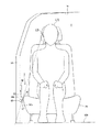
本実施の形態では、図6に示すように、対向する車室構成部材として運転席座部16とBピラー44を採用した場合における車室内騒音伝播防止構造2について説明する。
(Fifth embodiment)
In the present embodiment, as shown in FIG. 6, the vehicle interior noise
具体的に、本実施の形態に係る車室内騒音伝播防止構造2は、フロアパネル100やBピラー44の下方部分を透過して、運転席座部30におけるBピラー側側面30bとBピラー44の内面44aとの間を進行し、乗車者O1の耳E1に伝達される透過騒音S3を逸らすものである。
Specifically, the vehicle interior noise
本構造2では、運転席座部30におけるBピラー側側面30bに第5突起部46が設けられており、Bピラー44の内周面44aに第6突起部48が設けられている。そして、本実施の形態では、第6突起部48が、第5突起部46に対してほぼ突起幅一個分低い位置に設けられている。この突起配置により、第5突起部46と第6突起部48とを結ぶ新たな最小対向距離線分である線分L7は、水平方向に対してBピラー44の内周面44a側に傾いて図上左上がりの線分となる。従って、この線分L7に直交する透過騒音S3の変更された進行方向は、Bピラー44の内面44aに向かうこととなり、乗車者O1の耳E1から逸れることとなる。
In the
さらに、本実施の形態でも、線分L7に直交する透過騒音S3の進行方向上におけるBピラー内面44aに吸音材50を設けることで、当該透過騒音S3がBピラー内面44aで反射してしまうことを防止することができる。
Furthermore, also in this embodiment, by providing the
なお、本発明は、上記実施の形態に限定されるものではなく、発明の要旨の範囲内で種々の変更が可能である。例えば、上記形態においては、対向する車室構成部材が、助手席座部16や運転席座部30とセンターコンソール14、及び運転席座部30とBピラー44の場合について説明したが、これに限られるものではなく、ドアとシート、又はシートとトンネル等の他の車室構成部材において本発明の車室内騒音伝播防止構造を適用するようにしても良い。
In addition, this invention is not limited to the said embodiment, A various change is possible within the range of the summary of invention. For example, in the above embodiment, the description has been given of the case where the opposite passenger compartment components are the
また、上記実施の形態では、最小距離変更部として突起部や凹み部を採用しているが、これに限られるものではなく、対向する車室構成部材の最小対向距離を変更し、且つ変更後の最小対向距離部分を結ぶ線分に直交する方向を、上記乗車者O1、O2の耳に進行する方向からずらすことができるものであれば任意の構造を採用することが可能である。 Further, in the above-described embodiment, the protrusions and the dents are employed as the minimum distance changing part. However, the present invention is not limited to this, and the minimum facing distance of the facing vehicle compartment components is changed and after the change. Any structure can be adopted as long as the direction orthogonal to the line segment connecting the minimum facing distance portions can be shifted from the direction of traveling to the ears of the passengers O1 and O2.
また、上記各実施の形態では、新最小対向距離構成部としてセンターコンソール14の助手席側側面14aと助手席座部のコンソール側側面16aの双方にそれぞれ、第1突起18及び第2突起20を設けて、これらの第1突起先端18a及び第2突起先端20の間の距離を最小対向距離とすることで、透過騒音S1の進行方向を変更しているが、これに限られず、例えば、第1突起18のみを設けて第2突起20を設けず、第1突起18の先端18aと助手席座部のコンソール側側面16aとの間の距離を最小対向距離とすることで、透過騒音S1の進行方向を変更しても良い。
Further, in each of the above-described embodiments, the
1 車室
2 車室内騒音伝播防止構造
10 運転席シート(車室構成部材、シート)
12 助手席シート(車室構成部材、シート)
14 センターコンソール(車室構成部材)
14a 助手席側側面(相互対向面)
16 助手席座部(シートの座部)
16a コンソール側側面(対向面)
18 第1突起部(新最小対向距離構成部)
18a 第1突起先端
20 第2突起部(新最小対向距離構成部)
20a 第2突起先端
22 第3突起部(新最小対向距離構成部)
22a 第3突起先端
24 第4突起部(新最小対向距離構成部)
24a 第4突起先端
30 運転席座部(シートの座部)
30a コンソール側側面
30b Bピラー側側面(相互対向面)
32 吸音材(吸音手段)
34 吸音材(吸音手段)
40 凹み部(新最小対向距離構成部)
42 透過騒音吸収部(吸音手段)
44 Bピラー(車室構成部材)
44a Bピラー内面(相互対向面)
46 第5突起部(新最小対向距離構成部)
46a 第5突起先端
48 第6突起部(新最小対向距離構成部)
48a 第6突起先端
50 吸音材(吸音手段)
100 フロアパネル
S1、S2、S3 透過騒音
O1、O2 乗車者
E1、E2 乗車者の耳
1
12 Passenger seat (chamber component, seat)
14 Center console (vehicle compartment components)
14a Front passenger seat side (mutual facing surface)
16 Passenger seat (seat seat)
16a Console side surface (opposite surface)
18 First protrusion (new minimum facing distance component)
18a
20a
22a
24a
30a
32 Sound absorbing material (sound absorbing means)
34 Sound absorbing material (sound absorbing means)
40 dent (new minimum facing distance component)
42 Transmission noise absorber (sound absorbing means)
44 B-pillar (vehicle compartment component)
44a B pillar inner surface (mutual facing surface)
46 5th protrusion (new minimum facing distance component)
46a 5th protrusion tip 48 6th protrusion part (new minimum opposing distance constituent part)
48a
100 Floor panel S1, S2, S3 Transmission noise O1, O2 Passenger E1, E2 Passenger's ear
Claims (7)
上記透過騒音を上記乗車者の耳に進行する方向から逸らすように、新たな上記最小対向距離部分を構成する新最小対向距離構成部を設けたことを特徴とする車室内騒音伝播防止構造。 Transmitted noise transmitted through the floor panel of an automobile and propagating to the passenger's ear by traveling in the direction perpendicular to the line segment connecting the minimum facing distance portions of the compartment constituent members between the opposing compartment constituent members. A structure for preventing noise propagation in the passenger compartment,
A vehicle interior noise propagation preventing structure comprising a new minimum facing distance component that constitutes the new minimum facing distance portion so as to divert the transmitted noise from the direction of traveling to the ear of the passenger.
上記対向する車室構成部材の相互対向面の少なくとも一方に設けられた突起部である請求項1に記載の車室内騒音伝播防止構造。 The new minimum facing distance component is
The vehicle interior noise propagation preventing structure according to claim 1, wherein the vehicle interior noise propagation preventing structure is a protrusion provided on at least one of the mutually facing surfaces of the opposing vehicle interior constituent members.
上記対向する車室構成部材の相互対向面の少なくとも一方に設けられた凹み部である請求項1に記載の車室透過騒音伝播防止構造。 The new minimum facing distance component is
The vehicle interior transmitted noise propagation preventing structure according to claim 1, wherein the vehicle interior transmitted noise propagation preventing structure is a recessed portion provided on at least one of mutually facing surfaces of the facing vehicle compartment constituting members.
Priority Applications (1)
| Application Number | Priority Date | Filing Date | Title |
|---|---|---|---|
| JP2013267735A JP6242210B2 (en) | 2013-12-25 | 2013-12-25 | Vehicle interior noise propagation prevention structure |
Applications Claiming Priority (1)
| Application Number | Priority Date | Filing Date | Title |
|---|---|---|---|
| JP2013267735A JP6242210B2 (en) | 2013-12-25 | 2013-12-25 | Vehicle interior noise propagation prevention structure |
Publications (2)
| Publication Number | Publication Date |
|---|---|
| JP2015123783A true JP2015123783A (en) | 2015-07-06 |
| JP6242210B2 JP6242210B2 (en) | 2017-12-06 |
Family
ID=53534835
Family Applications (1)
| Application Number | Title | Priority Date | Filing Date |
|---|---|---|---|
| JP2013267735A Active JP6242210B2 (en) | 2013-12-25 | 2013-12-25 | Vehicle interior noise propagation prevention structure |
Country Status (1)
| Country | Link |
|---|---|
| JP (1) | JP6242210B2 (en) |
Families Citing this family (1)
| Publication number | Priority date | Publication date | Assignee | Title |
|---|---|---|---|---|
| US9903952B2 (en) | 2015-03-18 | 2018-02-27 | Amazon Technologies, Inc. | GPS error correction via network of fixed point ground stations |
Citations (3)
| Publication number | Priority date | Publication date | Assignee | Title |
|---|---|---|---|---|
| JPS6220921U (en) * | 1985-07-23 | 1987-02-07 | ||
| JP2006160177A (en) * | 2004-12-10 | 2006-06-22 | Hayashi Engineering Inc | Sound absorbing structure of automobile running on road |
| JP2010076499A (en) * | 2008-09-24 | 2010-04-08 | Mazda Motor Corp | Sound absorbing structure of vehicle |
-
2013
- 2013-12-25 JP JP2013267735A patent/JP6242210B2/en active Active
Patent Citations (3)
| Publication number | Priority date | Publication date | Assignee | Title |
|---|---|---|---|---|
| JPS6220921U (en) * | 1985-07-23 | 1987-02-07 | ||
| JP2006160177A (en) * | 2004-12-10 | 2006-06-22 | Hayashi Engineering Inc | Sound absorbing structure of automobile running on road |
| JP2010076499A (en) * | 2008-09-24 | 2010-04-08 | Mazda Motor Corp | Sound absorbing structure of vehicle |
Also Published As
| Publication number | Publication date |
|---|---|
| JP6242210B2 (en) | 2017-12-06 |
Similar Documents
| Publication | Publication Date | Title |
|---|---|---|
| JP6133796B2 (en) | Soundproof body and automotive insulator | |
| JP5821424B2 (en) | Vehicle body structure | |
| CN103260954B (en) | Noise-absorbing sheet for automobile, method for manufacturing same, and baffle-muffler pad for automobile | |
| JP6245292B2 (en) | Sound insulation structure of automobile | |
| JP2015151105A (en) | Body panel structure | |
| JP4635847B2 (en) | Soundproof material | |
| KR101688281B1 (en) | Composite assembly for a motor vehicle | |
| JP6082709B2 (en) | Floor support structure for moving objects | |
| JP6242210B2 (en) | Vehicle interior noise propagation prevention structure | |
| JP5870829B2 (en) | Vehicle floor structure | |
| JP2010234896A (en) | Laying interior material for vehicle and vehicle floor structure | |
| JP2019142373A (en) | vehicle | |
| KR101047522B1 (en) | Rail vehicle with sound absorption structure | |
| JP2016060456A (en) | Vehicle cowl structure | |
| JP2007112390A (en) | Sound absorbing material for vehicles | |
| JP2023150802A (en) | Vehicle body rear part structure | |
| JP2015209018A (en) | Soundproof structure of automobile | |
| JP6889636B2 (en) | Railroad vehicle | |
| JP2015193343A (en) | Anti-vibration structure for automotive back panel | |
| KR102005144B1 (en) | Damping vibration element for vehicle roof sheet and vehicle roof sheet with damping vibration element | |
| WO2018016122A1 (en) | Sound insulation body for vehicle and silencer for vehicle | |
| EP3738826B1 (en) | Acoustically insulable seat for a public transport vehicle | |
| CN112638717A (en) | Sound-absorbing material for vehicle | |
| JP2017165168A (en) | Railway vehicle | |
| JP6420963B2 (en) | Vehicle noise reduction structure |
Legal Events
| Date | Code | Title | Description |
|---|---|---|---|
| A621 | Written request for application examination |
Free format text: JAPANESE INTERMEDIATE CODE: A621 Effective date: 20160915 |
|
| A977 | Report on retrieval |
Free format text: JAPANESE INTERMEDIATE CODE: A971007 Effective date: 20170608 |
|
| A131 | Notification of reasons for refusal |
Free format text: JAPANESE INTERMEDIATE CODE: A131 Effective date: 20170627 |
|
| A521 | Request for written amendment filed |
Free format text: JAPANESE INTERMEDIATE CODE: A523 Effective date: 20170824 |
|
| TRDD | Decision of grant or rejection written | ||
| A01 | Written decision to grant a patent or to grant a registration (utility model) |
Free format text: JAPANESE INTERMEDIATE CODE: A01 Effective date: 20171010 |
|
| A61 | First payment of annual fees (during grant procedure) |
Free format text: JAPANESE INTERMEDIATE CODE: A61 Effective date: 20171107 |
|
| R150 | Certificate of patent or registration of utility model |
Ref document number: 6242210 Country of ref document: JP Free format text: JAPANESE INTERMEDIATE CODE: R150 |
|
| R250 | Receipt of annual fees |
Free format text: JAPANESE INTERMEDIATE CODE: R250 |
|
| R250 | Receipt of annual fees |
Free format text: JAPANESE INTERMEDIATE CODE: R250 |
|
| R250 | Receipt of annual fees |
Free format text: JAPANESE INTERMEDIATE CODE: R250 |
|
| R250 | Receipt of annual fees |
Free format text: JAPANESE INTERMEDIATE CODE: R250 |
|
| R250 | Receipt of annual fees |
Free format text: JAPANESE INTERMEDIATE CODE: R250 |
|
| R250 | Receipt of annual fees |
Free format text: JAPANESE INTERMEDIATE CODE: R250 |