JP2015123786A - Front structure in motor cycle - Google Patents
Front structure in motor cycle Download PDFInfo
- Publication number
- JP2015123786A JP2015123786A JP2013267791A JP2013267791A JP2015123786A JP 2015123786 A JP2015123786 A JP 2015123786A JP 2013267791 A JP2013267791 A JP 2013267791A JP 2013267791 A JP2013267791 A JP 2013267791A JP 2015123786 A JP2015123786 A JP 2015123786A
- Authority
- JP
- Japan
- Prior art keywords
- headlight
- front cover
- lens
- disposed
- housing
- Prior art date
- Legal status (The legal status is an assumption and is not a legal conclusion. Google has not performed a legal analysis and makes no representation as to the accuracy of the status listed.)
- Granted
Links
Images
Classifications
-
- B—PERFORMING OPERATIONS; TRANSPORTING
- B62—LAND VEHICLES FOR TRAVELLING OTHERWISE THAN ON RAILS
- B62J—CYCLE SADDLES OR SEATS; AUXILIARY DEVICES OR ACCESSORIES SPECIALLY ADAPTED TO CYCLES AND NOT OTHERWISE PROVIDED FOR, e.g. ARTICLE CARRIERS OR CYCLE PROTECTORS
- B62J6/00—Arrangement of optical signalling or lighting devices on cycles; Mounting or supporting thereof; Circuits therefor
- B62J6/02—Headlights
Landscapes
- Engineering & Computer Science (AREA)
- Mechanical Engineering (AREA)
- Non-Portable Lighting Devices Or Systems Thereof (AREA)
- Lighting Device Outwards From Vehicle And Optical Signal (AREA)
Abstract
【課題】車体フレームがその前端部に有するヘッドパイプの前方に配置されるフロントカバーと、ヘッドパイプの前方に配置されるヘッドライトとを備える自動二輪車において、フロントカバーを上下に分割して小型化を図った上でヘッドライトのレンズが可及的に大きく見える構造とし、独特な外観形状が得られるようにする。
【解決手段】フロントカバー15が、上部フロントカバー16および下部フロントカバー17から成り、ヘッドライトハウジング30と、該ヘッドライトハウジング30を前方から覆うレンズとを有するヘッドライト25が、上部フロントカバー16および下部フロントカバー17を連結するように設けられる。
【選択図】 図3In a motorcycle having a front cover disposed in front of a head pipe at a front end of a body frame and a headlight disposed in front of the head pipe, the front cover is divided into upper and lower parts to reduce the size. The lens of the headlight is made to look as large as possible, so that a unique appearance can be obtained.
A front cover 15 includes an upper front cover 16 and a lower front cover 17, and a headlight 25 having a headlight housing 30 and a lens that covers the headlight housing 30 from the front includes the upper front cover 16 and the headlight housing 30. A lower front cover 17 is provided to be connected.
[Selection] Figure 3
Description
本発明は、車体フレームがその前端部に有するヘッドパイプの前方に配置されるフロントカバーと、前記ヘッドパイプの前方に配置されるヘッドライトとを備える自動二輪車に関し、特にその前部構造の改良に関する。 The present invention relates to a motorcycle including a front cover that is disposed in front of a head pipe that a vehicle body frame has at a front end portion thereof, and a headlight that is disposed in front of the head pipe. .
このような自動二輪車は、たとえば特許文献1で知られており、このものでは、灯火器のバルブを支持するベース部材全体が、フロントカバーで覆われる構成となっている。 Such a motorcycle is known, for example, from Patent Document 1, and in this case, the entire base member that supports the bulb of the lamp is covered with a front cover.
上記特許文献1で開示されるものでは、灯火器のレンズの周囲を連続して一体に覆うようにフロントカバーを形成する必要があり、フロントカバーが大型化している。そこでフロントカバーの小型化を図るために、フロントカバーを上部フロントカバーおよび下部フロントカバーとで上下に分割し、上部フロントカバーおよび下部フロントカバー間に灯火器であるヘッドライトを配置することが考えられるが、その際、ヘッドライトの視認性を高めるために、ヘッドライトのレンズが可及的に大きく見える構造とすることが望まれる。 In what is disclosed in Patent Document 1, it is necessary to form the front cover so as to continuously and integrally cover the periphery of the lens of the lamp, and the front cover is enlarged. Therefore, in order to reduce the size of the front cover, it is conceivable to divide the front cover into upper and lower front covers and a headlight as a lighting device between the upper front cover and the lower front cover. However, in this case, in order to improve the visibility of the headlight, it is desired to have a structure in which the lens of the headlight looks as large as possible.
本発明は、かかる事情に鑑みてなされたものであり、フロントカバーを上下に分割して小型化を図った上でヘッドライトのレンズが可及的に大きく見える構造とし、独特な外観形状が得られるようにした自動二輪車における前部構造を提供することを目的とする。 The present invention has been made in view of such circumstances, and has a structure in which the lens of the headlight looks as large as possible after the front cover is divided into upper and lower parts, and a unique appearance shape is obtained. An object of the present invention is to provide a front structure in a motorcycle.
上記目的を達成するために、本発明は、車体フレームがその前端部に有するヘッドパイプの前方に配置されるフロントカバーと、前記ヘッドパイプの前方に配置されるヘッドライトとを備える自動二輪車において、前記フロントカバーが、上部フロントカバーおよび下部フロントカバーから成り、ヘッドライトハウジングと、該ヘッドライトハウジングを前方から覆うレンズとを有する前記ヘッドライトが、前記上部フロントカバーおよび前記下部フロントカバーを連結するように設けられることを第1の特徴とする。 In order to achieve the above object, the present invention provides a motorcycle including a front cover disposed in front of a head pipe that a vehicle body frame has at a front end thereof, and a headlight disposed in front of the head pipe. The front cover includes an upper front cover and a lower front cover, and the headlight having a headlight housing and a lens that covers the headlight housing from the front connects the upper front cover and the lower front cover. It is a first feature that it is provided.
また本発明は、第1の特徴の構成に加えて、前記ヘッドライトハウジングの両側後部が、前記レンズの後縁に連続しつつ外部に露出する露出面を形成するようにして、前記上部フロントカバーおよび前記下部フロントカバーの両側後端部間に配置されることを第2の特徴とする。 According to the present invention, in addition to the configuration of the first feature, the rear portions on both sides of the headlight housing form an exposed surface that is exposed to the outside while continuing to the rear edge of the lens. The second feature is that the lower front cover is disposed between the rear end portions on both sides.
本発明は、第2の特徴の構成に加えて、前記露出面の後縁が、側面視で前記上部フロントカバーおよび前記下部フロントカバーの両側後縁に滑らかに連なるように配置されることを第3の特徴とする。 According to the present invention, in addition to the configuration of the second feature, the rear edge of the exposed surface is arranged so as to be smoothly connected to both side rear edges of the upper front cover and the lower front cover in a side view. Three features.
本発明は、第1〜第3の特徴の構成のいずれかに加えて、前記レンズの後縁の最後端が、側面視で前記ヘッドパイプよりも後方に配置されることを第4の特徴とする。 According to a fourth feature of the present invention, in addition to any one of the first to third features, a rear end of the rear edge of the lens is disposed behind the head pipe in a side view. To do.
さらに本発明は、第1〜第4の特徴の構成のいずれかに加えて、前記ヘッドライトは、前記ヘッドライトハウジングおよび前記レンズに加えて、前記ヘッドライトハウジングの中央部に支持されるヘッドライトバルブと、そのヘッドライトバルブの左右両側に配置されて前記ヘッドライトハウジングに支持される一対のポジションライトバルブと、それらのポジションライトバルブからの光を導くようにして前記レンズに沿って延びる一対の導光部材とを備えることを第5の特徴とする。 In addition to any one of the first to fourth features of the present invention, the headlight is supported by a central portion of the headlight housing in addition to the headlight housing and the lens. A pair of position light bulbs disposed on the left and right sides of the headlight bulb and supported by the headlight housing, and a pair extending along the lens so as to guide light from the position light bulbs A fifth feature is that a light guide member is provided.
本発明の第1の特徴によれば、上部フロントカバーおよび下部フロントカバーから成るようにフロントカバーを構成してフロントカバーの小型化を図った上で、上部フロントカバーおよび下部フロントカバーをヘッドライトで連結するようにして、上部フロントカバーおよび下部フロントカバーと、ヘッドライトとでそれぞれ形成される線分を強調するようにした独特な外観形状とすることができ、ヘッドライトを強調してヘッドライトの視認性を高めることができる。 According to the first aspect of the present invention, the front cover is configured to include the upper front cover and the lower front cover to reduce the size of the front cover, and then the upper front cover and the lower front cover are connected with the headlight. By connecting, it can have a unique appearance shape that emphasizes the line segments formed by the upper front cover and lower front cover and the headlight, respectively, Visibility can be improved.
また本発明の第2の特徴によれば、ヘッドライトハウジングの両側後部が形成する露出面が、レンズの後縁に連続しつつ外部に露出して上部フロントカバーおよび下部フロントカバーの両側後端部間に配置されるので、ヘッドライトがより強調されることになり、ヘッドライトの視認性をさらに高めることができる。 According to the second aspect of the present invention, the exposed surfaces formed by the rear portions on both sides of the headlight housing are exposed to the outside while continuing to the rear edge of the lens, so that the rear end portions on both sides of the upper front cover and the lower front cover. Since it is disposed between the headlights, the headlight is more emphasized, and the visibility of the headlight can be further enhanced.
本発明の第3の特徴によれば、露出面の後縁が側面視で上部フロントカバーおよび下部フロントカバーの両側後縁に滑らかに連なるので、フロントカバーの後縁の一部をヘッドライトハウジングで形成するようにしてヘッドライトを車幅方向に可及的に大きくすることができ、ヘッドライトの視認性がさらに向上する。 According to the third feature of the present invention, since the rear edge of the exposed surface is smoothly connected to the rear edge on both sides of the upper front cover and the lower front cover in a side view, a part of the rear edge of the front cover is formed by the headlight housing. Thus, the headlight can be made as large as possible in the vehicle width direction, and the visibility of the headlight is further improved.
本発明の第4の特徴によれば、レンズの後縁の最後端が側面視でヘッドパイプよりも後方に在ることで、ヘッドライトを前後方向で大きく設けることができ、側方からのヘッドライトの視認性を高めることができる。 According to the fourth aspect of the present invention, the rear end of the rear edge of the lens is located behind the head pipe in a side view, so that the headlight can be provided larger in the front-rear direction, and the head from the side can be provided. The visibility of the light can be increased.
さらに本発明の第5の特徴によれば、ヘッドライトバルブの左右両側に配置される一対のポジションライトバルからの光が、レンズに沿って延びる導光部材で導かれるので、ヘッドライトの発光面積をより大きくすることができ、これによってもヘッドライトの視認性が向上する。 Furthermore, according to the fifth feature of the present invention, the light from the pair of position light valves disposed on the left and right sides of the headlight bulb is guided by the light guide member extending along the lens. Can be made larger, and this also improves the visibility of the headlight.
本発明の実施の形態について添付の図面を参照しながら説明する。なお以下の説明で前後、上下および左右は自動二輪車に乗車した乗員から見た方向を言うものとする。 Embodiments of the present invention will be described with reference to the accompanying drawings. In the following description, front and rear, top and bottom, and left and right refer to directions viewed from a passenger riding a motorcycle.
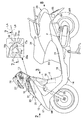
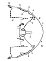
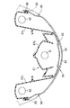
先ず図1において、この自動二輪車は、スクータ型の自動二輪車であり、その車体フレームFが前端部に備えるヘッドパイプ11には、前輪WFを軸支するフロントフォーク12および操向ハンドル13が操向可能に支承される。また前記車体フレームFには、後輪ERを駆動する動力を発揮するユニットスイング式のパワーユニットPが揺動可能に支承されており、このパワーユニットPの後部に前記後輪WRが軸支される。
First, in FIG. 1, the motorcycle is a scooter type motorcycle, and a
前記パワーユニットPの一部および前記車体フレームFは、車体カバー14で覆われており、この車体カバー14は、前記ヘッドパイプ11を前方から覆うフロントカバー15と、前記ヘッドパイプ11を後方側から覆うセンターカバー18と、該センターカバー18の下部に連設されるステップフロア19と、フロントカバー15、センターカバー18およびステップフロア19の両側を連結する左右一対のレッグシールド20と、それらのレッグシールド20の下端から後方に延びるとともに前記ステップフロア19の両側に連設される左右一対のアンダーサイドカバー21と、前記ステップフロア19の後端から上方に立ち上がるアンダーフロントカバー22と、アンダーフロントカバー22の左右両側に連設される左右一対のリヤサイドカバー23とを備え、前記アンダーフロントカバー22および左右一対のリヤサイドカバー23上に、タンデム型の乗車用シート24が配設される。
A part of the power unit P and the vehicle body frame F are covered with a
前記フロントカバー15にはヘッドライト25が配設される。また前記操向ハンドル13の中央部は前後割りのハンドルカバー26で覆われており、このハンドルカバー26の左右両側にはウインカ27が配設される。さらに左右一対の前記リヤサイドカバー23の後端間にリヤコンビネーションライト28が配設される。
A
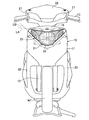
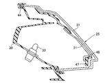
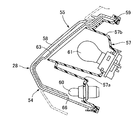
図2および図3を併せて参照して、前記フロントカバー15は、上部フロントカバー16および下部フロントカバー17から成るものであり、前記ヘッドライト25が、前記上部フロントカバー16および前記下部フロントカバー17を連結するようにして前記上部フロントカバー16および前記下部フロントカバー17間に設けられる。
2 and 3, the
前記上部フロントカバー16および前記下部フロントカバー17は、前記ヘッドライト25で相互に連結されていない状態では、車両前方からの正面視で略V字状となる開口部29が相互間に生じるように形成されるものであり、その開口部29を塞ぐように前記ヘッドライト25が配置される。
When the
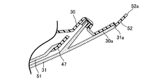
図4〜図6を併せて参照して、前記ヘッドライト25は、ヘッドライトハウジング30と、該ヘッドライトハウジング30を前方から覆うレンズ31と、前記ヘッドライトハウジング30の中央部に支持されるヘッドライトバルブ32と、そのヘッドライトバルブ32の左右両側に配置されて前記ヘッドライトハウジング30に支持される一対のポジションライトバルブ33,33とを備える。
4 to 6, the
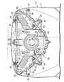
図3に注目して、前記ヘッドライトハウジング30の上部には、左右に離隔した一対の第1上部締結腕が34,34が前記開口部29の上縁部で上部フロントカバー16の裏面にねじ部材35,35でそれぞれ締結されるようにして一体に設けられるとともに、それらの第1上部締結腕34,34間の中央部に配置される第2上部締結腕部36が前記開口部29の上縁部で前記上部フロントカバー16の裏面にねじ部材37で締結されるようにして一体に設けられる。
Referring to FIG. 3, a pair of first upper fastening
また前記ヘッドライトハウジング30の下部には、左右に離隔した一対の第1下部締結腕38,38が前記開口部29の下縁部で前記下部フロントカバー17の裏面にねじ部材39,39でそれぞれ締結されるようにして一体に設けられるとともに、それらの第1下部締結腕38,38間で左右に離隔するようにして配置される一対の第2下部締結腕40,40が前記開口部29の下縁部で前記下部フロントカバー17の裏面にねじ部材41,41でそれぞれ締結されるようにして一体に設けられる。
A pair of first lower fastening
前記レンズ31は、前記フロントカバー15の開口部29に一部を臨ませるようにして前記ヘッドライトハウジング30に前方からシール部材44を介して取付けられ、このレンズ31の後縁31aの最後端31aaは、図1で明示するように、側面視で前記車体フレームFの前端部の前記ヘッドパイプ11よりも後方に配置される。すなわち側面視で前記レンズ31の後縁31aの最後端31aaを通る仮想鉛直線Lが前記ヘッドパイプ11よりも後方位置に在る。
The
前記ヘッドライトバルブ32は、前記ヘッドライトハウジング30の略中央部に支持されるものであり、このヘッドライトバルブ32からの光を前方に向けて反射するための椀状のリフレクタ45が前記ヘッドライトハウジング30内の中央部に配置される。このリフレクタ45は上下に制限された範囲で首振りすることを可能として前記ヘッドライト25に支持されており、このリフレクタ45の首振り角度を回動調整することでヘッドライトバルブ32の光軸を調整することができる。
The
また前記レンズ31の左右両側で該レンズ31の内面に沿うとともに前記リフレクタ45を臨ませる窓46を中央部に有するエクステンション47が前記ヘッドライトハウジング30内に配置され、このエクステンション47は前記ヘッドライトハウジング30に固定される。
An
前記ポジションライトバルブ33は、前記エクステンション47の左右両側部で覆われるようにして前記ヘッドライトバルブ32の左右両側に配置されて該ヘッドライトハウジング30に支持される。
The position
ところで前記エクステンション47の左右両側には、たとえば3個のスリット48,49,50が前記レンズ31の内面に沿って延びるようにしてそれぞれ設けられており、前記ポジションライトバルブ33、33からの光を前記レンズ31の左右両側部で外観することができるようにしてポジションライトバルブ33,33からの光を導く左右一対の導光部材51,51が、前記エクステンション47の左右両側部のスリット49〜50にぞれぞれ臨むように配置され、これらの導光部材51,51は前記エクステンション47に支持される。
Incidentally, for example, three
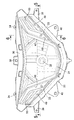
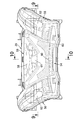
図7を併せて参照して、前記ヘッドライトハウジング30の両側後部は、前記レンズ31の後端部に内方から当接する当接面30aと、前記レンズ31の後縁に連続しつつ外部に露出する露出面52とを形成するようにして、前記上部フロントカバー16および前記下部フロントカバー17の両側後端部間に配置される。
Referring also to FIG. 7, the rear portions on both sides of the
また前記露出面52の後縁52aは、側面視で前記上部フロントカバー16および前記下部フロントカバー17の両側後縁16a,17aに滑らかに連なるように配置される。
Further, the
図8〜図10を併せて参照して、前記リヤコンビネーションライト28は、テールライト54と、該テールライト54の上方に配置されるストップライト55と、前記テールライト54の左右両側に配置されるウインカーライト56,56とを備える。
Referring also to FIGS. 8 to 10, the rear combination light 28 is disposed on the
前記リヤコンビネーションライト28は、前記左右一対の前記リヤサイドカバー23の後部に固定されるベース部材57を有しており、このベース部材57には、前記リヤサイドカバー23の後端部から後方に突出するアウターレンズ58がシール部材59を介して取付けられる。
The rear combination light 28 has a
前記アウターレンズ58内には、テールライトバルブ60と、該テールライトバルブ60の上方に配置されるストップライトバルブ61と、前記テールライトバルブ60および前記ストップライトバルブ61の左右両側に配置される左右一対のウインカバルブ62,62とが、それらのバルブ60,61,62,62に共通な前記アウターレンズ58で覆われるようにして配置される。
In the
前記テールライト54は、前記ベース部材57に形成されるテールライト用ハウジング部57aに支持される前記テールライトバルブ60と、前記アウターレンズ58と、該アウターレンズ58の内方に配置されて前記テールライトバルブ60を覆うインナーレンズ63とで構成される。前記テールライト用ハウジング部57aは車両前後方向の後方から見た正面視では略V字状をなすように配置されており、前記テールライトバルブ60は前記V字の頂点部に対応する位置で前記テールライト用ハウジング部57aに支持される。また前記インナレンズ31は赤色に着色されている。
The
前記ストップライト55は、前記テールライトライト用ハウジング部57aの上方で前記ベース部材57に形成されるストップライト用ハウジング部57bに支持される前記ストップライトバルブ61と、そのストップライトバルブ61を覆う前記インナーレンズ63および前記アウターレンズ58とで構成され、前記ストップライトバルブ61は、前記テールライト54の左右両側上部間に配置されるようにして前記ストップライト用ハウジング部57bに支持される。
The
前記ウインカライト58は、前記ベース部材57の左右両側に形成されるウインカ用ハウジング部57cに支持される前記ウインカバルブ62と、そのウインカバルブ62を覆う前記アウターレンズ58と、前記ウインカ用ハウジング部57cの下部だけを覆う前記インナーレンズ63とで構成される。
The
ところで前記リヤコンビネーションライト28の下方には、図1で示すように、前記後輪WRを斜め後ろ上方から覆うリヤフェンダ64に取付けられるライセンスプレート65が配置されており、前記テールライト54における前記テールライトバルブ60の下方で前記インナーレンズ63には、前記ライセンスプレート65側に向けて前記テールライトバルブ60からの光を導く透光66が設けられる。すなわち前記リヤコンビネーションライト28は、前記ライセンスプレート65を照らすライセンスライトの機能も果たすことになる。
By the way, as shown in FIG. 1, a
次にこの実施の形態の作用について説明すると、フロントカバー15が、上部フロントカバー16および下部フロントカバー17から成り、ヘッドライト25が、前記上部フロントカバー16および前記下部フロントカバー17を連結するように設けられるので、上部フロントカバー16および下部フロントカバー17から成るようにフロントカバー15を構成してフロントカバー15の小型化を図った上で、上部フロントカバー16および下部フロントカバー17と、ヘッドライト25とでそれぞれ形成される線分LA,LB(図1および図2参照)を強調するようにした独特な外観形状とすることができ、ヘッドライト25を強調してヘッドライト25の視認性を高めることができる。
Next, the operation of this embodiment will be described. The
またヘッドライト25が備えるヘッドライトハウジング30の両側後部が、前記ヘッドライトハウジング30を前方から覆うレンズ31の後縁に連続しつつ外部に露出する露出面52を形成するようにして、前記上部フロントカバー16および前記下部フロントカバー17の両側後端部間に配置されるので、ヘッドライト25がより強調されることになり、ヘッドライト25の視認性をさらに高めることができる。
Further, the rear portions on both sides of the
また前記露出面52の後縁52aが、側面視で前記上部フロントカバー16および前記下部フロントカバー17の両側後縁16a,17aに滑らかに連なるように配置されるので、フロントカバー15の後縁の一部をヘッドライトハウジング30で形成するようにしてヘッドライト25を車幅方向に可及的に大きくすることができ、ヘッドライト25の視認性がさらに向上する。
Further, since the
また前記レンズ31の後縁31aの最後端31aaが、側面視で車体フレームFの前端部のヘッドパイプ11よりも後方に配置されるので、ヘッドライト25を前後方向で大きく設けることができ、側方からのヘッドライト25の視認性を高めることができる。
Further, since the rearmost end 31aa of the
さらに前記ヘッドライト25は、前記ヘッドライトハウジング30および前記レンズ31に加えて、前記ヘッドライトハウジング30の中央部に支持されるヘッドライトバルブ32と、そのヘッドライト25の左右両側に配置されて前記ヘッドライトハウジング30に支持される一対のポジションライトバルブ33,33と、それらのポジションライトバルブ33,33からの光を導くようにして前記レンズ31に沿って延びる一対の導光部材51,51とを備えるので、ヘッドライトバルブ32の左右両側に配置される一対のポジションライトバル33,33からの光がレンズ31に沿って延びる導光部材51,51で導かれることになり、ヘッドライト25の発光面積をより大きくすることができ、これによってもヘッドライト25の視認性が向上する。
In addition to the
以上、本発明の実施の形態について説明したが、本発明は上記実施の形態に限定されるものではなく、特許請求の範囲に記載された本発明を逸脱することなく種々の設計変更を行うことが可能である。 Although the embodiments of the present invention have been described above, the present invention is not limited to the above-described embodiments, and various design changes can be made without departing from the present invention described in the claims. Is possible.
11・・・ヘッドパイプ
15・・・フロントカバー
16・・・上部フロントカバー
16a・・・上部フロントカバーの後縁
17・・・下部フロントカバー
17a・・・下部フロントカバーの後縁
25・・・ヘッドライト
30・・・ヘッドライトハウジング
31・・・レンズ
31a・・・レンズの後縁
31aa・・・レンズの後縁の最後端
32・・・ヘッドライトバルブ
33・・・ポジションライトバルブ
51・・・導光部材
52・・・露出面
52a・・・露出面の後縁
F・・・車体フレーム
DESCRIPTION OF
Claims (5)
Priority Applications (2)
| Application Number | Priority Date | Filing Date | Title |
|---|---|---|---|
| JP2013267791A JP5752226B2 (en) | 2013-12-25 | 2013-12-25 | Front structure in motorcycles |
| CN201410806442.5A CN104743008B (en) | 2013-12-25 | 2014-12-22 | The front portion structure of two-wheeled motorcycle |
Applications Claiming Priority (1)
| Application Number | Priority Date | Filing Date | Title |
|---|---|---|---|
| JP2013267791A JP5752226B2 (en) | 2013-12-25 | 2013-12-25 | Front structure in motorcycles |
Publications (2)
| Publication Number | Publication Date |
|---|---|
| JP2015123786A true JP2015123786A (en) | 2015-07-06 |
| JP5752226B2 JP5752226B2 (en) | 2015-07-22 |
Family
ID=53534837
Family Applications (1)
| Application Number | Title | Priority Date | Filing Date |
|---|---|---|---|
| JP2013267791A Expired - Fee Related JP5752226B2 (en) | 2013-12-25 | 2013-12-25 | Front structure in motorcycles |
Country Status (2)
| Country | Link |
|---|---|
| JP (1) | JP5752226B2 (en) |
| CN (1) | CN104743008B (en) |
Cited By (1)
| Publication number | Priority date | Publication date | Assignee | Title |
|---|---|---|---|---|
| WO2018180351A1 (en) * | 2017-03-30 | 2018-10-04 | 本田技研工業株式会社 | Headlight device for saddle-type vehicle |
Families Citing this family (2)
| Publication number | Priority date | Publication date | Assignee | Title |
|---|---|---|---|---|
| CN105172950B (en) * | 2015-08-14 | 2017-11-03 | 薛建南 | Electric car front panel assembly |
| EP4678522A1 (en) * | 2024-07-12 | 2026-01-14 | Yamaha Hatsudoki Kabushiki Kaisha | Scooter type vehicle |
Family Cites Families (4)
| Publication number | Priority date | Publication date | Assignee | Title |
|---|---|---|---|---|
| TWM270107U (en) * | 2004-12-21 | 2005-07-11 | Sanyang Industry Co Ltd | A motorcycle headlight device |
| JP5005475B2 (en) * | 2007-08-28 | 2012-08-22 | 本田技研工業株式会社 | Vehicle position lamp |
| JP5211358B2 (en) * | 2008-03-14 | 2013-06-12 | 本田技研工業株式会社 | Motorcycle headlights |
| JP5301333B2 (en) * | 2009-03-31 | 2013-09-25 | 本田技研工業株式会社 | Motorcycle headlight device |
-
2013
- 2013-12-25 JP JP2013267791A patent/JP5752226B2/en not_active Expired - Fee Related
-
2014
- 2014-12-22 CN CN201410806442.5A patent/CN104743008B/en active Active
Cited By (4)
| Publication number | Priority date | Publication date | Assignee | Title |
|---|---|---|---|---|
| WO2018180351A1 (en) * | 2017-03-30 | 2018-10-04 | 本田技研工業株式会社 | Headlight device for saddle-type vehicle |
| CN110476007A (en) * | 2017-03-30 | 2019-11-19 | 本田技研工业株式会社 | Headlamp devices for saddle-riding vehicles |
| JPWO2018180351A1 (en) * | 2017-03-30 | 2020-01-23 | 本田技研工業株式会社 | Headlight device for saddle type vehicles |
| CN110476007B (en) * | 2017-03-30 | 2021-08-31 | 本田技研工业株式会社 | Headlamp device for saddle-riding vehicle |
Also Published As
| Publication number | Publication date |
|---|---|
| CN104743008B (en) | 2018-04-24 |
| CN104743008A (en) | 2015-07-01 |
| JP5752226B2 (en) | 2015-07-22 |
Similar Documents
| Publication | Publication Date | Title |
|---|---|---|
| JP6257736B2 (en) | Motorcycle headlights | |
| EP2298605B1 (en) | Motorcycle headlamp | |
| JP2010165583A (en) | Position light and lighting system of motorcycle | |
| JP6116935B2 (en) | Motorcycle headlamp device | |
| JP5301295B2 (en) | Vehicle taillight device | |
| JP6975844B2 (en) | Cornering lights for saddle-mounted vehicles | |
| JP2010030470A (en) | Motorcycle | |
| JP2009160973A (en) | Motorcycle | |
| CN1963291B (en) | Tail lamp structure | |
| JP6108323B2 (en) | Rear combination lamp for vehicles | |
| JP5752226B2 (en) | Front structure in motorcycles | |
| JP4188131B2 (en) | Combination lamp | |
| JP2009181913A (en) | Vehicle headlamp device | |
| JP5624200B2 (en) | Vehicle headlamp device | |
| CN105270514B (en) | Riding vehicle | |
| JP6858741B2 (en) | Headlights for saddle-riding vehicles | |
| JP6850897B2 (en) | vehicle | |
| JP2012151015A (en) | Headlight | |
| JP6096533B2 (en) | Saddle-type vehicle lights | |
| JP5504016B2 (en) | Headlight device | |
| JP2005239004A (en) | Motorcycle lights | |
| JP6010079B2 (en) | Vehicle headlamp device | |
| JP6321238B2 (en) | Saddle-type vehicle lights | |
| JP5564011B2 (en) | Rear structure of the vehicle | |
| JP6506231B2 (en) | Saddle-ride type vehicle |
Legal Events
| Date | Code | Title | Description |
|---|---|---|---|
| TRDD | Decision of grant or rejection written | ||
| A01 | Written decision to grant a patent or to grant a registration (utility model) |
Free format text: JAPANESE INTERMEDIATE CODE: A01 Effective date: 20150428 |
|
| A61 | First payment of annual fees (during grant procedure) |
Free format text: JAPANESE INTERMEDIATE CODE: A61 Effective date: 20150519 |
|
| R150 | Certificate of patent or registration of utility model |
Ref document number: 5752226 Country of ref document: JP Free format text: JAPANESE INTERMEDIATE CODE: R150 |
|
| LAPS | Cancellation because of no payment of annual fees |