JP2015123787A - Shift lever device for automatic transmission - Google Patents
Shift lever device for automatic transmission Download PDFInfo
- Publication number
- JP2015123787A JP2015123787A JP2013267792A JP2013267792A JP2015123787A JP 2015123787 A JP2015123787 A JP 2015123787A JP 2013267792 A JP2013267792 A JP 2013267792A JP 2013267792 A JP2013267792 A JP 2013267792A JP 2015123787 A JP2015123787 A JP 2015123787A
- Authority
- JP
- Japan
- Prior art keywords
- guide plate
- shift
- shift lever
- stopper surface
- impact load
- Prior art date
- Legal status (The legal status is an assumption and is not a legal conclusion. Google has not performed a legal analysis and makes no representation as to the accuracy of the status listed.)
- Granted
Links
- 230000005540 biological transmission Effects 0.000 title claims abstract description 17
- 230000035939 shock Effects 0.000 abstract description 10
- 239000000470 constituent Substances 0.000 abstract description 6
- 239000006096 absorbing agent Substances 0.000 description 6
- 230000009471 action Effects 0.000 description 6
- 230000004044 response Effects 0.000 description 4
- 230000007246 mechanism Effects 0.000 description 3
- 238000009751 slip forming Methods 0.000 description 3
- 238000012423 maintenance Methods 0.000 description 2
- 230000008859 change Effects 0.000 description 1
- 238000010586 diagram Methods 0.000 description 1
- 230000005489 elastic deformation Effects 0.000 description 1
- 230000007935 neutral effect Effects 0.000 description 1
- 230000009467 reduction Effects 0.000 description 1
- 230000001105 regulatory effect Effects 0.000 description 1
- 230000008439 repair process Effects 0.000 description 1
Images


Landscapes
- Arrangement Or Mounting Of Control Devices For Change-Speed Gearing (AREA)
- Mechanical Control Devices (AREA)
Abstract
Description
本発明は、シフトレバーをシフト操作することでレンジポジションを切り換える自動変速機のシフトレバー装置に関する。 The present invention relates to a shift lever device for an automatic transmission that switches a range position by shifting a shift lever.
この種のシフトレバー装置は、例えば、特許文献1に示されるように、車体に固定されたベースに設けられた支軸を中心にシフト方向に揺動するシフトレバーと、このシフトレバー内に挿通され、シフトレバーの上部に設けられた操作ボタンの押し操作に応じて軸方向に移動するガイドロッドと、ベースに設けられて自動変速機のレンジポジションに対応する操作位置となるP(パーキング)ポジション、R(リバース)ポジション、N(ニュートラル)ポジション、D(ドライブ)ポジション等のシフトポジションがシフト方向に列設されてガイドロッドに設けられたポジションピンのシフト方向の移動範囲を規制する縁部形状を有するガイドが形成されたガイドプレートを備えている。
This type of shift lever device includes, for example, a shift lever that swings in a shift direction about a support shaft provided on a base fixed to a vehicle body, as shown in
この種のガイドプレートに形成されるガイドは、PポジションとRポジションとの間に突起が形成され、RポジションとNポジションとの間に階段状のストッパ面が形成され、Rポジションに対してNポジション及びDポジションが低位置に連続形成される。 In the guide formed on this type of guide plate, a protrusion is formed between the P position and the R position, and a stepped stopper surface is formed between the R position and the N position. The position and the D position are continuously formed at the low position.
この構成により、シフトレバーに設けられた操作ボタンを押してポジションピンを上昇させることによって突起との当接が回避されて、PポジションからRポジション、NポジションやDポジション等の他のシフトポジションへシフト操作することができる。また、DポジションからNポジションを介してRポジションにシフト操作するにあたり、操作ボタンを押してポジジョンピンを上昇して階段状のストッパ面との当接を回避することで操作可能になる。 With this configuration, pressing the operation button on the shift lever to raise the position pin avoids contact with the protrusion, and shifts from the P position to other shift positions such as the R position, N position, and D position. Can be operated. Further, when shifting from the D position to the R position via the N position, the operation can be performed by pushing the operation button and raising the position pin to avoid contact with the stepped stopper surface.
また、特許文献2には、シフトレバーを備えたシフトレバー装置を、衝撃荷重により破壊される衝撃力吸収体を介して車体部材に固定することで、上方からシフトレバーに所定以上の衝撃力が作用すると、衝撃力吸収体が破壊されて衝撃力を吸収するシフト操作装置の衝撃力吸収構造が開示されている。
特許文献1によると、ガイドプレートの上縁に形成されるガイドのRポジションとNポジションとの間に階段状のストッパ面を有することで、Dレンジで走行中に運転者等が不意にシフトレバーをDポジションからRポジションへシフトレバー操作する不具合が未然に防止できる。また、PポジションとRポジションとの間に突起を有することでPポジションからRポジションやDポジションへの不意のシフト操作が防止できる。
According to
しかし、運転者等が不意にシフトレバーを予め設定された操作荷重を上回る過大な操作荷重でシフト操作したときには、ポジションピンがNポジションとPポジションとの間に形成されたストッパ面に激しく衝打してガイドプレートやポジションピン、ガイドロッド、支軸等のシフトレバー装置の構成部材の変形や破損等を誘発すると共に、運転者等に衝撃を与えることが懸念される。同様に過大な操作荷重によりシフト操作してポジションピンが突起のストッパ面に激しく衝打したときにもガイドプレートやポジションピン等のシートレバー装置の構成部材の変形や破損が懸念される。 However, when a driver or the like unexpectedly shifts the shift lever with an excessive operation load exceeding a preset operation load, the position pin violently strikes the stopper surface formed between the N position and the P position. As a result, there is a concern that the constituent members of the shift lever device such as the guide plate, the position pin, the guide rod, and the support shaft may be deformed or damaged, and the driver may be shocked. Similarly, when a shift operation is performed by an excessive operation load and the position pin strikes the stopper surface of the protrusion, the constituent members of the seat lever device such as the guide plate and the position pin may be deformed or damaged.
また、ガイドプレート等のシフトレバー装置の構成部材の交換等の補修は、厄介で、かつメンテナンスコストの増大が懸念される。なお、シフトレバーに過大な荷重が加えられる場合としては、例えばシフトレバーに積載物が当たって衝撃が加わる場合等がある。 Further, repairs such as replacement of components of the shift lever device such as the guide plate are troublesome and there is a concern that the maintenance cost will increase. In addition, as a case where an excessive load is applied to the shift lever, for example, a load may hit the shift lever and an impact may be applied.
一方、特許文献2によると、シフトレバー装置を、衝撃荷重により破断される衝撃吸収体を介して車体部材に固定することで、シフトレバーに過大な荷重が作用した際に、衝撃吸収体が破損することで、衝撃力が吸収される。しかし、衝撃吸収体が破損することから、衝撃吸収体の交換等のメンテナンスを要する。
On the other hand, according to
従って、かかる点に鑑みてなされた本発明の目的は、簡単な構成でシフトレバーを介してガイドプレートに加わる衝撃荷重を吸収して破損等が防止できるシフトレバー装置を提供することにある。 Accordingly, an object of the present invention made in view of such a point is to provide a shift lever device that can absorb an impact load applied to a guide plate via a shift lever and prevent breakage or the like with a simple structure.
上記目的を達成する請求項1の自動変速機のシフトレバー装置の発明は、車体に固定されるベースに設けられた回転軸を中心にシフト方向に揺動するシフトレバーと、該シフトレバー内に挿通され、前記シフトレバーに設けられた操作ボタンの操作に応じて軸方向に移動するガイドロッドと、ベースに支持手段によって支持されて前記シフトレバーの操作位置となる複数のシフトポジションがシフト方向に列設されると共に前記ガイドロッドのシフト方向の移動範囲を規制するストッパ面を有する縁部形状のガイドが形成されたガイドプレートとを備え、前記操作ボタン操作により前記ガイドロッドとストッパ面との当接を回避して前記シフトレバーのシフト方向移動を可能にする自動変速機のシフトレバー装置において、前記支持手段は、前記ストッパ面に予め設定された衝撃荷重を上回る衝撃荷重が加えられた際に、該ストッパ面をシフト方向に移動可能にガイドプレートを支持し、前記ストッパ面に加えられる衝撃荷重が前記設定された衝撃荷重を下回る状態になると前記ガイドプレートを通常位置に復帰させることを特徴とする。
An invention of a shift lever device for an automatic transmission according to
これによると、ガイドのストッパ面に予め設定された衝撃荷重を上回る過大なシフト方向の衝撃荷重が加えられた際に、ストッパ面がシフト方向に移動可能にガイドプレートを支持し、ストッパ面に加えられた衝撃荷重が予め設定された衝撃荷重を下回る状態になるとガイドプレートを通常位置に復帰させる簡単な構成で、例えば、操作ボタンを操作することなくシフトレバーをシフト方向に操作してガイドロッドがストッパ面に設定された衝撃荷重を上回る過大な衝撃荷重で激しく当接した際に、ストッパ面がシフト方向に移動するようにガイドプレートを移動して衝撃荷重を吸収することで、シフトレバー装置の構成部材に作用する衝撃が減少して構成部材等の損傷が防止できる。一方、衝撃が設定された衝撃荷重を下回るとガイドプレートが通常位置に復帰する。 According to this, when an excessive impact load in the shift direction exceeding the preset impact load is applied to the stopper surface of the guide, the stopper surface supports the guide plate so that it can move in the shift direction, and is added to the stopper surface. When the applied impact load falls below a preset impact load, the guide plate is returned to the normal position.For example, the guide rod is operated by operating the shift lever in the shift direction without operating the operation button. By moving the guide plate so that the stopper surface moves in the shift direction and absorbing the impact load when it comes into contact with an excessive impact load exceeding the impact load set on the stopper surface, the shift lever device The impact acting on the constituent members is reduced, and damage to the constituent members can be prevented. On the other hand, when the impact falls below the set impact load, the guide plate returns to the normal position.
請求項2に記載の発明は、請求項1の自動変速機のシフトレバー装置において、前記支持手段は、前記ストッパ面に予め設定された衝撃荷重を上回る衝撃荷重が加えられた際に、該ストッパ面をシフト方向に移動すると共にシフト方向に対して傾動可能にガイドプレートを支持し、前記ストッパ面に加えられる衝撃荷重が前記設定された衝撃荷重を下回る状態になると前記ガイドプレートを通常位置に復帰させることを特徴とする。 According to a second aspect of the present invention, in the shift lever device for the automatic transmission according to the first aspect, the support means is configured to apply the stopper when an impact load exceeding a preset impact load is applied to the stopper surface. The guide plate is supported in such a manner that the surface moves in the shift direction and can be tilted with respect to the shift direction. When the impact load applied to the stopper surface falls below the set impact load, the guide plate is returned to the normal position. It is characterized by making it.
これによると、ストッパ面に予め設定された衝撃荷重を上回る衝撃荷重がシフト方向から加えられた際に、ストッパ面がシフト方向に移動すると共にシフト方向に対して傾動可能にガイドプレートを支持することで、請求項1に加え、更に傾斜するストッパ面で激しく当接するガイドロッドの先端をストッパ面に沿って誘導させることで、ストッパ面に作用する衝撃が減少してストッパ面の破損等が防止できる。
According to this, when an impact load exceeding a preset impact load is applied to the stopper surface from the shift direction, the stopper surface moves in the shift direction and supports the guide plate so as to be tiltable with respect to the shift direction. Thus, in addition to
請求項3に記載の発明は、請求項1または2の自動変速機のシフトレバー装置において、前記支持手段は、前記ベースにガイドプレートをシフト方向に揺動自在に軸支し、該軸を隔てた互いにシフト方向に離反したガイドプレートの両端側とベースとの間にそれぞれ圧縮付与状態で装着されて前記ガイドプレートを通常位置に付勢する第1付勢手段と第2付勢手段とを備えたことを特徴とする。 According to a third aspect of the present invention, in the shift lever device of the automatic transmission according to the first or second aspect, the support means pivotally supports a guide plate on the base so as to be swingable in the shift direction, and the shaft is separated. A first urging unit and a second urging unit that are mounted in a compressed state between the both ends of the guide plate and the base separated from each other in the shift direction and urge the guide plate to the normal position. It is characterized by that.
これによると、支持手段が、ベースにガイドプレートをシフト方向に揺動自在に軸支し、ガイドプレートの両端側とベースとの間にそれぞれ圧縮付与状態で装着されてガイドプレートを通常位置に付勢保持する第1付勢手段と第2付勢手段とを備えることで、例えば、操作ボタンを操作することなくシフトレバーをシフト方向に操作してガイドロッドがストッパ面に予め設定された衝撃荷重を上回る衝撃荷重で当接した際に、ストッパ面がシフト方向に移動するように第1付勢手段及び第2付勢手段の付勢に抗してガイドプレートが軸を中心に揺動して衝撃荷重を吸収する。一方、衝撃が設定された衝撃荷重を下回ると第1付勢手段及び第2付勢手段の付勢によりガイドプレートが通常位置に復帰される。 According to this, the support means pivotally supports the guide plate on the base so as to be swingable in the shift direction, and is attached between the both ends of the guide plate and the base in a compression-applied state to attach the guide plate to the normal position. By providing the first urging means and the second urging means for holding the urging force, for example, by operating the shift lever in the shift direction without operating the operation button, the guide rod is set in advance on the stopper surface. When the contact is made with an impact load greater than, the guide plate swings around the shaft against the bias of the first biasing means and the second biasing means so that the stopper surface moves in the shift direction. Absorbs impact loads. On the other hand, when the impact falls below the set impact load, the guide plate is returned to the normal position by the bias of the first biasing means and the second biasing means.
請求項4に記載の発明は、請求項1または2の自動変速機のシフトレバー装置において、前記支支持手段は、前記ガイドプレートにシフト方向に離反して形成された長径の第1取付孔及び第2取付孔を有し、ベースに取り付けられる第1軸状取付具及び第2軸状取付具と、前記ガイドプレートの第1取付孔と第1軸状取付具との間に介在する弾性変形可能な第1ブッシュ及び第1取付孔と第2軸状取付具との間に介在する弾性変形可能な第2ブッシュとを備え、ガイドプレートが前記第1取付孔及び第2取付孔にそれぞれ第1ブッシュおよび第2ブッシュを介在して貫通する第1軸状部材および第2軸状部材によってベースに取り付けられたことを特徴とする。 According to a fourth aspect of the present invention, in the shift lever device of the automatic transmission according to the first or second aspect, the support support means includes a first mounting hole having a long diameter formed away from the guide plate in the shift direction. A first shaft-like fixture and a second shaft-like fixture that have a second attachment hole and are attached to the base, and elastic deformation that is interposed between the first attachment hole and the first shaft-like fixture of the guide plate An elastically deformable second bush interposed between the first bushing and the first mounting hole and the second shaft-shaped fixture, and a guide plate is provided in each of the first mounting hole and the second mounting hole. A first shaft member and a second shaft member that penetrate through the first bush and the second bush are attached to the base.
これによると、ガイドプレートが第1取付孔及び第2取付孔にそれぞれ第1ブッシュおよび第2ブッシュを介在して貫通する第1軸状部材および第2軸状部材によってベースに取り付ける簡単な構成で、例えば、操作ボタンを操作することなくシフトレバーをシフト方向に操作してガイドロッドがストッパ面に予め設定された衝撃荷重を上回る衝撃荷重で激しく当接した際に、ストッパ面がシフト方向に移動するように第1ブッシュ及び第2ブッシュの弾性に抗してガイドプレートが移動して衝撃荷重を吸収する。一方、衝撃が設定された衝撃荷重を下回ると第1ブッシュ及び第2ブッシュの復元によりガイドプレートが通常位置に復帰される。 According to this, the guide plate can be attached to the base by the first shaft member and the second shaft member that pass through the first mounting hole and the second mounting hole through the first bush and the second bush, respectively. For example, when the guide rod comes into contact with the stopper surface violently with an impact load exceeding the preset impact load without operating the operation button, the stopper surface moves in the shift direction. Thus, the guide plate moves against the elasticity of the first bush and the second bush to absorb the impact load. On the other hand, when the impact falls below the set impact load, the guide plate is returned to the normal position by the restoration of the first bush and the second bush.
本発明によると、ガイドプレートを、ガイドのストッパ面に予め設定された衝撃荷重を上回るシフト方向の衝撃荷重が加えられた際に、ストッパ面をシフト方向に移動可能に支持し、ストッパ面に加えられた衝撃荷重が設定された衝撃荷重を下回る状態になるとガイドプレートを通常位置に復帰させることで、例えば、操作ボタンを操作することなくシフトレバーをシフト操作してガイドロッドがストッパ面に予め設定された衝撃荷重を上回る過大な衝撃荷重で激しく当接した際に、ストッパ面がシフト方向に移動するようにガイドプレートが移動して衝撃荷重を吸収することでシフトレバー装置の構成部材の損傷が防止できる。一方、衝撃が設定された衝撃荷重を下回るとガイドプレートが通常位置に復帰される。 According to the present invention, when the impact load in the shift direction exceeding the preset impact load is applied to the stopper surface of the guide, the guide plate is supported so as to be movable in the shift direction and added to the stopper surface. When the set impact load falls below the set impact load, the guide plate is returned to the normal position.For example, the shift lever is shifted without operating the operation button, and the guide rod is preset on the stopper surface. When the contact is vigorously contacted with an excessive impact load exceeding the applied impact load, the guide plate moves so that the stopper surface moves in the shift direction and the impact load is absorbed, so that the components of the shift lever device are damaged. Can be prevented. On the other hand, when the impact falls below the set impact load, the guide plate is returned to the normal position.
以下、本発明による自動変速機のシフトレバー装置の実施の形態を図を参照して説明する。 Embodiments of a shift lever device for an automatic transmission according to the present invention will be described below with reference to the drawings.
(第1実施の形態)
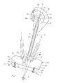
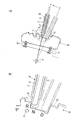
第1実施の形態を図1乃至図4を参照して説明する。図1はシフトレバー装置の概要を示す側面図、図2はシフトレバー装置の要部を模式的に示す説明図である。なお、図中矢印Fは車体前方方向を示す。
(First embodiment)
A first embodiment will be described with reference to FIGS. FIG. 1 is a side view showing an outline of a shift lever device, and FIG. 2 is an explanatory view schematically showing a main part of the shift lever device. In the figure, an arrow F indicates the front direction of the vehicle body.
図中符号1は車体フロアに取り付けられるベースとなる下部支持体であって、下部支持体1の上部に上部支持体2が設けられる。上部支持体2の上面に図示しないシフトゲートが開口する。
一方、下部支持体1には、軸線が車幅方向に延在する回転軸3が回転自在に軸支されている。回転軸3にケーブル取付アーム4の基端が固定されると共に、ケーブル取付アーム4の先端は下方に延在してセレクトケーブル5によって図示しない自動変速機制御装置に連結される。
On the other hand, a
回転軸3には、図示しないジョイントを介してシフトレバー10が設けられる。シフトレバー10は、回転軸3に設けられる図示しないレバーブラケットと、基端がレバーブラケットに結合された管状のレバーパイプ11とによって形成され、レバーパイプ11の先端に中空状のグリップ12が設けられる。
The
図2に示すように、シフトレバー10のレバーパイプ11内に軸方向となる上下動自在に嵌挿すると共に先端16がレバーパイプ11の基端から下方に突出し、基端17がレバーパイプ11の基端から突出してグリップ12内に突出するガイドロッド15を有する。
As shown in FIG. 2, the
ガイドロッド15の基端17に係止孔17aが開口し、グリップ12内に上下揺動自在に軸支されて図示しないスプリングによって下方に揺動付勢された揺動アーム18の先端に係止孔17aが係止される。
A locking
グリップ12の前面の開口部に操作ボタン19が揺動自在に設けられ、操作ボタン19をグリップ12の内方に押動することで揺動アーム18の先端が上方に揺動してガイドロッド15が上昇移動してガイドロッド15の先端16がレバーパイプ11内に収納される退避位置に移動する。一方、操作ボタン19の押動を解除することで、揺動アーム18が下方に揺動してガイドロッド15の先端16がレバーパイプ11の基端から突出する作動位置に移動すると共に、操作ボタン19をグリップ12の前方に押し出す。なお、退避位置におけるガイドロッド15、揺動アーム18、操作ボタン19を仮想線15a、18a、19aで示す。
An
このように、シフトレバー10は、下部支持体1に軸支された回転軸3を中心に車体前後方向のシフト方向に回転自在に支持され、操作ボタン19をグリップ12の内方に押すことによってガイドロッド15がレバーパイプ11に沿って退避位置に上昇移動し、操作ボタン19の押圧を解除することによってガイドロッド15が作動位置まで下降する。
As described above, the
下部支持体1には、シフトレバー10をシフト方向に沿って操作位置となるPポジション、Rポジション、Nポジション、Dポジションの各シフトポジションに節度をもって保持する図示しないディテント機構が設けられる。
The
下部支持体1には、車幅方向に軸心が延在する軸27によってガイドプレート21がシフト方向に揺動可能に軸支される。
A
ガイドプレート20は、図2に示すようにシフト方向に長い下縁21、上縁22及び前縁23、後縁24を有する板状であって、上縁22にガイドロッド15の先端16が挿入可能で、かつ先端16のシフト方向の移動範囲を所定の高さ位置で規制する縁部形状のガイド25が形成される。ガイド25は、シフトレバー10の各シフトポジションに対応してPポジション、Rポジション、Nポジション、Dポジションがシフト方向に列設され、PポジションとRポジションとの間に突起Tが形成され、RポジションとNポジションとの間に階段状のストッパ面Sが形成され、Rポジションに対してNポジション及びDポジションが低位置に連続形成される。
As shown in FIG. 2, the
この縁部形状のガイド25が形成されたガイドプレート20は、シフト方向におけるRポジション近傍でかつストッパ部Sより下縁21側となるガイドプレート20のほぼ中央部が、車幅方向に軸心が延在する軸27によって下部支持体1にシフト方向に揺動乃至回動自在に軸支される。
The
更に、下部支持体1とガイドプレート20の下縁21の前端近傍の前端側位置21aとの間にガイドプレート20の前端側を上方に押圧付勢する第1付勢手段となる第1スプリング28がボール28aを介在して圧縮付与状態で装着される。更に、下部支持体1とガイドプレート20の下縁21の後端近傍の後端側位置21bとの間にガイドプレート20の後端側を上方に押圧付勢する第2付勢手段となる第2スプリング29がボール29aを介在して圧縮付与状態で装着される。この軸27を介して互いにシフト方向に離反した前端側及び後端側にそれぞれ配設された第1スプリング28と第2スプリング29による押圧付勢によってガイドプレート20の揺動が抑制されてガイドプレート20が所期の通常位置に付勢保持される。これら軸27及び第1スプリング28、第2スプリング29によってガイドプレート20を通常位置に付勢して下部支持体1に保持する支持手段26を構成する。
Further, a
このガイドプレート20が通常位置にあって、シフトレバー10がPポジションにおいては作動位置に下降したガイドロッド15の先端16はガイドプレート20に形成されたガイド25のPポジションに位置し、グリップ12に設けられた操作ボタン19を押してガイドロッド15を上昇移動することによって先端16と突起部Tのストッパ面TSとの当接が回避されて、PポジションからRポジション、NポジションやDポジション等の他のシフトポジションへ切り換えができる。また、DポジションからNポジションを介してRポジションにシフト操作するにあたり、操作ボタン19を押してガイドロッド15を上昇移動することで階段状のストッパ面Sとの当接が回避されてシフト操作を可能にすることでRポジションへ切り換えられる。
When the
一方、ガイドプレート20のガイド25に予め設定された衝撃荷重を上回る過大なシフト方向の衝撃荷重が加えられた際、例えば、ストッパ面SにDポジション側からのシフト方向の過大な衝撃荷重が加えられたときには、ストッパ面Sがシフト方向に押動されて、第1スプリング28の付勢に抗して第1スプリング28を圧縮付与しつつ第2スプリング29が伸張してガイドプレート20が軸27を中心にシフト方向に傾動し、かつ衝撃荷重が予め設定された過大な衝撃荷重を下回る状態になると第1スプリング28、第2スプリング29による付勢によって通常位置に復帰する。
On the other hand, when an excessive impact load in the shift direction exceeding the preset impact load is applied to the
また、突起Tのストッパ面TSにPポジション側からシフト方向の過大な荷重が加えられたときには、ストッパ面TSがシフト方向に押動されて第2スプリング29の付勢に抗して第2スプリング29を圧縮付与しつつ第1スプリング28が伸張してガイドプレート20が軸27を中心にシフト方向に揺動し、かつ衝撃荷重が予め設定された過大な衝撃荷重を下回る状態になると第1スプリング28、第2スプリング29による付勢によって通常位置に復帰する。
Further, when an excessive load in the shift direction is applied to the stopper surface TS of the protrusion T from the P position side, the stopper surface TS is pushed in the shift direction and resists the bias of the
次に、このように構成されたシフトレバー装置の作動について説明する。 Next, the operation of the shift lever device configured as described above will be described.
車両運転開始前や駐車等において、シフトレバー10がPポジションにあるとする。このシフトレバー10がPポジションにおいては、ガイドロッド15の先端16が図2に仮想線16pで示すようにガイドプレート20の上縁22に形成されたガイド25のPポジションに位置すると共にディテント機構によってシフトレバー10がPポジションに保持され、かつケーブル取付アーム4がPポジションに維持される。
It is assumed that the
このシフトレバー10がPポジションにある状態で運転者等が不意にシフトレバー10をシフト方向に操作した際、すなわち操作ボタン19を押すことなくシフトレバー10をシフト方向に操作したときには、ガイドロッド15の先端16が突起Tのストッパ面TSに当接して移動が阻止されて他のシフトポジション、例えばRポジションやDポジション等へ切り換えが阻止される。同様にシフトレバー10等に搭載物等が接触した際にも他のシフトポジションへの切り換えが阻止される。
When the driver or the like unexpectedly operates the
走行等にあたり、Pポジションにおいて、グリップ12に設けられた操作ボタン19を押してガイドロッド15を退避位置に上昇移動させることで、ガイドロッド15の先端16と突起Tとの当接が解除されてシフトレバー10をRポジションやDポジション等の他のシフトポジションへのシフト操作することができる。このシフト操作に伴ってケーブル取付アーム4がRポジションやDポジション等の他のシフトポジションに切り換えられる。
When traveling, for example, at the P position, the
また、走行中等におけるシフトレバー10がDポジションにおいては、ガイドロッド15の先端16が図2に仮想線16dで示すように、ガイドプレート20の上縁22に形成されたガイド25のDポジションに位置すると共にディテント機構によってシフトレバー10がDポジションに保持され、かつケーブル取付アーム4がDポジションに維持される。
Further, when the
このシフトレバー10がDポジションにある状態で運転者等が不意にシフトレバー10をRポジション方向にシフト操作した際、すなわち操作ボタン19を押すことなくシフトレバー10をシフト操作したときには、ガイドロッド15の先端16がストッパ面Sに当接して移動が阻止されて他のシフトポジション、例えばRポジション等へのシフト操作が阻止される。同様にシフトレバー10等に搭載物等が接触した際にも他のシフトポジションへの切り換えが阻止される。
When the driver or the like unexpectedly shifts the
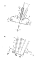
一方、図3(a)に仮想線で示すようにシフトレバー10がDポジションにある状態で、運転者等が不意に、シフトレバー10を予め設定された操作荷重を上回る過大な操作荷重でRポジション或いはPポジション方向にシフト操作する状態、すなわち操作ボタン19を押すことなくシフトレバー10をシフト操作したときには、ガイドロッド15の先端16がストッパ面Sに激しく当接して押動する。このガイドロッド15の当接によりストッパ面Sに衝撃荷重が入力されてガイドプレート20が図3(a)に示すように軸27を中心に第1スプリング2を圧縮しつつ揺動してストッパ面Sがシフト方向に移動しつつ衝撃を吸収する。
On the other hand, as shown by the phantom line in FIG. 3A, in the state where the
このとき、図3(b)に示すようにガイドプレート20の揺動に伴ってストッパ面Sがシフト方向に移動すると共にガイドロッド15の先端16の当接方向となるシフト方向に対して傾動し、この傾斜するストッパ面Sによってガイドロッド15の先端16をストッパ面Sに沿って上方に誘導することでストッパ面Sに作用する衝撃荷重が減少してストッパ面Sの破損乃至損傷を回避する。
At this time, as shown in FIG. 3B, the stopper surface S moves in the shift direction as the
一方、シフトレバー10のガイドロッド15の先端16からストッパ面Sに加えられる衝撃荷重が、予め設定された衝撃荷重を下回る状態になると、第1スプリング28及び第2スプリング29の復元力によってガイドプレート20が回動して通常位置に復帰する。
On the other hand, when the impact load applied to the stopper surface S from the
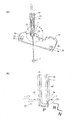
同様に、図4(a)に仮想線で示すようにシフトレバー10がPポジションにある状態で、運転者等が不意に、シフトレバー10を予め設定された操作荷重を上回る過大な操作荷重でRポジションやDポジション方向にシフト操作する状態、すなわち操作ボタン19を押すことなくシフトレバー10をシフト操作したときには、ガイドロッド15の先端16が突起Tのストッパ面TSに激しく当接して押動する。このガイドロッド15の当接により突起Tに衝撃荷重が入力されてガイドプレート20が図4(a)に示すように軸27を中心に第2スプリング29を圧縮しつつ揺動して衝撃を減少させる。
Similarly, as shown by the phantom line in FIG. 4A, in a state where the
このとき、図4(b)に示すようにガイドプレート20の揺動に伴って突起Tのストッパ面TSがシフト方向に移動すると共にガイドロッド15の先端16の当接方向となるシフト方向に対して傾斜し、この傾斜する突起Tのストッパ面TSによってガイドロッド15の先端16をストッパ面TSに沿って上方に誘導することでストッパ面TSに作用する衝撃が減少して突起Tの破損乃至損傷を回避する。
At this time, as shown in FIG. 4B, the stopper surface TS of the protrusion T moves in the shift direction as the
一方、シフトレバー10のガイドロッド15の先端16から突起Tに加えられる衝撃荷重が、予め設定された衝撃荷重を下回る状態になると、第1スプリング28及び第2スプリング29の復元によってガイドプレート20が回動して通常状態に復帰する。
On the other hand, when the impact load applied to the protrusion T from the
従って、このシフトレバー装置によれば、ガイドプレート20を下部支持体1に軸27によって回動可能に支持し、下部支持体1とガイドプレート20の下縁21の前端側位置21a及び後端側位置21bとの間に、ガイドプレート20の前端側及び後端側を上方に押圧付勢してガイドプレート20を所期の通常位置に付勢保持する第1スプリング28と第2スプリング29を装着する簡単な構成で、例えば、操作ボタン19を押し操作することなくシフトレバー10を設定された操作荷重を上回る過大な操作荷重でシフト方向に操作してガイドロッド15がストッパ面Sに設定された衝撃荷重で激しく当接した際に、ストッパ面Sがシフト方向に移動するように第1スプリング28及び第2スプリング29の付勢に抗してガイドプレート20が移動して衝撃荷重を吸収することで、シフトレバー装置の構成部材への衝撃が減少して衝撃から保護されて構成部材等の損傷が防止できる。一方、衝撃が設定された衝撃荷重を下回ると第1付勢手段及び第2付勢手段の付勢によりガイドプレート20が通常位置に復帰される。
Therefore, according to this shift lever device, the
(第2実施の形態)
第2実施の形態を図5乃至図7を参照して説明する。図5は第2実施の形態におけるシフトレバー装置の要部を模式的に示す図、図6及び図7は作動説明図である。なお、図5乃至図7において上記図1乃至図4と対応する部分には同一符号を付することで、該部の詳細な説明を省略する。
(Second Embodiment)
A second embodiment will be described with reference to FIGS. FIG. 5 is a diagram schematically showing the main part of the shift lever device according to the second embodiment, and FIGS. 6 and 7 are operation explanatory views. 5 to 7, parts corresponding to those in FIGS. 1 to 4 are denoted by the same reference numerals, and detailed description thereof is omitted.
図5に示すように、ガイドプレート20は、シフト方向に長い下縁21、上縁22及び前縁23、後縁24を有する板状であって、上縁22にガイドロッド15の先端16が挿入可能で、かつ先端16のシフト方向の移動範囲を所定の高さ位置で規制するガイド25が形成される。ガイド25は、シフトレバー10の各シフトポジションに対応してPポジション、Rポジション、Nポジション、Dポジションがシフト方向に列設され、PポジションとRポジションとの間に突起Tが形成され、RポジションとNポジションとの間に階段状のストッパ面Sが形成され、Rポジションに対してNポジション及びDポジションが低位置に連続形成される。ガイドプレート20の前端近傍でかつガイド25より下方となる下縁21の近傍位置に上下方向が長径の第1取付孔31を有し、後端近傍でかつガイド25より下方となる下縁21の近傍位置に上下方向に長径の第2取付孔32を有する。
As shown in FIG. 5, the
ガイドプレート20は、前側が第1取付孔31に上下側が肉厚のゴム等の弾性体からなる上下方向に弾性変形可能な第1ブッシュ33を介在して貫通する軸状取付具である取付ボルト35によって下部支持体1に取り付けられ、後側が第2取付孔32に上下側が肉厚のゴム等の弾性体からなる上下方向に弾性変形可能な第2ブッシュ34を介在して貫通する軸状取付具である取付ボルト36によって下部支持体1に取り付けられて所期の通常位置に保持される。
The
この通常状態において、シフトレバー10がPポジションにおいては作動位置に下降したガイドロッド15の先端16はガイドプレート20に形成されたガイド25のPポジションに位置し、グリップ12に設けられた操作ボタン19を押してガイドロッド15を上昇移動することによって先端16と突起部Tとの当接が回避されて、PポジションからRポジション、NポジションやDポジション等の他のシフトポジションへシフト操作ことができる。また、DポジションからNポジションを介してRポジションに切換操作にあたり、操作ボタン19を押してガイドロッド15を上昇移動することで階段状のストッパ面Sとの当接を回避することでRポジションへシフトすることができる。
In this normal state, when the
一方、ガイドプレート20のガイド25に予め設定された衝撃荷重を上回る過大なシフト方向の荷重が加えられたとき、例えば、ストッパ面SにDポジション側からのシフト方向の衝撃荷重が加えられたときには、ストッパ面Sがシフト方向に押動されてガイドプレート20が第1取付孔31に装着された第1ブッシュ33及び第2取付孔32に装着された第2ブッシュ34を圧縮変形して前下がり状態に傾斜する。また、過大な荷重付与が解除されると第1ブッシュ33及び第2ブッシュ34の復元によって通常位置に復帰する。
On the other hand, when an excessive shift direction load exceeding the preset impact load is applied to the
また、突起Tのストッパ面TSにPポジション側からシフト方向の過大な衝撃荷重が加えられたときには、その荷重付与により突起Tがシフト方向に押動されてガイドプレート20が第1取付孔31に装着された第1ブッシュ33及び第2取付孔32に装着された第2ブッシュ34を圧縮変形して後下がりに傾斜する。また、過大な荷重付与が解除されると第1ブッシュ33及び第2ブッシュ34の復元によって通常位置に復帰する。この第1取付孔31及び第2取付孔32に装着される第1ブッシュ33及び第2ブッシュ34によってガイドプレート20を通常位置に付勢して保持する支持手段30を構成する。
When an excessive impact load in the shift direction is applied to the stopper surface TS of the protrusion T from the P position side, the protrusion T is pushed in the shift direction by applying the load, and the
次に、このように構成されたシフトレバー装置の作動について説明する。 Next, the operation of the shift lever device configured as described above will be described.
車両運転開始前や駐車等において、シフトレバー10がPポジションにあるとする。このシフトレバー10がPポジションにおいては、ガイドロッド15の先端16が図5に仮想線16pで示すようにガイドプレート20の上縁22に形成されたガイド25のPポジションに位置すると共にディテント機構によってシフトレバー10がPポジションに保持され、かつケーブル取付アーム4がPポジションに維持される。
It is assumed that the
このシフトレバー10がPポジションにある状態で運転者等が不意にシフトレバー10をシフト方向に操作した際、すなわち操作ボタン19を押すことなくシフトレバー10をシフト方向に操作したときには、ガイドロッド15の先端16が突起Tに当接して移動が阻止されて他のシフトポジション、例えばRポジション等へのシフト操作が阻止される。同様にシフトレバー10等に搭載物等が接触した際にも他のシフトポジションへの切換えが阻止される。
When the driver or the like unexpectedly operates the
走行等にあたり、Pポジションにおいて、グリップ12に設けられた操作ボタン19を押してガイドロッド15を退避位置に上昇移動させることで、ガイドロッド15の先端16と突起Tとの当接が解除されてシフトレバー10をRポジションやDポジション等の他のレンジポジションへの切り換え操作することができる。
When traveling, for example, at the P position, the
また、走行中等におけるシフトレバー10がDポジションにおいては、ガイドロッド15の先端16が図5に仮想線16dで示すようにガイドプレート20の上縁22に形成されたガイド25のDポジションに位置すると共にディテント機構によってシフトレバー10がDポジションに保持される。
Further, when the
このシフトレバー10がDポジションにある状態で運転者等が不意にシフトレバー10をシフト方向に操作した際、すなわち操作ボタンを押すことなくシフトレバー10をシフト方向に操作したときには、ガイドロッド15の先端16がストッパ面Sに当接して移動が阻止されてRポジション等へのシフト操作が阻止される。同様にシフトレバー10がDポジションにある状態でシフトレバー10等に搭載物等が接触した際にもRポジションへの切換えが阻止される。
When the driver or the like unexpectedly operates the
一方、図6(a)に仮想線で示すようにシフトレバー10がDポジションにある状態で、運転者等が不意に、シフトレバー10を予め設定された操作荷重を上回る過大な操作荷重でRポジション或いはPポジション方向にシフト操作する、すなわち操作ボタン19を押すことなくシフトレバー10をシフト操作したときには、ガイドロッド15の先端16がストッパ面Sに激しく当接して押動する。このガイドロッド15の当接によりストッパ面Sに衝撃荷重が入力されてガイドプレート20が図6(a)に示すように、ガイドプレート20が第1取付孔31に装着された第1ブッシュ33及び第2取付孔32に装着され第2ブッシュ34を圧縮変形させて前下がりに傾斜して衝撃を減少させる。
On the other hand, as shown by the phantom line in FIG. 6A, in the state where the
このとき、図6(b)に示すようにガイドプレート20の揺動に伴ってストッパ面Sがシフト方向に移動すると共にガイドロッド15の先端16の当接方向となるシフト方向に対して傾動し、この傾斜するストッパ面Sによってガイドロッド15の先端16をストッパ面Sに沿って上方に誘導することでストッパ面Sに作用する衝撃を減少されてストッパ面Sの破損乃至損傷を回避する。
At this time, as shown in FIG. 6B, the stopper surface S moves in the shift direction along with the swing of the
一方、シフトレバー10のガイドロッド16の先端16からストッパ面Sに加えられる衝撃荷重が、予め設定された衝撃荷重を下回る状態になると、第1ブッシュ33及び第2ブッシュ34が復元してガイドプレート20が通常位に復帰する。
On the other hand, when the impact load applied to the stopper surface S from the
同様に、図7に(a)に仮想線で示すようにシフトレバー10がPポジションにある状態で、運転者等が不意に、シフトレバー10を予め設定された操作荷重を上回る過大な操作荷重でRポジションやDポジション方向にシフト操作する、すなわち操作ボタンを押すことなくシフトレバー10をシフト方向に操作したときには、ガイドロッド15の先端16が突起Tのストッパ面TSに激しく当接して押動する。このガイドロッド15の当接により突起Tのストッパ面TSに衝撃荷重が入力されてガイドプレート20が図7(a)に示すようにガイドプレート20の第1取付孔31に装着された第1ブッシュ33及び第2取付孔32に装着された第2ブッシュ34を圧縮変形して前上がりに傾斜して衝撃を吸収する。
Similarly, as shown by the phantom line in FIG. 7 (a), in the state where the
このとき、図7(b)に示すようにガイドプレート20の傾動に伴って突起Tのストッパ面TSがガイドロッド15の先端16の当接方向となるシフト方向に対して傾動し、この傾斜する突起Tのストッパ面TSによってガイドロッド15を上方に誘導して突起Tの破損乃至損傷を回避する。
At this time, as shown in FIG. 7B, the stopper surface TS of the protrusion T tilts with respect to the shift direction that is the contact direction of the
一方、シフトレバー10のガイドロッド16の先端16から突起Tに加えられる衝撃荷重が、予め設定された衝撃荷重を下回る状態になると、第1ブッシュ33及び第2ブッシュ34の復元力によってガイドプレート20が回動して通常状態に復帰する。
On the other hand, when the impact load applied to the projection T from the
従って、このシフトレバー装置によれば、ガイドプレート20を下部支持体1に第1ブッシュ33及び第2ブッシュ34を介してガイドプレート20が所期の通常位置に保持され、例えば、操作ボタン19を操作することなくシフトレバー10を設定された操作荷重を上回る過大な操作荷重でシフト方向に操作してガイドロッド15がストッパ面Sに設定された衝撃荷重で激しく当接した際に、ストッパ面Sがシフト方向に移動するように第1ブッシュ33及び第2ブッシュ34の付勢に抗してガイドプレート20が移動して衝撃荷重を吸収することで、シフトレバー装置の構成部材への衝撃が減少して衝撃から保護されて構成部材等の損傷が防止できる。一方、衝撃が設定された衝撃荷重を下回ると第1ブッシュ33及び第2ブッシュ34の復元によりガイドプレートが通常位置に復帰される。
Therefore, according to this shift lever device, the
なお、本発明は上記実施の形態に限定されることなく、発明の趣旨を逸脱しない範囲で種々変更可能である。例えば上記実施の形態では、シフトレバーの上部に設けられた操作ボタンの押し操作に応じて軸方向に移動するガイドロッドと、シフトポジションがシフト方向に列設されてガイドロッドのシフト方向の移動範囲を規制する上縁部形状を有するガイドが形成されたガイドプレートを備えた場合について説明したが、シフトレバーの上部に設けられた操作ボタンの押し操作に応じて軸方向に移動するガイドロッドに設けられたポジションピンを、シフトポジションがシフト方向に列設されてポジションピンのシフト方向の移動範囲を規制する上縁部形状を有するガイドが形成されたガイドプレートを備えたシフトレバー装置においても同様に構成することができる。 In addition, this invention is not limited to the said embodiment, A various change is possible in the range which does not deviate from the meaning of invention. For example, in the above-described embodiment, the guide rod that moves in the axial direction in response to the pressing operation of the operation button provided on the upper portion of the shift lever, and the shift position of the guide rod that is arranged in the shift direction are moved in the shift direction of the guide rod. In the above description, the guide plate having a guide having an upper edge shape that restricts the movement is provided. However, the guide plate is provided on the guide rod that moves in the axial direction in response to the pressing operation of the operation button provided on the upper portion of the shift lever. Similarly, in a shift lever device having a guide plate having a guide having an upper edge shape in which the shift position is arranged in the shift direction and the movement range of the position pin in the shift direction is regulated. Can be configured.
1 下部支持体(ベース)
2 上部支持体
3 回転軸
10 シフトレバー
11 レバーパイプ
12 グリップ
15 ガイドロッド
16 先端
17 基端
18 揺動アーム
19 操作ボタン
20 ガイドプレート
21 下縁
21a 前端側位置
21b 後端側位置
22 上縁
23 前縁
24 後縁
25 ガイド
P Pポジション(シフトポジション)
R Rポジション(シフトポジション)
N Nポジション(シフトポジション)
D Dポジション(シフトポジション)
S ストッパ面
T 突起
TS ストッパ面
26 支持手段
27 軸
28 第1スプリング(第1付勢手段)
29 第2スプリング(第2付勢手段)
30 支持手段
31 第1取付孔
32 第2取付孔
33 第1ブッシュ
34 第2ブッシュ
35、36 取付ボルト(軸状取付具)
1 Lower support (base)
2
R R position (shift position)
N N position (shift position)
D D position (shift position)
S Stopper surface T Protrusion
29 Second spring (second biasing means)
30 support means 31 first mounting
Claims (4)
前記支持手段は、前記ストッパ面に予め設定された衝撃荷重を上回る衝撃荷重が加えられた際に、該ストッパ面をシフト方向に移動可能にガイドプレートを支持し、前記ストッパ面に加えられる衝撃荷重が前記設定された衝撃荷重を下回る状態になると前記ガイドプレートを通常位置に復帰させることを特徴とする自動変速機のシフトレバー装置。 A shift lever that swings in the shift direction about a rotation shaft provided on a base fixed to the vehicle body, and is inserted in the shift lever, and in the axial direction according to an operation of an operation button provided on the shift lever. A guide rod that moves, and a stopper surface that is supported by a support means on a base and that is arranged in the shift direction and serves as an operation position for the shift lever, and a stopper surface that regulates the movement range of the guide rod in the shift direction An automatic transmission that includes a guide plate formed with an edge-shaped guide and that allows the shift lever to move in the shift direction by avoiding contact between the guide rod and the stopper surface by operating the operation button. In the shift lever device,
The support means supports the guide plate so that the stopper surface can be moved in the shift direction when an impact load exceeding a preset impact load is applied to the stopper surface, and the impact load applied to the stopper surface. A shift lever device for an automatic transmission, wherein the guide plate is returned to a normal position when the state becomes less than the set impact load.
前記ベースにガイドプレートをシフト方向に揺動自在に軸支し、
該軸を隔てた互いにシフト方向に離反したガイドプレートの両端側とベースとの間にそれぞれ圧縮付与状態で装着されて前記ガイドプレートを通常位置に付勢する第1付勢手段と第2付勢手段とを備えたことを特徴とする請求項1または2に記載の自動変速機のシフトレバー装置。 The support means is
A guide plate is pivotally supported on the base so as to be swingable in the shift direction.
A first urging means and a second urging means, which are mounted in a compressed state between both ends of the guide plate and the base, which are separated from each other in the shift direction, with the shaft therebetween, and urge the guide plate to the normal position. The shift lever device for an automatic transmission according to claim 1 or 2, further comprising: means.
前記ガイドプレートにシフト方向に離反して形成された長径の第1取付孔及び第2取付孔を有し、
ベースに取り付けられる第1軸状取付具及び第2軸状取付具と、
前記ガイドプレートの第1取付孔と第1軸状取付具との間に介在する弾性変形可能な第1ブッシュ及び第1取付孔と第2軸状取付具との間に介在する弾性変形可能な第2ブッシュとを備え、
ガイドプレートが前記第1取付孔及び第2取付孔にそれぞれ第1ブッシュおよび第2ブッシュを介在して貫通する第1軸状部材および第2軸状部材によってベースに取り付けられたことを特徴とする請求項1または2に記載の自動変速機のシフトレバー装置。 The support means has a first mounting hole and a second mounting hole having a long diameter formed away from the guide plate in the shift direction,
A first axial fixture and a second axial fixture attached to the base;
An elastically deformable first bushing interposed between the first mounting hole and the first shaft-shaped mounting tool of the guide plate and an elastically deformable material interposed between the first mounting hole and the second shaft-shaped mounting tool. A second bush,
A guide plate is attached to the base by a first shaft-like member and a second shaft-like member that penetrate the first and second attachment holes with a first bush and a second bush, respectively. The shift lever device for an automatic transmission according to claim 1 or 2.
Priority Applications (1)
| Application Number | Priority Date | Filing Date | Title |
|---|---|---|---|
| JP2013267792A JP6220667B2 (en) | 2013-12-25 | 2013-12-25 | Shift lever device for automatic transmission |
Applications Claiming Priority (1)
| Application Number | Priority Date | Filing Date | Title |
|---|---|---|---|
| JP2013267792A JP6220667B2 (en) | 2013-12-25 | 2013-12-25 | Shift lever device for automatic transmission |
Publications (3)
| Publication Number | Publication Date |
|---|---|
| JP2015123787A true JP2015123787A (en) | 2015-07-06 |
| JP2015123787A5 JP2015123787A5 (en) | 2016-11-04 |
| JP6220667B2 JP6220667B2 (en) | 2017-10-25 |
Family
ID=53534838
Family Applications (1)
| Application Number | Title | Priority Date | Filing Date |
|---|---|---|---|
| JP2013267792A Expired - Fee Related JP6220667B2 (en) | 2013-12-25 | 2013-12-25 | Shift lever device for automatic transmission |
Country Status (1)
| Country | Link |
|---|---|
| JP (1) | JP6220667B2 (en) |
Citations (8)
| Publication number | Priority date | Publication date | Assignee | Title |
|---|---|---|---|---|
| JPS6264636U (en) * | 1985-10-12 | 1987-04-22 | ||
| JPH0196015U (en) * | 1987-12-16 | 1989-06-26 | ||
| JPH0329758U (en) * | 1989-07-31 | 1991-03-25 | ||
| JPH0452651U (en) * | 1990-09-07 | 1992-05-06 | ||
| JPH0569754A (en) * | 1991-09-10 | 1993-03-23 | Toyota Motor Corp | Shift lever support device |
| JPH06316227A (en) * | 1993-05-07 | 1994-11-15 | Nippon Cable Syst Inc | Manual type transmission operating device |
| JPH0834259A (en) * | 1994-07-20 | 1996-02-06 | Delta Kogyo Co Ltd | Guide plate mounting structure of vehicle shift lever device |
| JPH0834258A (en) * | 1994-07-20 | 1996-02-06 | Delta Kogyo Co Ltd | Shift lever mounting structure for vehicle shift lever device |
-
2013
- 2013-12-25 JP JP2013267792A patent/JP6220667B2/en not_active Expired - Fee Related
Patent Citations (8)
| Publication number | Priority date | Publication date | Assignee | Title |
|---|---|---|---|---|
| JPS6264636U (en) * | 1985-10-12 | 1987-04-22 | ||
| JPH0196015U (en) * | 1987-12-16 | 1989-06-26 | ||
| JPH0329758U (en) * | 1989-07-31 | 1991-03-25 | ||
| JPH0452651U (en) * | 1990-09-07 | 1992-05-06 | ||
| JPH0569754A (en) * | 1991-09-10 | 1993-03-23 | Toyota Motor Corp | Shift lever support device |
| JPH06316227A (en) * | 1993-05-07 | 1994-11-15 | Nippon Cable Syst Inc | Manual type transmission operating device |
| JPH0834259A (en) * | 1994-07-20 | 1996-02-06 | Delta Kogyo Co Ltd | Guide plate mounting structure of vehicle shift lever device |
| JPH0834258A (en) * | 1994-07-20 | 1996-02-06 | Delta Kogyo Co Ltd | Shift lever mounting structure for vehicle shift lever device |
Also Published As
| Publication number | Publication date |
|---|---|
| JP6220667B2 (en) | 2017-10-25 |
Similar Documents
| Publication | Publication Date | Title |
|---|---|---|
| JP4254616B2 (en) | Position adjustment device for vehicle armrest | |
| JP2011106265A (en) | Safety door handle | |
| US20120048050A1 (en) | Shift lever device | |
| JP2009174916A (en) | Suspension device | |
| JP6220667B2 (en) | Shift lever device for automatic transmission | |
| US20190063592A1 (en) | Damping mechanism for a shift selector assembly and a shift selector assembly comprising the damping mechanism | |
| JP6642275B2 (en) | Vehicle seat | |
| JP2008105584A (en) | Shift lever device | |
| JP4535457B2 (en) | Entrance / exit blocking device for work machine | |
| US7204516B2 (en) | Telescope wedge locking mechanism | |
| GB2428190A (en) | Locking mechanism for castor | |
| JP5147615B2 (en) | Stabilizer | |
| JP4496941B2 (en) | Brake pedal device for vehicle | |
| JP4506176B2 (en) | Steering column device | |
| JP2012036987A (en) | Parking lock device of transmission | |
| US20040173400A1 (en) | Steering equipment for vehicles | |
| JP6641568B2 (en) | Vehicle slide rail device | |
| JP4172694B2 (en) | Steering column device | |
| JP4053521B2 (en) | Combination switch device | |
| JP4402518B2 (en) | Vehicle direction indication device | |
| JP4988879B2 (en) | Working vehicle | |
| KR100803429B1 (en) | Vehicle parking assembly | |
| KR100705138B1 (en) | Shifting lever assembly of the manual transmission for the bus | |
| KR101439155B1 (en) | Structure for movement prevention of gearshift-lever when rear-end collision occurs | |
| JP2006273315A (en) | Vehicle steering column structure |
Legal Events
| Date | Code | Title | Description |
|---|---|---|---|
| A521 | Request for written amendment filed |
Free format text: JAPANESE INTERMEDIATE CODE: A523 Effective date: 20160915 |
|
| A621 | Written request for application examination |
Free format text: JAPANESE INTERMEDIATE CODE: A621 Effective date: 20160915 |
|
| A977 | Report on retrieval |
Free format text: JAPANESE INTERMEDIATE CODE: A971007 Effective date: 20170426 |
|
| A131 | Notification of reasons for refusal |
Free format text: JAPANESE INTERMEDIATE CODE: A131 Effective date: 20170502 |
|
| A521 | Request for written amendment filed |
Free format text: JAPANESE INTERMEDIATE CODE: A523 Effective date: 20170607 |
|
| TRDD | Decision of grant or rejection written | ||
| A01 | Written decision to grant a patent or to grant a registration (utility model) |
Free format text: JAPANESE INTERMEDIATE CODE: A01 Effective date: 20170905 |
|
| A61 | First payment of annual fees (during grant procedure) |
Free format text: JAPANESE INTERMEDIATE CODE: A61 Effective date: 20171002 |
|
| R150 | Certificate of patent or registration of utility model |
Ref document number: 6220667 Country of ref document: JP Free format text: JAPANESE INTERMEDIATE CODE: R150 |
|
| R250 | Receipt of annual fees |
Free format text: JAPANESE INTERMEDIATE CODE: R250 |
|
| R250 | Receipt of annual fees |
Free format text: JAPANESE INTERMEDIATE CODE: R250 |
|
| R250 | Receipt of annual fees |
Free format text: JAPANESE INTERMEDIATE CODE: R250 |
|
| LAPS | Cancellation because of no payment of annual fees |