JP2015137807A - Cold storage heat exchanger - Google Patents
Cold storage heat exchanger Download PDFInfo
- Publication number
- JP2015137807A JP2015137807A JP2014009869A JP2014009869A JP2015137807A JP 2015137807 A JP2015137807 A JP 2015137807A JP 2014009869 A JP2014009869 A JP 2014009869A JP 2014009869 A JP2014009869 A JP 2014009869A JP 2015137807 A JP2015137807 A JP 2015137807A
- Authority
- JP
- Japan
- Prior art keywords
- cold storage
- refrigerant
- ester compound
- heat exchanger
- header
- Prior art date
- Legal status (The legal status is an assumption and is not a legal conclusion. Google has not performed a legal analysis and makes no representation as to the accuracy of the status listed.)
- Granted
Links
Images



Classifications
-
- Y—GENERAL TAGGING OF NEW TECHNOLOGICAL DEVELOPMENTS; GENERAL TAGGING OF CROSS-SECTIONAL TECHNOLOGIES SPANNING OVER SEVERAL SECTIONS OF THE IPC; TECHNICAL SUBJECTS COVERED BY FORMER USPC CROSS-REFERENCE ART COLLECTIONS [XRACs] AND DIGESTS
- Y02—TECHNOLOGIES OR APPLICATIONS FOR MITIGATION OR ADAPTATION AGAINST CLIMATE CHANGE
- Y02E—REDUCTION OF GREENHOUSE GAS [GHG] EMISSIONS, RELATED TO ENERGY GENERATION, TRANSMISSION OR DISTRIBUTION
- Y02E60/00—Enabling technologies; Technologies with a potential or indirect contribution to GHG emissions mitigation
- Y02E60/14—Thermal energy storage
Landscapes
- Heat-Exchange Devices With Radiators And Conduit Assemblies (AREA)
- Air-Conditioning For Vehicles (AREA)
Abstract
Description
本発明は、冷凍サイクル装置に用いられる蓄冷熱交換器に関するものである。 The present invention relates to a cold storage heat exchanger used in a refrigeration cycle apparatus.
車両用空調装置では、走行用エンジンによって冷凍サイクル装置が駆動される。このため、車両が一時的に停車している間にエンジンが停止すると、冷凍サイクル装置が停止することになる。燃費の向上を図るため、信号待ち等の車両停止中にエンジンを停止する、いわゆるアイドルストップ車が増加している。このようなアイドルストップ車では、車両停車中(エンジン停止中)に冷凍サイクル装置が停止することで車室内の快適性を損なうという問題がある。また空調感を維持するために車両停止中においてもエンジンを再起動させると、燃費の向上の妨げになるという問題もある。 In the vehicle air conditioner, the refrigeration cycle apparatus is driven by the traveling engine. For this reason, if the engine is stopped while the vehicle is temporarily stopped, the refrigeration cycle apparatus is stopped. In order to improve fuel efficiency, so-called idle stop vehicles that stop the engine while the vehicle is stopped, such as waiting for a signal, are increasing. In such an idle stop vehicle, there is a problem that the refrigeration cycle apparatus stops while the vehicle is stopped (the engine is stopped), thereby impairing the comfort in the passenger compartment. In addition, there is also a problem that if the engine is restarted even when the vehicle is stopped in order to maintain a feeling of air conditioning, improvement in fuel efficiency is hindered.
このような問題を解決する技術が、特許文献1に開示されている。特許文献1には、エンジン停止中においても空調感を維持するため、室内用熱交換器に蓄冷機能を持たせている。具体的には、特許文献1には、蓄冷材を封入した蓄冷容器を従来のエバポレータの空気流れ後方へ配置したものが記載されている。これによって車両走行中に冷熱を蓄え、この冷気を車両停止中に用いている。 A technique for solving such a problem is disclosed in Patent Document 1. In Patent Document 1, in order to maintain the air conditioning feeling even when the engine is stopped, the indoor heat exchanger has a cold storage function. Specifically, Patent Document 1 describes a cool storage container in which a cool storage material is enclosed and disposed behind the air flow of a conventional evaporator. Thus, cold energy is stored while the vehicle is running, and this cold air is used while the vehicle is stopped.
また特許文献2には、蒸発器の冷媒流路を構成するチューブに隣接する形で小容量の蓄冷容器を設け、ここに蓄冷材を封入するものが記載されている。また蓄冷材として、長期間安定した凝固融解特性をもち、高い潜熱をもつノルマルパラフィンを使用することが特許文献3に記載されている。 Japanese Patent Application Laid-Open No. H10-228707 describes a small-capacity cold storage container provided adjacent to a tube constituting the refrigerant flow path of the evaporator, and encloses the cold storage material therein. Patent Document 3 discloses that normal paraffin having a stable solidification and melting characteristic for a long time and having a high latent heat is used as the cold storage material.
アイドルストップ時の空調装置の課題として、車室内の温熱感の悪化に加えエバポレータに付着した凝縮水の蒸発に伴う臭い発生があげられる。この臭いは、アイドルストップ時のコンプレッサの停止に伴いエバポレータの温度が上昇し、その温度が吸込み空気の湿球温度より高くなった時点から発生する。そのため、吸込み空気の湿球温度よりも融点の低い蓄冷材を利用すると蓄冷材が融解している間は、エバポレータの温度を吸込み空気の湿球温度以下に維持することができるため、臭いを抑制できる。 As a problem of the air conditioner at the time of idling stop, in addition to deterioration of the thermal feeling in the passenger compartment, generation of odor accompanying evaporation of condensed water adhering to the evaporator can be mentioned. This odor occurs when the temperature of the evaporator rises as the compressor stops during idle stop, and the temperature rises above the wet bulb temperature of the intake air. Therefore, if a regenerator material with a melting point lower than the wet bulb temperature of the intake air is used, the evaporator temperature can be maintained below the wet air bulb temperature of the intake air while the regenerator material is melting. it can.
しかし、従来技術ではアイドルストップ中の冷房感維持を考慮して、長時間冷房感を維持できるように融点が高い蓄冷材を使用している。したがって外気温度が融点以下となる時期、たとえば中間期から冬季では、エバポレータ周りの温度が蓄冷材の融点以下であるため蓄冷材が常時凝固しており、融解できないため臭いを抑制できないとう問題がある。 However, in the prior art, considering the maintenance of cooling feeling during idle stop, a cold storage material having a high melting point is used so that the cooling feeling can be maintained for a long time. Therefore, when the outside air temperature is below the melting point, for example, from the middle to winter, the temperature around the evaporator is below the melting point of the regenerator material, so the regenerator material is always solidified and cannot be melted, so the odor cannot be suppressed. .
そこで、本発明は前述の問題点を鑑みてなされたものであり、広範囲な空気温度における臭いの発生を抑制でき、さらに蓄冷機能を維持することができる蓄冷熱交換器を提供することを目的とする。 Accordingly, the present invention has been made in view of the above-described problems, and an object thereof is to provide a cold storage heat exchanger that can suppress the generation of odors in a wide range of air temperatures and can maintain the cold storage function. To do.
本発明は前述の目的を達成するために以下の技術的手段を採用する。 The present invention employs the following technical means in order to achieve the aforementioned object.
本発明は、周囲を流れる空気と熱交換する蓄冷熱交換器(40)であって、内部に冷媒が流通する冷媒通路(45a)と、冷媒通路を流通する冷媒と熱交換して冷媒からの熱量を留める蓄冷材(50,50a,50b)を内部に収容する蓄冷体(47)と、を含み、蓄冷材は、炭素数の異なる2種類以上のエステル化合物が混合された材料を含み、エステル化合物は、炭素数が10以上40以下であり、アルキル基とメチル基とで挟まれた1つのエステル結合から構成されることを特徴とする蓄冷熱交換器である。 The present invention relates to a regenerative heat exchanger (40) for exchanging heat with air flowing around, a refrigerant passage (45a) through which refrigerant flows, and heat exchange with refrigerant flowing through the refrigerant passage from the refrigerant. A regenerator (47) that houses therein a regenerator (50, 50a, 50b) that retains heat, and the regenerator includes a material in which two or more ester compounds having different carbon numbers are mixed, The compound has a carbon number of 10 or more and 40 or less, and is composed of one ester bond sandwiched between an alkyl group and a methyl group.
このような本発明に従えば、蓄冷材は炭素数の異なる2種類以上のエステル化合物が混合された材料を含む。そしてエステル化合物は、炭素数が10以上40以下であり、アルキル基とメチル基とで挟まれた1つのエステル結合から構成される。2つのアルキル基で挟まれた1つのエステル結合であると、融点が0℃以下になるが、前述のようにメチル基を用いることによって融点を0℃よりも高くすることができる。したがって蓄冷材の凝固および融解する温度範囲を適切な範囲で広くすることができる。これによって空気の温度が低い場合であっても、蓄冷材は融解して放冷することができる。したがって空気の温度が低い場合であっても、通過する空気の湿球温度以下に維持することが可能となり、凝縮水の蒸発に伴う臭いの発生を抑制することができる。また蓄冷材が蓄冷および放冷できる温度範囲が広いので、より広範囲な空気温度において蓄冷機能を維持することができる。 According to such this invention, a cool storage material contains the material with which 2 or more types of ester compounds from which carbon number differs were mixed. The ester compound has 10 to 40 carbon atoms and is composed of one ester bond sandwiched between an alkyl group and a methyl group. In the case of one ester bond sandwiched between two alkyl groups, the melting point becomes 0 ° C. or lower, but the melting point can be made higher than 0 ° C. by using a methyl group as described above. Therefore, the temperature range in which the regenerator material solidifies and melts can be widened in an appropriate range. Thereby, even if the temperature of air is low, the cool storage material can be melted and allowed to cool. Therefore, even when the temperature of the air is low, it is possible to maintain the temperature below the wet bulb temperature of the passing air, and the generation of odor accompanying the evaporation of the condensed water can be suppressed. Further, since the temperature range in which the cold storage material can store and cool is wide, the cold storage function can be maintained in a wider range of air temperatures.
なお、前述の各手段の括弧内の符号は、後述する実施形態に記載の具体的手段との対応関係を示す一例である。 In addition, the code | symbol in the bracket | parenthesis of each above-mentioned means is an example which shows a corresponding relationship with the specific means as described in embodiment mentioned later.
以下、図面を参照しながら本発明を実施するための形態を、複数の形態について説明する。各実施形態で先行する実施形態で説明している事項に対応している部分には同一の参照符を付すか、または先行の参照符号に一文字追加し、重複する説明を略する場合がある。また各実施形態にて構成の一部を説明している場合、構成の他の部分は、先行して説明している実施形態と同様とする。各実施形態で具体的に説明している部分の組合せばかりではなく、特に組合せに支障が生じなければ、実施形態同士を部分的に組合せることも可能である。 Hereinafter, a plurality of embodiments for carrying out the present invention will be described with reference to the drawings. In some embodiments, portions corresponding to the matters described in the preceding embodiments may be given the same reference numerals, or one letter may be added to the preceding reference numerals, and overlapping descriptions may be omitted. In addition, when a part of the configuration is described in each embodiment, the other parts of the configuration are the same as those of the embodiment described in advance. In addition to the combination of parts specifically described in each embodiment, the embodiments may be partially combined as long as the combination does not hinder the combination.
(第1実施形態)
本発明の第1実施形態に関して、図1〜図3を用いて説明する。蒸発器40は、冷凍サイクル装置(図示せず)を構成する。冷凍サイクル装置は、たとえば車両用の空調装置に用いられる。冷凍サイクル装置は、図示は省略するが、圧縮機、放熱器、減圧器、および蒸発器40を有する。これら構成部品は、配管によって環状に接続され、冷媒循環路を構成する。圧縮機は、車両の走行用の動力源によって駆動される。このため、動力源が停止すると、圧縮機も停止する。圧縮機は、蒸発器40から冷媒を吸引し、圧縮し、放熱器へ吐出する。放熱器は、高温冷媒を冷却する。放熱器は、凝縮器とも呼ばれる。減圧器は、放熱器によって冷却された冷媒を減圧する。減圧器は、固定の絞り、温度式膨張弁、あるいはエジェクタによって提供されうる。蒸発器40は、減圧器によって減圧された冷媒を蒸発させ、媒体を冷却する。蒸発器40は、車室に供給される空気を冷却する。
(First embodiment)
A first embodiment of the present invention will be described with reference to FIGS. The
冷凍サイクル装置は、さらに、高圧側液冷媒と低圧側ガス冷媒とを熱交換する内部熱交換、余剰冷媒を蓄えるレシーバまたはアキュムレータのタンク要素を備えることができる。また、動力源は、内燃機関あるいは電動機によって提供されうる。 The refrigeration cycle apparatus can further include an internal heat exchange for exchanging heat between the high-pressure side liquid refrigerant and the low-pressure side gas refrigerant, and a receiver or accumulator tank element that stores excess refrigerant. The power source can be provided by an internal combustion engine or an electric motor.
蒸発器40は、蓄冷熱交換器であって、複数に分岐した冷媒通路部材を有する。この冷媒通路部材は、アルミニウム等の金属製の通路部材によって提供される。冷媒通路部材は、組をなして位置づけられたヘッダ41〜44と、それらヘッダ41〜44の間を連結する複数の冷媒管45とによって提供されている。
The
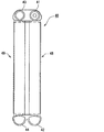
図1および図2に示すように、第1ヘッダ41と第2ヘッダ42とは、組をなしており、互いに所定距離れて平行に配置されている。第3ヘッダ43と第4ヘッダ44とも、組をなしており、互いに所定距離れて平行に配置されている。第1ヘッダ41と第2ヘッダ42との間には、複数の冷媒管45が等間隔に配列されている。第3ヘッダ43と第4ヘッダ44との間には、複数の冷媒管45が等間隔に配列されている。各冷媒管45は、その端部において対応するヘッダ内に連通している。
As shown in FIGS. 1 and 2, the
図2に示すように、これら第1ヘッダ41と、第2ヘッダ42と、それらの間に配置された複数の冷媒管45によって第1熱交換部48が形成されている。同様に、第3ヘッダ43と、第4ヘッダ44と、それらの間に配置された複数の冷媒管45によって第2熱交換部49が形成されている。この結果、蒸発器40は、2層に配置された第1熱交換部48と第2熱交換部49とを有する。空気の流れ方向に関して、第2熱交換部49が上流側に配置され、第1熱交換部48が下流側に配置されている。
As shown in FIG. 2, the first
第1ヘッダ41の端部には、冷媒入口としてのジョイント(図示せず)が設けられている。第1ヘッダ41内は、その長さ方向のほぼ中央に設けられた仕切板(図示せず)によって、第1区画と第2区画とに区画されている。これに対応して、複数の冷媒管45は、第1群と第2群とに区分されている。冷媒は、第1ヘッダ41の第1区画に供給される。冷媒は、第1区画から、第1群に属する複数の冷媒管45に分配される。冷媒は、第1群を通して第2ヘッダ42に流入し、集合される。冷媒は、第2ヘッダ42から、第2群に属する複数の冷媒管45に再び分配される。冷媒は、第2群を通して第1ヘッダ41の第2区画に流入する。このように、第1熱交換部48においては、冷媒をU字状に流す流路が形成される。
A joint (not shown) as a refrigerant inlet is provided at the end of the
第3ヘッダ43の端部には、冷媒出口としてのジョイント(図示せず)が設けられている。第3ヘッダ43内は、その長さ方向のほぼ中央に設けられた仕切板(図示せず)によって、第1区画と第2区画とに区画されている。これに対応して、複数の冷媒管45は、第1群と第2群とに区分されている。第3ヘッダ43の第1区画は、第1ヘッダ41の第2区画に隣接している。第3ヘッダ43の第1区画と第1ヘッダ41の第2区画とは連通している。
A joint (not shown) as a refrigerant outlet is provided at the end of the
冷媒は、第1ヘッダ41の第2区画から、第3ヘッダ43の第1区画に流入する。冷媒は、第1区画から、第1群に属する複数の冷媒管45に分配される。冷媒は、第1群を通して第4ヘッダ44に流入し、集合される。冷媒は、第4ヘッダ44から、第2群に属する複数の冷媒管45に再び分配される。冷媒は、第2群を通して第3ヘッダ43の第2区画に流入する。このように、第2熱交換部49においては、冷媒をU字状に流す流路が形成される。第3ヘッダ43の第2区画内の冷媒は、冷媒出口から流出し、圧縮機へ向けて流れる。
The refrigerant flows from the second section of the
次に、冷媒管45などの具体的な構成に関して説明する。図3では、蓄冷容器47の厚みは省略して示し、蓄冷材50にハッチングを施して示す。冷媒管45は、内部に冷媒が流通する複数の冷媒通路45aを有する多穴管である。冷媒管45は、扁平管とも呼ばれる。この多穴管は、押出製法によって得ることができる。複数の冷媒通路45aは、冷媒管45の長手方向に沿って延びており、冷媒管45の両端に開口している。複数の冷媒管45は、列をなして並べられている。各列において、複数の冷媒管45は、その主面が対向するように配置されている。複数の冷媒管45は、互いに隣接する2つの冷媒管45の間に、空気と熱交換するための空気通路460と、後述する蓄冷容器47を収容するための収容部461とを区画している。
Next, a specific configuration of the
蒸発器40は、車室へ供給される空気と接触面積を増加させるためのアウターフィン46を備える。アウターフィン46は、複数のコルゲート型のアウターフィン46によって提供されている。アウターフィン46は、隣接する2つの冷媒管45の間に区画された空気通路460に配置されている。アウターフィン46は、隣接する2つの冷媒管45と熱的に結合している。アウターフィン46は、熱伝達に優れた接合材によって、隣接する2つの冷媒管45に接合されている。接合材としては、ろう材を用いることができる。アウターフィン46は、薄いアルミニウム等の金属板が波状に曲げられた形状をもっており、ルーバーと呼ばれる空気通路460を備える。
The
次に、蓄冷容器47に関して説明する。蓄冷容器47は、蓄冷体であって、内部に蓄冷材50を収容するための部屋を区画している。蓄冷容器47は、扁平な筒状である。蓄冷容器47は、その長手方向両端において、筒をその厚さ方向に押しつぶすことによって閉じられ、内部に蓄冷材50を収容するための空間が形成される。蓄冷容器47は、広い主面を両面に有している。これら2つの主面を提供する2つの主壁は、それぞれが冷媒管45と平行に配置されている。そして少なくとも片面、本実施形態では両面に、冷媒管45が接触するように配置されている。
Next, the
蓄冷容器47は、その両側に配置された2つの冷媒管45に熱的に結合している。蓄冷容器47は、熱伝達に優れた接合材によって、隣接する2つの冷媒管45に接合されている。接合材としては、ろう材または接着剤などの樹脂材料を用いることができる。蓄冷容器47は、冷媒管45にろう付けされている。蓄冷容器47と冷媒管45との間には、それらの間を広い断面積によって連結するために大量のろう材が配置されている。このろう材は、蓄冷容器47と冷媒管45との間にろう材の箔を配置することによって提供することができる。この結果、蓄冷容器47は、冷媒管45との間で良好な熱伝導を示す。
The
各蓄冷容器47の厚さは、空気通路460の厚さとほぼ等しい。よって、蓄冷容器47の厚さは、アウターフィン46の厚さとほぼ等しい。アウターフィン46と蓄冷容器47とは、入れ替え可能である。この結果、複数のアウターフィン46と複数の蓄冷容器47との配置パターンを、高い自由度をもって設定することができる。
The thickness of each
蓄冷容器47の長さは、アウターフィン46とほぼ同じ長さを有する。この結果、蓄冷容器47は、隣接する2つの冷媒管45の間に区画された収容部461の長手方向のほぼ全体を占めている。また蓄冷容器47とヘッダ41〜44との間の隙間は、アウターフィン46の切片、あるいは樹脂などの充填材によって埋めることが望ましい。
The length of the
複数の冷媒管45は、ほぼ一定の間隔で配置されている。それら複数の冷媒管45の間には、複数の隙間が形成されている。これら複数の隙間には、複数のアウターフィン46と複数の蓄冷容器47とが、所定の規則性をもって配置されている。隙間のうちの一部は、空気通路460である。隙間のうちの残部は、蓄冷容器47の収容部461である。複数の冷媒管45の間に形成された合計間隔のうち、たとえば10%以上50%以下が収容部461とされる。収容部461には、蓄冷容器47が配置されている。
The plurality of
蓄冷容器47は、蒸発器40の全体にほぼ均等に分散して配置されている。蓄冷容器47の両側に位置する2つの冷媒管45は、蓄冷容器47とは反対側において空気と熱交換するための空気通路460を区画している。別の観点では、2つのアウターフィン46の間に2つの冷媒管45が配置され、さらにこれら2つの冷媒管45の間に2つの蓄冷容器47を1組とした蓄冷容器47が1組配置されている。
The
蓄冷容器47は、アルミニウムおよびアルミニウム合金等の金属製である。また蓄冷容器47のアルミニウム以外の材料としては、たとえばイオン化傾向が水素よりも低い金属を主材、もしくは成分として含む材料が用いられる。
The
次に、蓄冷材50に関して説明する。蓄冷材50は、冷媒通路45aを流通する冷媒と熱交換して冷媒からの熱量を留める材料である。蓄冷材50は、冷媒からの熱を凝固することで留め、留めた熱を融解することによって外部に放出する。
Next, the
本実施形態の蓄冷材50は、炭素数の異なる2種類以上のエステル化合物が混合された材料を含む。比較例として、2種類のアルキル基でエステル結合をはさんだ分子構造を持つエステル化合物では、融解潜熱が高く車両用熱交換器への適用可能性がある。しかし融点が0℃以下や、15℃以上であるものが大半をしめ、車両用空調装置の運転温度範囲外のため蓄冷することができない。さらにエステル結合の中に2重結合を含むためパラフィンに比べて酸化劣化しやすいという2つの課題がある。
The
車両用空調装置は運転中に凝縮水が凝固し蒸発器40中の空気流れを閉塞することによる性能低下を防止するため、冷媒が0℃以下にならないようにする。そのため、0℃以下に融点を持つ2つのアルキル基がともに炭素数2以上のエステル化合物は使用できず、アルキル基の1つの炭素数が1(=メチル基)である必要がある。
The vehicle air conditioner prevents the refrigerant from becoming below 0 ° C. in order to prevent performance degradation due to condensation of condensed water during operation and blocking the air flow in the
そこで本実施形態のエステル化合物は、炭素数が10以上40以下であり、アルキル基とメチル基とで挟まれた1つのエステル結合(二重結合)から構成される。エステル化合物は、R1−CO−O−R2である。ここでR1は、たとえばCH3〜C18C37である。またR2は、たとえばC8H17〜C22H45である。 Therefore, the ester compound of the present embodiment has 10 to 40 carbon atoms and is composed of one ester bond (double bond) sandwiched between an alkyl group and a methyl group. The ester compound is R1-CO-O-R2. Here, R1 is, for example, CH 3 to C 18 C 37 . R2 is, for example, C 8 H 17 to C 22 H 45 .
また、冷房感を維持するため融点も低温なものを選択するのが好ましい。たとえば、表1のようにR1が炭素数1、R2が炭素数12のエステル化合物A(第1のエステル化合物)と、R1が炭素数1、R2が炭素数14のエステル化合物B(第2のエステル化合物)の混合物を蓄冷材50として使用するのが好ましい。エステル化合物Aは、炭素数が14である。またエステル化合物Bは、炭素数が16である。
In order to maintain a cooling feeling, it is preferable to select one having a low melting point. For example, as shown in Table 1, R1 is C1 and R2 is C12 ester compound A (first ester compound), and R1 is C1 and R2 is C14 ester compound B (second It is preferable to use a mixture of ester compounds) as the
換言すると、蓄冷材50は、エステル結合を2つのアルキル基(炭素と水素からなる官能基)ではさんだ構造をもつ2つのエステル化合物を基材としている。そしてエステル化合物Aは、単体の融点が5℃の2つのアルキル基が炭素数1のメチル基と炭素数12のアルキル基である。またエステル化合物Bは、単体の融点が18℃の2つアルキル基が炭素数1のメチル基と炭素数14のアルキル基である。

さらに、配合比としては、エステル化合物Aを蓄冷材50における質量パーセント濃度が5質量パーセント濃度以上、20質量パーセント濃度以下、エステル化合物Bを80質量パーセント濃度以上、95質量パーセント濃度以下にするのがさらに好ましい。表1のナンバー2〜4が、好ましい組み合わせに該当する。この配合比にすることで、高い潜熱を確保しつつ、融点を冷房の維持に必要な温度にすることができる。また表1のナンバー6にあるように、ナンバー2〜4の蓄冷材50は、パラフィンと同等の潜熱(=体積あたり)の蓄冷熱量をもつ。したがって蓄冷容器47の大型化を抑制することができる。
Furthermore, as a compounding ratio, the mass percentage concentration of the ester compound A in the
さらに蒸発器40は、材料としてアルミニウムを用いる場合、水分と接触することでアルミニウムが腐食することによる容器の穴あき、腐食反応での生成物である水素ガスで容器内が加圧され容器の膨張および変形するおそれがある。そこで蓄冷材50に水素発生防止剤を添加することが好ましい。水素発生抑制剤は、たとえばアミン塩、カルボン酸エステル、ベンゾトリアゾール、スルホン酸塩、リン酸エステルおよびこれらの混合物からなる群からなる少なくとも1種類から選択するのが好ましい。
Further, when the
またエステル化合物はエステル結合中に炭素と酸素原子で2重結合を構成しており、酸化劣化しやすい。そこで蓄冷材50に、酸化防止剤も添加するのが好ましい。酸化防止剤として、たとえばフェノール系酸化防止剤が用いられる。
Further, the ester compound forms a double bond with carbon and oxygen atoms in the ester bond, and is easily oxidized and deteriorated. Therefore, it is preferable to add an antioxidant to the
次に、本実施形態の作動を説明する。乗員からの空調要求、例えば冷房要求があると、圧縮機は動力源によって駆動される。圧縮機は蒸発器40から冷媒を吸入し、圧縮して、吐出する。圧縮機から吐出された冷媒は、放熱器で放熱される。放熱器から出た冷媒は、減圧器によって減圧され、蒸発器40に供給される。冷媒は、蒸発器40において蒸発し、蓄冷容器47を冷却するとともに、アウターフィン46を介して周囲の空気を冷却する。車両が一時停止すると、動力源は消費エネルギを減らすために停止し、圧縮機が停止する。その後、蒸発器40の冷媒は徐々に冷却能力を失ってゆく。この過程で、蓄冷材50は、徐々に放冷し、空気を冷却する。このとき、空気の熱は、アウターフィン46、冷媒管45、および蓄冷容器47を通して、蓄冷材50に伝導する。この結果、冷凍サイクル装置が一時的に停止しても、蓄冷材50によって空気を冷却することができる。やがて、車両が再び走行を始めると、動力源が再び圧縮機を駆動する。このため、冷凍サイクル装置は、再び蓄冷材50を冷却し、蓄冷材50が蓄冷する。
Next, the operation of this embodiment will be described. When there is an air conditioning request from the passenger, for example, a cooling request, the compressor is driven by a power source. The compressor sucks the refrigerant from the
以上説明したように本実施形態の蓄冷材50は、炭素数の異なる2種類以上のエステル化合物が混合された材料を含む。そしてエステル化合物は、炭素数が10以上40以下であり、アルキル基とメチル基とで挟まれた1つのエステル結合から構成される。2つのアルキル基で挟まれた1つのエステル結合であると、融点が0℃以下になるが、前述のようにメチル基を用いることによって融点を0℃よりも高くすることができる。したがって蓄冷材50の凝固および融解する温度範囲を適切な範囲で広くすることができる。これによって空気の温度が低い場合であっても、蓄冷材50は融解して放冷することができる。したがって空気の温度が低い場合であっても、通過する空気の湿球温度以下に維持することが可能となり、凝縮水の蒸発に伴う臭いの発生を抑制することができる。また蓄冷材50が蓄冷および放冷できる温度範囲が広いので、より広範囲な空気温度において蓄冷機能を維持することができる。
As described above, the
換言すると、本実施形態の蓄冷材50は、広い温度範囲で蓄冷することができる。これにより、従来技術のように夏季だけでなく冬季(10℃以下環境)でもアイドルストップ時間を確保することができる。
In other words, the
また本実施形態では、エステル化合物は、炭素数が14以上18以下であるので、表1に示すように、潜熱をパラフィンと同等にすることができる。これによって融点が広い温度範囲で潜熱を蓄冷できる蓄冷材50を実現することができる。
In this embodiment, since the ester compound has 14 to 18 carbon atoms, the latent heat can be equivalent to that of paraffin as shown in Table 1. Thus, it is possible to realize the
(第2実施形態)
次に、本発明の第2実施形態に関して、図4を用いて説明する。本実施形態では、蓄冷容器47Bの配置に特徴を有する。蓄冷容器47Bは、隣接する2つの冷媒管45の間に複数、本実施形態では2つ配置されている。各蓄冷容器47Bは、吸込み空気の流れ方向に沿って配列されている。また同一の収容部461においては、各蓄冷容器47Bは、それぞれ異なる蓄冷材50a,50bを収容している。
(Second Embodiment)
Next, a second embodiment of the present invention will be described with reference to FIG. This embodiment is characterized by the arrangement of the
各蓄冷材50a,50bは、たとえば表1のナンバー2〜4のうち、互いに異なる2つが選択される。これによって1種類の蓄冷材50を用いるよりもさらに広い温度範囲で蓄冷できるようになる。
For each of the
(第3実施形態)
次に、本発明の第3実施形態に関して、図5を用いて説明する。本実施形態では、蓄冷容器47Cの配置に特徴を有する。蓄冷容器47Cは、隣接する2つの冷媒管45の間に複数、本実施形態では2つ配置されている。各蓄冷容器47Cは、吸込み空気の流れ方向に直行する方向に沿って配列されている。換言すると、各蓄冷容器47Cは、冷媒管45が間隔をあけて配置されている方向に積層されている。また同一の収容部461においては、各蓄冷容器47Cは、それぞれ異なる蓄冷材50a,50bを収容している。
(Third embodiment)
Next, a third embodiment of the present invention will be described with reference to FIG. This embodiment is characterized by the arrangement of the
各蓄冷材50a,50bは、たとえば表1のナンバー2〜4のうち、互いに異なる2つが選択される。これによって1種類の蓄冷材50を用いるよりもさらに広い温度範囲で蓄冷できるようになる。
For each of the
(その他の実施形態)
以上、本発明の好ましい実施形態について説明したが、本発明は上述した実施形態に何ら制限されることなく、本発明の主旨を逸脱しない範囲において種々変形して実施することが可能である。
(Other embodiments)
The preferred embodiments of the present invention have been described above, but the present invention is not limited to the above-described embodiments, and various modifications can be made without departing from the spirit of the present invention.
上記実施形態の構造は、あくまで例示であって、本発明の範囲はこれらの記載の範囲に限定されるものではない。本発明の範囲は、特許請求の範囲の記載によって示され、さらに特許請求の範囲の記載と均等の意味及び範囲内での全ての変更を含むものである。 The structure of the said embodiment is an illustration to the last, Comprising: The scope of the present invention is not limited to the range of these description. The scope of the present invention is indicated by the description of the scope of claims, and further includes meanings equivalent to the description of the scope of claims and all modifications within the scope.
前述の第1実施形態では、各蓄冷容器47に封入される蓄冷材50は、互いに等しいが、互いに等しい構成に限るものではない。たとえば隣接する蓄冷容器47においては、前述の第2実施形態および第3実施形態のように、互いに異なる蓄冷材50を封入してもよい。これによっても第2実施形態および第3実施形態と同様の作用および効果を達成することができる。
In the first embodiment described above, the
また前述の第1実施形態では、蓄冷体は蓄冷容器47によって実現されているが、内部に蓄冷材50のみを収容している蓄冷容器47に限るものではない。したがって蓄冷体は、たとえば複数の部材を組み合わせて、内部に蓄冷材を収容する部屋を区画している部材であってもよい。換言すると、たとえば蓄冷体は1枚の板をS字状に変形させて、その開口を他の部材で多い、一方の空間を蓄冷材に収容し、他方の空間に冷媒などを収容してもよい。
In the first embodiment described above, the cool storage body is realized by the
冷媒管45は、多穴押出管、あるいはディンプルを形成した板材を筒状に曲げた管によって提供することができる。さらに、アウターフィン46は省略することができる。このような熱交換器は、フィンレス型とも呼ばれる。アウターフィン46に代えて、冷媒管から延び出す突条などを設けて、空気との熱交換を促進してもよい。
The
本発明は、種々の流れ経路をもつ蒸発器に適用することができる。例えば、第1実施形態のような左右Uターン型に代えて、一方向型、前後Uターン型などの蒸発器に本発明を適用してもよい。 The present invention can be applied to an evaporator having various flow paths. For example, instead of the left and right U-turn type as in the first embodiment, the present invention may be applied to an evaporator such as a one-way type or a front and rear U-turn type.
さらに、本発明は、冷凍用、暖房用、給湯用といった冷凍サイクル装置に適用されてもよい。さらに、本発明は、エジェクタを備える冷凍サイクル装置に適用されてもよい。 Furthermore, the present invention may be applied to refrigeration cycle apparatuses such as refrigeration, heating, and hot water supply. Furthermore, the present invention may be applied to a refrigeration cycle apparatus including an ejector.
40…蒸発器(蓄冷熱交換器) 41…第1ヘッダ
42…第2ヘッダ 43…第3ヘッダ
44…第4ヘッダ 45…冷媒管
45a…冷媒通路 46…アウターフィン
47…蓄冷容器(蓄冷体) 48…第1熱交換部
49…第2熱交換部 50,50a,50b…蓄冷材
70…インナーフィン 460…空気通路
461…収容部
DESCRIPTION OF
Claims (3)
内部に冷媒が流通する冷媒通路(45a)と、
前記冷媒通路を流通する前記冷媒と熱交換して前記冷媒からの熱量を留める蓄冷材(50,50a,50b)を内部に収容する蓄冷体(47)と、を含み、
前記蓄冷材は、炭素数の異なる2種類以上のエステル化合物が混合された材料を含み、
前記エステル化合物は、炭素数が10以上40以下であり、アルキル基とメチル基とで挟まれた1つのエステル結合から構成されることを特徴とする蓄冷熱交換器。 A regenerative heat exchanger (40) for exchanging heat with air flowing around it,
A refrigerant passage (45a) through which the refrigerant flows;
A regenerator (47) that houses therein a regenerator material (50, 50a, 50b) that exchanges heat with the refrigerant flowing through the refrigerant passage and retains the amount of heat from the refrigerant,
The regenerator material includes a material in which two or more ester compounds having different carbon numbers are mixed,
The said ester compound is C10 or more and 40 or less, and is comprised from one ester bond pinched | interposed by the alkyl group and the methyl group, The cool storage heat exchanger characterized by the above-mentioned.
前記第1のエステル化合物は、前記蓄冷材における質量パーセント濃度が5質量パーセント濃度以上、20質量パーセント濃度以下であり、
前記第2のエステル化合物は、前記蓄冷材における質量パーセント濃度が80質量パーセント濃度以上、95質量パーセント濃度以下であることを特徴とする請求項2に記載の蓄冷熱交換器。 The cold storage material includes a material in which a first ester compound having 14 carbon atoms and a second ester compound having 16 carbon atoms are mixed,
The first ester compound has a mass percent concentration in the cold storage material of 5 mass percent concentration or more and 20 mass percent concentration or less,
The cold storage heat exchanger according to claim 2, wherein the second ester compound has a mass percent concentration in the cold storage material of not less than 80 mass percent and not more than 95 mass percent.
Priority Applications (1)
| Application Number | Priority Date | Filing Date | Title |
|---|---|---|---|
| JP2014009869A JP6206209B2 (en) | 2014-01-22 | 2014-01-22 | Cold storage heat exchanger |
Applications Claiming Priority (1)
| Application Number | Priority Date | Filing Date | Title |
|---|---|---|---|
| JP2014009869A JP6206209B2 (en) | 2014-01-22 | 2014-01-22 | Cold storage heat exchanger |
Publications (2)
| Publication Number | Publication Date |
|---|---|
| JP2015137807A true JP2015137807A (en) | 2015-07-30 |
| JP6206209B2 JP6206209B2 (en) | 2017-10-04 |
Family
ID=53768920
Family Applications (1)
| Application Number | Title | Priority Date | Filing Date |
|---|---|---|---|
| JP2014009869A Expired - Fee Related JP6206209B2 (en) | 2014-01-22 | 2014-01-22 | Cold storage heat exchanger |
Country Status (1)
| Country | Link |
|---|---|
| JP (1) | JP6206209B2 (en) |
Cited By (2)
| Publication number | Priority date | Publication date | Assignee | Title |
|---|---|---|---|---|
| WO2017199554A1 (en) * | 2016-05-19 | 2017-11-23 | 株式会社デンソー | Cold storage evaporator and vehicle refrigeration cycle device provided with same |
| JPWO2021025134A1 (en) * | 2019-08-07 | 2021-02-11 |
Citations (4)
| Publication number | Priority date | Publication date | Assignee | Title |
|---|---|---|---|---|
| JP2005054064A (en) * | 2003-08-05 | 2005-03-03 | Osaka Gas Co Ltd | Solid heat storage material |
| JP2005255726A (en) * | 2004-03-09 | 2005-09-22 | Sumitomo Rubber Ind Ltd | Cold and heat insulating materials using gel, and pillows, foot warmers and face masks using the same |
| JP2006233176A (en) * | 2005-01-27 | 2006-09-07 | Sk Kaken Co Ltd | Manufacturing method of heat storage body |
| WO2013186983A1 (en) * | 2012-06-14 | 2013-12-19 | 株式会社デンソー | Cold storage heat exchanger |
-
2014
- 2014-01-22 JP JP2014009869A patent/JP6206209B2/en not_active Expired - Fee Related
Patent Citations (4)
| Publication number | Priority date | Publication date | Assignee | Title |
|---|---|---|---|---|
| JP2005054064A (en) * | 2003-08-05 | 2005-03-03 | Osaka Gas Co Ltd | Solid heat storage material |
| JP2005255726A (en) * | 2004-03-09 | 2005-09-22 | Sumitomo Rubber Ind Ltd | Cold and heat insulating materials using gel, and pillows, foot warmers and face masks using the same |
| JP2006233176A (en) * | 2005-01-27 | 2006-09-07 | Sk Kaken Co Ltd | Manufacturing method of heat storage body |
| WO2013186983A1 (en) * | 2012-06-14 | 2013-12-19 | 株式会社デンソー | Cold storage heat exchanger |
Cited By (8)
| Publication number | Priority date | Publication date | Assignee | Title |
|---|---|---|---|---|
| WO2017199554A1 (en) * | 2016-05-19 | 2017-11-23 | 株式会社デンソー | Cold storage evaporator and vehicle refrigeration cycle device provided with same |
| JPWO2017199554A1 (en) * | 2016-05-19 | 2018-09-13 | 株式会社デンソー | Cold storage evaporator and vehicular refrigeration cycle apparatus including the same |
| CN109153316A (en) * | 2016-05-19 | 2019-01-04 | 株式会社电装 | Cold-storage evaporator and vehicle refrigerating circulatory device with the cold-storage evaporator |
| US10976083B2 (en) | 2016-05-19 | 2021-04-13 | Denso Corporation | Cold energy storage evaporator and vehicle refrigeration cycle device provided with same |
| CN109153316B (en) * | 2016-05-19 | 2021-11-23 | 株式会社电装 | Cold storage evaporator and refrigeration cycle device for vehicle having the same |
| JPWO2021025134A1 (en) * | 2019-08-07 | 2021-02-11 | ||
| WO2021025134A1 (en) * | 2019-08-07 | 2021-02-11 | 国立大学法人東北大学 | Latent heat storage material composition, and method for controlling latent heat storage characteristics |
| JP7504475B2 (en) | 2019-08-07 | 2024-06-24 | 国立大学法人東北大学 | Latent heat storage material composition and method for controlling latent heat storage characteristics |
Also Published As
| Publication number | Publication date |
|---|---|
| JP6206209B2 (en) | 2017-10-04 |
Similar Documents
| Publication | Publication Date | Title |
|---|---|---|
| WO2013186983A1 (en) | Cold storage heat exchanger | |
| JP5910415B2 (en) | Cold storage heat exchanger | |
| JP6281394B2 (en) | Cold storage heat exchanger | |
| JP6623912B2 (en) | Evaporator | |
| JP5274175B2 (en) | Cold storage heat exchanger | |
| JP5276954B2 (en) | Evaporator with cool storage function | |
| JP5764335B2 (en) | Evaporator with cool storage function | |
| US10401062B2 (en) | Cold storage heat exchanger | |
| WO2010150774A1 (en) | Evaporator with cold storage function | |
| JP5920087B2 (en) | Cold storage heat exchanger | |
| JP6406116B2 (en) | Air conditioner for vehicles | |
| JP6206209B2 (en) | Cold storage heat exchanger | |
| JP2010139201A (en) | Cold storage device and vehicle air conditioner using the same | |
| JP2010243066A (en) | Cold storage heat exchanger | |
| US11073342B2 (en) | Regenerative heat exchanger | |
| JP2014034037A (en) | Cold storage heat exchanger and method of manufacturing the same | |
| JP2013200073A (en) | Evaporator with cooling storage function | |
| JP2013104580A (en) | Cold storage heat exchanger | |
| JP6327386B2 (en) | Cold storage heat exchanger | |
| WO2022044741A1 (en) | Cold-storage heat exchanger | |
| JP2014149097A (en) | Cold storage heat exchanger | |
| JP2019120412A (en) | Heat exchanger | |
| JP2017132427A (en) | Cold storage heat exchanger | |
| WO2018008298A1 (en) | Cold storage heat exchanger |
Legal Events
| Date | Code | Title | Description |
|---|---|---|---|
| A621 | Written request for application examination |
Free format text: JAPANESE INTERMEDIATE CODE: A621 Effective date: 20160325 |
|
| A977 | Report on retrieval |
Free format text: JAPANESE INTERMEDIATE CODE: A971007 Effective date: 20170124 |
|
| A131 | Notification of reasons for refusal |
Free format text: JAPANESE INTERMEDIATE CODE: A131 Effective date: 20170131 |
|
| A521 | Request for written amendment filed |
Free format text: JAPANESE INTERMEDIATE CODE: A523 Effective date: 20170315 |
|
| TRDD | Decision of grant or rejection written | ||
| A01 | Written decision to grant a patent or to grant a registration (utility model) |
Free format text: JAPANESE INTERMEDIATE CODE: A01 Effective date: 20170808 |
|
| A61 | First payment of annual fees (during grant procedure) |
Free format text: JAPANESE INTERMEDIATE CODE: A61 Effective date: 20170821 |
|
| R151 | Written notification of patent or utility model registration |
Ref document number: 6206209 Country of ref document: JP Free format text: JAPANESE INTERMEDIATE CODE: R151 |
|
| R250 | Receipt of annual fees |
Free format text: JAPANESE INTERMEDIATE CODE: R250 |
|
| R250 | Receipt of annual fees |
Free format text: JAPANESE INTERMEDIATE CODE: R250 |
|
| LAPS | Cancellation because of no payment of annual fees |