JP2015149189A - コネクタ端子 - Google Patents
コネクタ端子 Download PDFInfo
- Publication number
- JP2015149189A JP2015149189A JP2014021522A JP2014021522A JP2015149189A JP 2015149189 A JP2015149189 A JP 2015149189A JP 2014021522 A JP2014021522 A JP 2014021522A JP 2014021522 A JP2014021522 A JP 2014021522A JP 2015149189 A JP2015149189 A JP 2015149189A
- Authority
- JP
- Japan
- Prior art keywords
- sheath
- terminal
- elastic contact
- contact piece
- connector
- Prior art date
- Legal status (The legal status is an assumption and is not a legal conclusion. Google has not performed a legal analysis and makes no representation as to the accuracy of the status listed.)
- Granted
Links
Images







Classifications
-
- H—ELECTRICITY
- H01—ELECTRIC ELEMENTS
- H01R—ELECTRICALLY-CONDUCTIVE CONNECTIONS; STRUCTURAL ASSOCIATIONS OF A PLURALITY OF MUTUALLY-INSULATED ELECTRICAL CONNECTING ELEMENTS; COUPLING DEVICES; CURRENT COLLECTORS
- H01R13/00—Details of coupling devices of the kinds covered by groups H01R12/70 or H01R24/00 - H01R33/00
- H01R13/40—Securing contact members in or to a base or case; Insulating of contact members
- H01R13/42—Securing in a demountable manner
- H01R13/424—Securing in base or case composed of a plurality of insulating parts having at least one resilient insulating part
-
- H—ELECTRICITY
- H01—ELECTRIC ELEMENTS
- H01R—ELECTRICALLY-CONDUCTIVE CONNECTIONS; STRUCTURAL ASSOCIATIONS OF A PLURALITY OF MUTUALLY-INSULATED ELECTRICAL CONNECTING ELEMENTS; COUPLING DEVICES; CURRENT COLLECTORS
- H01R13/00—Details of coupling devices of the kinds covered by groups H01R12/70 or H01R24/00 - H01R33/00
- H01R13/02—Contact members
- H01R13/15—Pins, blades or sockets having separate spring member for producing or increasing contact pressure
- H01R13/187—Pins, blades or sockets having separate spring member for producing or increasing contact pressure with spring member in the socket
-
- H—ELECTRICITY
- H01—ELECTRIC ELEMENTS
- H01R—ELECTRICALLY-CONDUCTIVE CONNECTIONS; STRUCTURAL ASSOCIATIONS OF A PLURALITY OF MUTUALLY-INSULATED ELECTRICAL CONNECTING ELEMENTS; COUPLING DEVICES; CURRENT COLLECTORS
- H01R13/00—Details of coupling devices of the kinds covered by groups H01R12/70 or H01R24/00 - H01R33/00
- H01R13/62—Means for facilitating engagement or disengagement of coupling parts or for holding them in engagement
- H01R13/629—Additional means for facilitating engagement or disengagement of coupling parts, e.g. aligning or guiding means, levers, gas pressure electrical locking indicators, manufacturing tolerances
-
- H—ELECTRICITY
- H01—ELECTRIC ELEMENTS
- H01R—ELECTRICALLY-CONDUCTIVE CONNECTIONS; STRUCTURAL ASSOCIATIONS OF A PLURALITY OF MUTUALLY-INSULATED ELECTRICAL CONNECTING ELEMENTS; COUPLING DEVICES; CURRENT COLLECTORS
- H01R24/00—Two-part coupling devices, or either of their cooperating parts, characterised by their overall structure
- H01R24/76—Two-part coupling devices, or either of their cooperating parts, characterised by their overall structure with sockets, clips or analogous contacts and secured to apparatus or structure, e.g. to a wall
-
- H—ELECTRICITY
- H01—ELECTRIC ELEMENTS
- H01R—ELECTRICALLY-CONDUCTIVE CONNECTIONS; STRUCTURAL ASSOCIATIONS OF A PLURALITY OF MUTUALLY-INSULATED ELECTRICAL CONNECTING ELEMENTS; COUPLING DEVICES; CURRENT COLLECTORS
- H01R4/00—Electrically-conductive connections between two or more conductive members in direct contact, i.e. touching one another; Means for effecting or maintaining such contact; Electrically-conductive connections having two or more spaced connecting locations for conductors and using contact members penetrating insulation
- H01R4/10—Electrically-conductive connections between two or more conductive members in direct contact, i.e. touching one another; Means for effecting or maintaining such contact; Electrically-conductive connections having two or more spaced connecting locations for conductors and using contact members penetrating insulation effected solely by twisting, wrapping, bending, crimping, or other permanent deformation
- H01R4/18—Electrically-conductive connections between two or more conductive members in direct contact, i.e. touching one another; Means for effecting or maintaining such contact; Electrically-conductive connections having two or more spaced connecting locations for conductors and using contact members penetrating insulation effected solely by twisting, wrapping, bending, crimping, or other permanent deformation by crimping
- H01R4/183—Electrically-conductive connections between two or more conductive members in direct contact, i.e. touching one another; Means for effecting or maintaining such contact; Electrically-conductive connections having two or more spaced connecting locations for conductors and using contact members penetrating insulation effected solely by twisting, wrapping, bending, crimping, or other permanent deformation by crimping for cylindrical elongated bodies, e.g. cables having circular cross-section
- H01R4/184—Electrically-conductive connections between two or more conductive members in direct contact, i.e. touching one another; Means for effecting or maintaining such contact; Electrically-conductive connections having two or more spaced connecting locations for conductors and using contact members penetrating insulation effected solely by twisting, wrapping, bending, crimping, or other permanent deformation by crimping for cylindrical elongated bodies, e.g. cables having circular cross-section comprising a U-shaped wire-receiving portion
- H01R4/185—Electrically-conductive connections between two or more conductive members in direct contact, i.e. touching one another; Means for effecting or maintaining such contact; Electrically-conductive connections having two or more spaced connecting locations for conductors and using contact members penetrating insulation effected solely by twisting, wrapping, bending, crimping, or other permanent deformation by crimping for cylindrical elongated bodies, e.g. cables having circular cross-section comprising a U-shaped wire-receiving portion combined with a U-shaped insulation-receiving portion
-
- H—ELECTRICITY
- H01—ELECTRIC ELEMENTS
- H01R—ELECTRICALLY-CONDUCTIVE CONNECTIONS; STRUCTURAL ASSOCIATIONS OF A PLURALITY OF MUTUALLY-INSULATED ELECTRICAL CONNECTING ELEMENTS; COUPLING DEVICES; CURRENT COLLECTORS
- H01R13/00—Details of coupling devices of the kinds covered by groups H01R12/70 or H01R24/00 - H01R33/00
- H01R13/02—Contact members
- H01R13/10—Sockets for co-operation with pins or blades
- H01R13/11—Resilient sockets
- H01R13/113—Resilient sockets co-operating with pins or blades having a rectangular transverse section
Landscapes
- Connector Housings Or Holding Contact Members (AREA)
- Details Of Connecting Devices For Male And Female Coupling (AREA)
Abstract
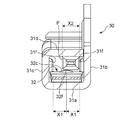
【解決手段】コネクタ端子30は、電気コネクタのハウジングの端子収容室に挿入される鞘状部31と、鞘状部31に設けられ、接続相手の電気コネクタの雄端子と接触する弾性接触片32とを備えている。鞘状部31には、弾性接触片32の先端部32dの突起部31fが形成されている。この突起部31fは、鞘状部31の側壁31b,31cに外側から凹部31gを形成することで内側に突出させて形成したものである。
【選択図】図5
Description
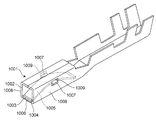
このため、特許文献1に記載の雌端子は、電気接触部1001の開口部から雄端子を挿入した際に、弾性接触板1005が雄端子の挿入方向に移動せず、弾性接触板1005に設けた耳片1007が電気接触部1001の側壁1008に設けた係合用窓穴1009の口縁に強く当接することはない。従って、特許文献1に記載の雌端子は、弾性接触板1005の弾発作用を阻害しないから、雄端子の挿入時に強い挿入力を不要とすることができるというものである。
この特許文献2に記載の電気接続子では、係止溝1104の下縁に一致するように、電気接触部1101内に係止段部1105を一体に設けていため、係止段部1105が板バネ1102の耳片1103を支持し、最終突き合わせ工程で、耳片1103は係止溝1104上の下縁にも載置されて、正規位置に保持されるというものである。
弾性接触板1005(弾性接触片)が浮き上がり、雄端子の挿入方向の正面に弾性接触片の先端面が位置してしまうと、雄端子が弾性接触片の先端面を挿入方向に押圧することで、弾性接触片が折れ曲がってしまうおそれがある。
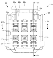
電気コネクタ10は、モールド成形により形成されたハウジング20と、接続相手となる雄側の電気コネクタCの雄端子Pが挿入される雌型のコネクタ端子30とを備えている。
ハウジング本体21は、外形が直方体状に形成され、前後方向に沿って端子収容室21a(図4参照)が上下2段に相互に対向して3つずつ形成されている。
また、図1,図2および図4に示すように、ハウジング本体21の前面21bには、引き抜き治具を挿入するための引き抜き治具用の挿入口21fが形成されている。
前端部22aは、解除操作部22cが押し下げられると弾性変形する。アーム本体22bには、雄側の電気コネクタCのハウジングHに係止してロック状態とするためのロック用爪部22eが形成されている。解除操作部22cは、アーム本体22bの中途部から後端部22d上方へ向かって延設されて形成されている。
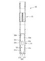
鞘状部31、弾性接触片32および結束部33などは、導電性の良好な金属板を曲げ加工することにより、一体的に形成されている。ただし、本発明の実施形態に係る電気コネクタにおいて、弾性接触片32は鞘状部31と別体の部品で構成されている。
鞘状部31の一方の側壁31bには、ハウジング20への上下逆挿入を防止すると共に、コネクタ端子30をハウジング20へ挿入した後の姿勢を安定させるためのスタビライザ31eが、起立した状態で突出している。
また、鞘状部31の両方の側壁31b,31cには、弾性接触片32の耳部32bが嵌る切り欠き部31hが形成されている。
弾性接触片32は、先端部32dと後端部32eとが鞘状部31の床面31aに支持され、中央部に位置する耳部32bが鞘状部31の両方の側壁31b,31cに形成された切り欠き部31hに嵌り、天井面31d側への変位が抑止されることで、先端部32dと後端部32eとが自由端であっても弓型の板ばねとして機能している。
凸部32cは、板ばね部32aの接触面とは反対側となる裏面から打ち出すことで膨出した円弧面により形成されている。
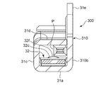
例えば、図12に示すように、コネクタ端子300の鞘状部310に突起部が形成されていない場合には、雄端子Pが鞘状部310の中心から外れ、一方の側壁310b側に片寄って挿入されるときがある。
そうなると、雄端子Pは、その中心軸が弾性接触片32の凸部32cの頂上部32fから外れるため、安定性が悪く、接触する面積が減少するので、接触不良となりやすい。
引き抜き治具によりコネクタ端子30を引き抜くときには、ハウジング20の前面21bに形成された引き抜き治具用の挿入口21f(図1および図3参照)に、引き抜き治具を挿入する。
そのため、作業者が誤って、引き抜き治具を嵌合用の挿入口21cへ挿入しても、引き抜き治具が突起部31fに当接して、引き抜き治具の挿入が阻止される。
また、引き抜き治具の幅が、鞘状部31の開口幅L1より狭くても、突起部31f同士の間隔L2より広ければ、引き抜き治具が突起部31fに当接して、引き抜き治具の挿入を阻止することができる。
従って、コネクタ端子30は、引き抜き治具の誤挿入により、弾性接触片32を傷付けたり、破損させたりすることを防止することができる。
20 ハウジング
21 ハウジング本体
21a 端子収容室
21b 前面
21c 挿入口
21d 案内部
21e 連絡部
21f 挿入口
21g 天面
21h ランス部
21j 抜け止め部
22 ロックアーム
22a 前端部
22b アーム本体
22c 解除操作部
22d 後端部
22e ロック用爪部
30 コネクタ端子
31 鞘状部
31a 床面
31b,31c 側壁
31d 天井面
31e スタビライザ
31f 突起部
31g 凹部
31h 切り欠き部
31j 凹部
32 弾性接触片
32a 板ばね部
32b 耳部
32c 凸部
32d 先端部
32e 後端部
32f 頂上部
33 結束部
C 雄側の電気コネクタ
H ハウジング
P 雄端子
100 従来の電気コネクタ
300 コネクタ端子
310 鞘状部
310b 側壁
L1,L3 開口幅
L2 間隔
Claims (5)
- 電気コネクタのハウジングの端子収容室に挿入される鞘状部と、
前記鞘状部に設けられ、接続相手の電気コネクタの雄端子と接触する弾性接触片とを備え、
前記雄端子が挿入されるハウジングの挿入口の範囲内に、前記弾性接触片の先端部が変位することを防止する突起部が、前記鞘状部に形成されたコネクタ端子。 - 前記突起部が、前記鞘状部の側壁に外側から凹部を形成することで内側に突出させたものである請求項1記載のコネクタ端子。
- 前記突起部が、前記鞘状部の両方の側壁に一対形成されたものである請求項1または2記載のコネクタ端子。
- 前記弾性接触片に、前記雄端子と接触する凸部が形成され、
前記突起部から前記凸部の頂上部までの距離が、前記雄端子の幅より短い請求項1記載のコネクタ端子。 - 前記鞘状部の開口幅が、
前記端子収容室に挿入されて抜け止め部により係止した状態の前記鞘状部を、係止状態を解除して引き抜くための引き抜き治具挿入口の幅より、前記突起部によって狭くなった請求項1記載のコネクタ端子。
Priority Applications (12)
| Application Number | Priority Date | Filing Date | Title |
|---|---|---|---|
| JP2014021522A JP5708837B1 (ja) | 2014-02-06 | 2014-02-06 | コネクタ端子 |
| DE102015200058.3A DE102015200058A1 (de) | 2014-01-10 | 2015-01-07 | Verriegelungsarm und elektrischer verbinder, der diesen umfasst |
| FR1550138A FR3016483B1 (fr) | 2014-01-10 | 2015-01-08 | Bras de blocage et connecteur electrique comprenant celui-ci |
| CN201510013078.1A CN104779481B (zh) | 2014-01-10 | 2015-01-09 | 锁定臂和电连接器 |
| US14/594,657 US9312635B2 (en) | 2014-01-10 | 2015-01-12 | Lock arm and electric connector including the same |
| US14/602,029 US9190758B2 (en) | 2014-02-06 | 2015-01-21 | Connector terminal |
| US14/606,760 US9318836B2 (en) | 2014-02-06 | 2015-01-27 | Electric connector |
| DE102015201726.5A DE102015201726A1 (de) | 2014-02-06 | 2015-02-02 | Elektrischer Verbinder |
| DE102015201818.0A DE102015201818A1 (de) | 2014-02-06 | 2015-02-03 | Verbinderanschluss |
| CN201510061017.2A CN104836046B (zh) | 2014-02-06 | 2015-02-05 | 连接器端子 |
| FR1550909A FR3017251B1 (fr) | 2014-02-06 | 2015-02-05 | Borne de connecteur |
| FR1550911A FR3017253B1 (fr) | 2014-02-06 | 2015-02-05 | Connecteur electrique |
Applications Claiming Priority (1)
| Application Number | Priority Date | Filing Date | Title |
|---|---|---|---|
| JP2014021522A JP5708837B1 (ja) | 2014-02-06 | 2014-02-06 | コネクタ端子 |
Publications (2)
| Publication Number | Publication Date |
|---|---|
| JP5708837B1 JP5708837B1 (ja) | 2015-04-30 |
| JP2015149189A true JP2015149189A (ja) | 2015-08-20 |
Family
ID=53277146
Family Applications (1)
| Application Number | Title | Priority Date | Filing Date |
|---|---|---|---|
| JP2014021522A Active JP5708837B1 (ja) | 2014-01-10 | 2014-02-06 | コネクタ端子 |
Country Status (5)
| Country | Link |
|---|---|
| US (1) | US9190758B2 (ja) |
| JP (1) | JP5708837B1 (ja) |
| CN (1) | CN104836046B (ja) |
| DE (1) | DE102015201818A1 (ja) |
| FR (1) | FR3017251B1 (ja) |
Cited By (10)
| Publication number | Priority date | Publication date | Assignee | Title |
|---|---|---|---|---|
| KR101780968B1 (ko) | 2014-09-19 | 2017-09-25 | 다이-이치 세이코 가부시키가이샤 | 커넥터 단자 |
| WO2018070204A1 (ja) * | 2016-10-12 | 2018-04-19 | 株式会社オートネットワーク技術研究所 | コネクタ構造 |
| JP2018063794A (ja) * | 2016-10-12 | 2018-04-19 | 株式会社オートネットワーク技術研究所 | コネクタ構造 |
| JP2018063793A (ja) * | 2016-10-12 | 2018-04-19 | 株式会社オートネットワーク技術研究所 | コネクタ構造 |
| WO2018070203A1 (ja) * | 2016-10-12 | 2018-04-19 | 株式会社オートネットワーク技術研究所 | コネクタ構造 |
| JP2018129252A (ja) * | 2017-02-10 | 2018-08-16 | 株式会社オートネットワーク技術研究所 | 板状導電部材の接続構造及び板状導電路 |
| WO2019111694A1 (ja) * | 2017-12-08 | 2019-06-13 | 株式会社オートネットワーク技術研究所 | コネクタ構造体、及び電線用コネクタ |
| JP2019133944A (ja) * | 2019-04-02 | 2019-08-08 | 株式会社オートネットワーク技術研究所 | コネクタ構造 |
| JP2019212549A (ja) * | 2018-06-07 | 2019-12-12 | 矢崎総業株式会社 | 端子、およびコネクタ |
| JP7582126B2 (ja) | 2021-08-30 | 2024-11-13 | 住友電装株式会社 | コネクタ |
Families Citing this family (8)
| Publication number | Priority date | Publication date | Assignee | Title |
|---|---|---|---|---|
| JP6141612B2 (ja) * | 2012-09-21 | 2017-06-07 | 矢崎総業株式会社 | コネクタ |
| JP5708705B2 (ja) * | 2013-05-20 | 2015-04-30 | 第一精工株式会社 | 電気コネクタ |
| US9318836B2 (en) * | 2014-02-06 | 2016-04-19 | Dai-Ichi Seiko Co., Ltd. | Electric connector |
| JP1597125S (ja) * | 2017-07-20 | 2018-02-13 | ||
| CN207338730U (zh) * | 2017-08-30 | 2018-05-08 | 上海莫仕连接器有限公司 | 连接器 |
| JP2020042914A (ja) * | 2018-09-06 | 2020-03-19 | 矢崎総業株式会社 | 端子金具 |
| US11444406B2 (en) * | 2020-09-14 | 2022-09-13 | Steering Solutions Ip Holding Corporation | Weldable poka-yoke connector |
| CN118508127B (zh) * | 2024-07-17 | 2025-03-25 | 泰科电子(上海)有限公司 | 母端子、母端连接器和连接器组件 |
Family Cites Families (18)
| Publication number | Priority date | Publication date | Assignee | Title |
|---|---|---|---|---|
| JPS608589B2 (ja) | 1982-06-29 | 1985-03-04 | 日産自動車株式会社 | 雌型電気接続子 |
| JPH0633659Y2 (ja) * | 1990-02-21 | 1994-08-31 | 矢崎総業株式会社 | 雌型端子金具 |
| JPH048623A (ja) | 1990-04-26 | 1992-01-13 | Seiko Epson Corp | 車内換気装置 |
| JPH05258832A (ja) | 1992-03-11 | 1993-10-08 | Ryosei Denso Kk | 電気接続端子の製造方法 |
| JP2723432B2 (ja) * | 1992-11-12 | 1998-03-09 | 矢崎総業株式会社 | 雌型端子金具 |
| JP3728639B2 (ja) * | 1997-05-09 | 2005-12-21 | 日本モレックス株式会社 | 雌型電気端子 |
| JP3529026B2 (ja) * | 1998-04-15 | 2004-05-24 | 矢崎総業株式会社 | 雌端子 |
| JP3620014B2 (ja) | 1999-08-04 | 2005-02-16 | 矢崎総業株式会社 | 雌端子及びその製造方法 |
| US7241190B2 (en) | 2001-11-20 | 2007-07-10 | Fci Americas Technology, Inc. | Female electrical terminal and electrical connector comprising the same |
| JP2003331962A (ja) | 2002-05-17 | 2003-11-21 | Ryosei Electro-Circuit Systems Ltd | 接続端子 |
| EP1378968B1 (en) * | 2002-07-04 | 2007-11-07 | Sumitomo Wiring Systems, Ltd. | A connector |
| JP2007059096A (ja) | 2005-08-22 | 2007-03-08 | Sumitomo Wiring Syst Ltd | 雌端子金具 |
| US7294027B1 (en) * | 2006-10-03 | 2007-11-13 | Fci Americas Technology, Inc. | Electrical terminal with layered springs |
| JP5381492B2 (ja) * | 2009-08-19 | 2014-01-08 | 住友電装株式会社 | 雌端子金具 |
| JP2011119108A (ja) | 2009-12-02 | 2011-06-16 | Sumitomo Wiring Syst Ltd | 雌端子金具 |
| JP5447971B2 (ja) * | 2010-04-08 | 2014-03-19 | 住友電装株式会社 | 端子金具の接続構造 |
| JP2011253717A (ja) | 2010-06-02 | 2011-12-15 | Sumitomo Wiring Syst Ltd | コネクタ |
| JP5737216B2 (ja) | 2012-03-28 | 2015-06-17 | 住友電装株式会社 | コネクタ |
-
2014
- 2014-02-06 JP JP2014021522A patent/JP5708837B1/ja active Active
-
2015
- 2015-01-21 US US14/602,029 patent/US9190758B2/en active Active
- 2015-02-03 DE DE102015201818.0A patent/DE102015201818A1/de not_active Ceased
- 2015-02-05 CN CN201510061017.2A patent/CN104836046B/zh active Active
- 2015-02-05 FR FR1550909A patent/FR3017251B1/fr active Active
Cited By (20)
| Publication number | Priority date | Publication date | Assignee | Title |
|---|---|---|---|---|
| KR101780968B1 (ko) | 2014-09-19 | 2017-09-25 | 다이-이치 세이코 가부시키가이샤 | 커넥터 단자 |
| CN109845047A (zh) * | 2016-10-12 | 2019-06-04 | 株式会社自动网络技术研究所 | 连接器结构 |
| US10622764B2 (en) | 2016-10-12 | 2020-04-14 | Autonetworks Technologies, Ltd. | Connector structure |
| JP2018063794A (ja) * | 2016-10-12 | 2018-04-19 | 株式会社オートネットワーク技術研究所 | コネクタ構造 |
| WO2018070204A1 (ja) * | 2016-10-12 | 2018-04-19 | 株式会社オートネットワーク技術研究所 | コネクタ構造 |
| WO2018070203A1 (ja) * | 2016-10-12 | 2018-04-19 | 株式会社オートネットワーク技術研究所 | コネクタ構造 |
| JP2018063795A (ja) * | 2016-10-12 | 2018-04-19 | 株式会社オートネットワーク技術研究所 | コネクタ構造 |
| WO2018070202A1 (ja) * | 2016-10-12 | 2018-04-19 | 株式会社オートネットワーク技術研究所 | コネクタ構造 |
| WO2018070201A1 (ja) * | 2016-10-12 | 2018-04-19 | 株式会社オートネットワーク技術研究所 | コネクタ構造 |
| JP2018063797A (ja) * | 2016-10-12 | 2018-04-19 | 株式会社オートネットワーク技術研究所 | コネクタ構造 |
| US11101602B2 (en) | 2016-10-12 | 2021-08-24 | Autonetworks Technologies, Ltd. | Connector system for accommodating either UTP or STP connection terminals |
| JP2018063793A (ja) * | 2016-10-12 | 2018-04-19 | 株式会社オートネットワーク技術研究所 | コネクタ構造 |
| US10819071B2 (en) | 2016-10-12 | 2020-10-27 | Autonetworks Technologies, Ltd. | Connector structure that is reconfigurable to accommodate either an STP cable or a UTP cable |
| US10714872B2 (en) | 2016-10-12 | 2020-07-14 | Autonetworks Technologies, Ltd. | Connector structure enabling replacement of a shield twisted pair cable and an unshield twisted pair cable without large structural change |
| CN109845047B (zh) * | 2016-10-12 | 2020-05-19 | 株式会社自动网络技术研究所 | 连接器结构 |
| JP2018129252A (ja) * | 2017-02-10 | 2018-08-16 | 株式会社オートネットワーク技術研究所 | 板状導電部材の接続構造及び板状導電路 |
| WO2019111694A1 (ja) * | 2017-12-08 | 2019-06-13 | 株式会社オートネットワーク技術研究所 | コネクタ構造体、及び電線用コネクタ |
| JP2019212549A (ja) * | 2018-06-07 | 2019-12-12 | 矢崎総業株式会社 | 端子、およびコネクタ |
| JP2019133944A (ja) * | 2019-04-02 | 2019-08-08 | 株式会社オートネットワーク技術研究所 | コネクタ構造 |
| JP7582126B2 (ja) | 2021-08-30 | 2024-11-13 | 住友電装株式会社 | コネクタ |
Also Published As
| Publication number | Publication date |
|---|---|
| CN104836046B (zh) | 2017-09-08 |
| FR3017251B1 (fr) | 2019-04-05 |
| JP5708837B1 (ja) | 2015-04-30 |
| US9190758B2 (en) | 2015-11-17 |
| FR3017251A1 (fr) | 2015-08-07 |
| US20150222040A1 (en) | 2015-08-06 |
| CN104836046A (zh) | 2015-08-12 |
| DE102015201818A1 (de) | 2015-08-06 |
Similar Documents
| Publication | Publication Date | Title |
|---|---|---|
| JP5708837B1 (ja) | コネクタ端子 | |
| JP6051242B2 (ja) | 回路基板用電気コネクタ | |
| CN103457059B (zh) | 电连接器 | |
| US7273397B2 (en) | Electrical connector having flexible mating portion | |
| WO2012095934A1 (en) | Terminal locking structure in connector housing | |
| JP5688059B2 (ja) | 電気コネクタ組立体 | |
| US20180115099A1 (en) | Board-to-board connector | |
| KR20140000327A (ko) | 접속 단자 | |
| US10826229B2 (en) | Connector with coupling portion | |
| CN112018535B (zh) | 电连接器组装体 | |
| CN104466472A (zh) | 电缆体用保持件、插头式连接器及连接器组装体 | |
| CN112909608A (zh) | 端子零件 | |
| JP5836623B2 (ja) | コネクタ | |
| JP5737446B1 (ja) | 電気コネクタの嵌合構造 | |
| JP2018014300A (ja) | コネクタ | |
| CN105490080B (zh) | 连接器 | |
| US10923849B2 (en) | Connector | |
| JP2011018543A (ja) | コネクタ | |
| CN102683973A (zh) | 连接器 | |
| KR20220019482A (ko) | 커넥터 및 커넥터조립체 | |
| CN103299485A (zh) | 连接器 | |
| US20240136768A1 (en) | Connector mating structure | |
| JP4548798B2 (ja) | 電気コネクタ | |
| JP2023092966A (ja) | コネクタ | |
| JP2012221578A (ja) | コネクタ |
Legal Events
| Date | Code | Title | Description |
|---|---|---|---|
| TRDD | Decision of grant or rejection written | ||
| A01 | Written decision to grant a patent or to grant a registration (utility model) |
Free format text: JAPANESE INTERMEDIATE CODE: A01 Effective date: 20150203 |
|
| A61 | First payment of annual fees (during grant procedure) |
Free format text: JAPANESE INTERMEDIATE CODE: A61 Effective date: 20150216 |
|
| R150 | Certificate of patent or registration of utility model |
Ref document number: 5708837 Country of ref document: JP Free format text: JAPANESE INTERMEDIATE CODE: R150 |
|
| R250 | Receipt of annual fees |
Free format text: JAPANESE INTERMEDIATE CODE: R250 |
|
| R250 | Receipt of annual fees |
Free format text: JAPANESE INTERMEDIATE CODE: R250 |
|
| R250 | Receipt of annual fees |
Free format text: JAPANESE INTERMEDIATE CODE: R250 |
|
| R250 | Receipt of annual fees |
Free format text: JAPANESE INTERMEDIATE CODE: R250 |
|
| R250 | Receipt of annual fees |
Free format text: JAPANESE INTERMEDIATE CODE: R250 |
|
| R250 | Receipt of annual fees |
Free format text: JAPANESE INTERMEDIATE CODE: R250 |
|
| R250 | Receipt of annual fees |
Free format text: JAPANESE INTERMEDIATE CODE: R250 |
|
| R250 | Receipt of annual fees |
Free format text: JAPANESE INTERMEDIATE CODE: R250 |
|
| R250 | Receipt of annual fees |
Free format text: JAPANESE INTERMEDIATE CODE: R250 |