JP2015166757A - Optical fiber array conversion adapter - Google Patents
Optical fiber array conversion adapter Download PDFInfo
- Publication number
- JP2015166757A JP2015166757A JP2014040579A JP2014040579A JP2015166757A JP 2015166757 A JP2015166757 A JP 2015166757A JP 2014040579 A JP2014040579 A JP 2014040579A JP 2014040579 A JP2014040579 A JP 2014040579A JP 2015166757 A JP2015166757 A JP 2015166757A
- Authority
- JP
- Japan
- Prior art keywords
- array
- fiber
- optical
- adapter
- connector
- Prior art date
- Legal status (The legal status is an assumption and is not a legal conclusion. Google has not performed a legal analysis and makes no representation as to the accuracy of the status listed.)
- Pending
Links
Images




Landscapes
- Mechanical Coupling Of Light Guides (AREA)
- Optical Fibers, Optical Fiber Cores, And Optical Fiber Bundles (AREA)
Abstract
【課題】小型化を達成しつつ製造工程の複雑化を抑制可能な光ファイバ用配列変換アダプタを提供する。【解決手段】光ファイバ用配列変換アダプタ1において、光ファイバ9を有するファイババンドル6と、第1の端部7を収容し、光ファイバ9を第1の配列で保持する第1のコネクタ3と、第2の端部8を収容し、光ファイバ9を第2の配列で保持する第2のコネクタ4と、を備え、ファイババンドル6は、第1の端部7と第2の端部8との間に設けられると共に光ファイバ9が第2の配列とされた第2の配列部L3と、第1の端部7と第2の配列部L3との間に設けられると共に光ファイバ9の配列が第1の配列から第2の配列に変換される配列変換部L2と、を有し、配列変換部L2は、複数の光ファイバ9が互いに固定された第1のリボン部R1を有する。【選択図】図7An optical fiber array conversion adapter capable of suppressing the complexity of the manufacturing process while achieving miniaturization is provided. In an optical fiber array conversion adapter, a fiber bundle having an optical fiber, a first connector for receiving a first end and holding the optical fiber in a first array are provided. A second connector 4 that houses the second end 8 and holds the optical fiber 9 in a second arrangement, and the fiber bundle 6 comprises a first end 7 and a second end 8. And the optical fiber 9 is provided between the second array portion L3 in the second array, the first end portion 7 and the second array portion L3, and the optical fiber 9 An array conversion unit L2 in which the array is converted from the first array to the second array, and the array conversion unit L2 includes a first ribbon unit R1 to which a plurality of optical fibers 9 are fixed. [Selection] Figure 7
Description
本発明は、光ファイバ用配列変換アダプタに関し、特に、複数の光路の配置を変換するための配列変換アダプタに関する。 The present invention relates to an optical fiber array conversion adapter, and more particularly to an array conversion adapter for converting the arrangement of a plurality of optical paths.
従来、1個の送信局と複数の加入者との間の光通信を可能にするFTTH(Fiber To The Home)サービスを提供するため、PON(Passive Optical Network)システムが実現されている。このPONシステムでは、多段の光スプリッタを介在させることで1本の光ファイバを各加入者が共有している。そして、近年の伝送容量の増加に対応するため、FTTHサービスの提供に利用されるシステムについて、PONシステムからSS(Single Star)システムへの移行が検討されている。SSシステムへ移行する場合、送信局におけるファイバ心数がPONシステムに比べて増大するため、送信局側の光ケーブル用の光ファイバとして、同一のクラッド内に複数のコアを備えたマルチコアファイバを用いることが提案されている。また、FTTHに限らず、光伝送の大容量化が望まれており、伝送装置からマルチコアファイバを介して各種端末へ光伝送を行うことが提案されている。 2. Description of the Related Art Conventionally, a PON (Passive Optical Network) system has been realized in order to provide an FTTH (Fiber To The Home) service that enables optical communication between one transmitter station and a plurality of subscribers. In this PON system, each subscriber shares one optical fiber by interposing a multistage optical splitter. In order to cope with an increase in transmission capacity in recent years, a transition from a PON system to an SS (Single Star) system has been studied for a system used for providing an FTTH service. When migrating to an SS system, the number of fiber cores at the transmitting station increases as compared to the PON system, so use multi-core fibers with multiple cores in the same cladding as the optical fiber for the optical cable on the transmitting station side. Has been proposed. In addition to the FTTH, it is desired to increase the capacity of optical transmission, and it has been proposed to perform optical transmission from a transmission device to various terminals via a multi-core fiber.
一方、端末側の光学機器は一般にシングルコアファイバを介して接続されることが前提となっている。従って、マルチコアファイバを用いる場合、マルチコアファイバの各コアを配置変換して、シングルコアファイバを介して光学機器へと接続することが必要である。例えば、特許文献1には、マルチコアファイバの各光路を配置変換してシングルコアファイバ等へと接続する光接続部材が開示されている。
On the other hand, the optical equipment on the terminal side is generally assumed to be connected via a single core fiber. Therefore, when using a multi-core fiber, it is necessary to change the arrangement of each core of the multi-core fiber and connect it to an optical device via the single-core fiber. For example,
このような技術の分野では、装置の小型化が望まれている。例えば、特許文献1に記載された光接続部材を小型化する場合には、マルチコアファイバが接続される部品とシングルコアファイバが接続される部品との間の間隔を短くする構造が想定される。しかし、このような構造によれば、マルチコアファイバが接続される部品とシングルコアファイバが接続される部品との間に延在するファイバ長が短くなる。このような短いファイバを一次元的又は二次元的に複数配置する作業は非常に煩雑であり、製造工程が複雑化する虞がある。
In such a technical field, it is desired to reduce the size of the apparatus. For example, when the optical connection member described in
そこで、本発明は、小型化を達成しつつ製造工程の複雑化を抑制可能な光ファイバ用配列変換アダプタを提供することを目的とする。 SUMMARY OF THE INVENTION An object of the present invention is to provide an optical fiber array conversion adapter capable of suppressing the complexity of the manufacturing process while achieving miniaturization.
本発明の一側面は、複数の光路の配列を変換する光ファイバ用配列変換アダプタにおいて、複数の光路を有し、第1の端部では複数の光路が第1の配列とされ、第2の端部では複数の光路が第2の配列とされたファイババンドルと、第1の端部を収容し、複数の光路を第1の配列で保持するための第1のファイバ穴を有する第1のコネクタと、第2の端部を収容し、複数の光路を第2の配列で保持するための第2のファイバ穴を有する第2のコネクタと、を備え、ファイババンドルは、第1の端部と第2の端部との間に設けられると共に複数の光路が第2の配列とされた延在部と、第1の端部と延在部との間に設けられると共に複数の光路の配列が第1の配列から第2の配列に変換される配列変換部と、を有し、配列変換部は、複数の光路が互いに固定された第1のリボン部を有する。 One aspect of the present invention is an optical fiber array conversion adapter that converts an array of a plurality of optical paths. The optical fiber array conversion adapter has a plurality of optical paths, and the first end has a plurality of optical paths as a first array. A fiber bundle having a plurality of optical paths at the end and a first array having a first fiber hole for receiving the first end and holding the plurality of optical paths in the first array. And a second connector having a second fiber hole for receiving the second end and holding the plurality of optical paths in the second arrangement, the fiber bundle having the first end Between the first end portion and the extended portion, and an array of the plurality of optical paths provided between the first end portion and the second end portion. Is converted from the first array to the second array, and the array converter has a plurality of optical paths. Having a first ribbon part fixed are.
本発明によれば、小型化を達成しつつ製造工程の複雑化を抑制可能な光ファイバ用配列変換アダプタが提供される。 ADVANTAGE OF THE INVENTION According to this invention, the arrangement conversion adapter for optical fibers which can suppress the complexity of a manufacturing process, achieving size reduction is provided.
[本願発明の実施形態の説明]
最初に本願発明の実施態様を列記して説明する。
[Description of Embodiment of Present Invention]
First, embodiments of the present invention will be listed and described.
本発明の実施形態は、複数の光路の配列を変換する光ファイバ用配列変換アダプタにおいて、複数の光路を有し、第1の端部では複数の光路が第1の配列とされ、第2の端部では複数の光路が第2の配列とされたファイババンドルと、第1の端部を収容し、複数の光路を第1の配列で保持するための第1のファイバ穴を有する第1のコネクタと、第2の端部を収容し、複数の光路を第2の配列で保持するための第2のファイバ穴を有する第2のコネクタと、を備え、ファイババンドルは、第1の端部と第2の端部との間に設けられると共に複数の光路が第2の配列とされた延在部と、第1の端部と延在部との間に設けられると共に複数の光路の配列が第1の配列から第2の配列に変換される配列変換部と、を有し、配列変換部は、複数の光路が互いに固定された第1のリボン部を有する。 An embodiment of the present invention is an optical fiber array conversion adapter that converts an array of a plurality of optical paths, and has a plurality of optical paths, the plurality of optical paths being a first array at a first end, A fiber bundle having a plurality of optical paths at the end and a first array having a first fiber hole for receiving the first end and holding the plurality of optical paths in the first array. And a second connector having a second fiber hole for receiving the second end and holding the plurality of optical paths in the second arrangement, the fiber bundle having the first end Between the first end portion and the extended portion, and an array of the plurality of optical paths provided between the first end portion and the second end portion. Is converted from the first array to the second array, and the array converter has a plurality of optical paths. Having a first ribbon part fixed to each other.
この構成によれば、ファイババンドルにおける光路の配列が、配列変換部において第1の配列から第2の配列に変換されている。そして、配列変換部が第1のリボン部を有しているため、ファイババンドルの光路は、配列変換部の延在部側における端部において第2の配列に維持される。複数の光路が第2の配列に維持されているために、ファイババンドルの取り扱いが容易になる。ファイババンドルの取り扱いの容易化によれば、第1のコネクタと第2のコネクタとの間に延在するファイババンドルの長さを短くしつつ、この短縮化されたファイババンドルを第2のファイバ穴に容易に配置することが可能になる。従って、第1のコネクタと第2のコネクタとの配置間隔を短縮して光ファイバ用配列変換アダプタの小型化を達成しつつ、光ファイバ用配列変換アダプタの製造工程の複雑化を抑制できる。 According to this configuration, the array of optical paths in the fiber bundle is converted from the first array to the second array in the array converter. And since the arrangement | sequence conversion part has a 1st ribbon part, the optical path of a fiber bundle is maintained by the 2nd arrangement | sequence in the edge part in the extension part side of an arrangement | sequence conversion part. Since the plurality of optical paths are maintained in the second arrangement, handling of the fiber bundle is facilitated. According to facilitating handling of the fiber bundle, the length of the fiber bundle extending between the first connector and the second connector is shortened, and the shortened fiber bundle is attached to the second fiber hole. Can be easily arranged. Accordingly, it is possible to reduce the arrangement interval between the first connector and the second connector to reduce the size of the optical fiber array conversion adapter, and to suppress the complexity of the manufacturing process of the optical fiber array conversion adapter.
ファイババンドルの延在部は、第2の端部側に設けられると共に複数の光路が互いに固定された第2のリボン部を有していてもよい。この構成によれば、ファイババンドルの第2の端部近傍において、複数の光路が第2の配列に維持される。従って、ファイババンドルを第2のファイバ穴へ挿入する作業が一層容易になる。 The extension part of the fiber bundle may have a second ribbon part provided on the second end side and having a plurality of optical paths fixed to each other. According to this configuration, the plurality of optical paths are maintained in the second arrangement in the vicinity of the second end of the fiber bundle. Therefore, the operation of inserting the fiber bundle into the second fiber hole is further facilitated.
ファイババンドルは、第1のリボン部と第2のリボン部との間に設けられると共に複数の光路が互いに固定された第3のリボン部を有し、第1の配列は、二次元状の配列であり、第2の配列は、一次元状の配列であってもよい。この構成によれば、第3のリボン部では、複数の光路が一次元状に配列されて互いに固定されている。このような第3のリボン部によれば、光路が配列された方向における曲げ剛性と、光路の配列方向と交差する別の方向における曲げ剛性とに差が生じる。このため、ファイババンドルを特定の方向にのみ撓ませて、ファイババンドルの伸縮を吸収することが可能になる。従って、光ファイバ用配列変換アダプタの信頼性を高めることができる。 The fiber bundle includes a third ribbon portion provided between the first ribbon portion and the second ribbon portion and having a plurality of optical paths fixed to each other. The first arrangement is a two-dimensional arrangement. And the second array may be a one-dimensional array. According to this configuration, in the third ribbon portion, the plurality of optical paths are arranged one-dimensionally and are fixed to each other. According to such a third ribbon portion, there is a difference between the bending rigidity in the direction in which the optical paths are arranged and the bending rigidity in another direction that intersects with the arrangement direction of the optical paths. For this reason, it is possible to absorb the expansion and contraction of the fiber bundle by bending the fiber bundle only in a specific direction. Therefore, the reliability of the optical fiber array conversion adapter can be improved.
ファイババンドルは、第1のリボン部と第2のリボン部との間に設けられると共に複数の光路が互いに固定されていない非リボン部を有していてもよい。この構成によれば、第1のリボン部と第2のリボン部との間において、曲げ剛性の低い部分が形成される。従って、所望の方向にファイババンドルを容易に曲げることができる。 The fiber bundle may include a non-ribbon portion that is provided between the first ribbon portion and the second ribbon portion and in which a plurality of optical paths are not fixed to each other. According to this configuration, a portion having low bending rigidity is formed between the first ribbon portion and the second ribbon portion. Therefore, the fiber bundle can be easily bent in a desired direction.
光ファイバ用配列変換アダプタは、配列変換部を収容するハウジングを更に備え、配列変換部は、ハウジングにより形成された収容空間に配置されていてもよい。この構成によれば、配列変換部がハウジングに囲まれて保護される。従って、光ファイバ用配列変換アダプタの信頼性を高めることができる。 The optical fiber array conversion adapter may further include a housing that houses the array conversion unit, and the array conversion unit may be disposed in a storage space formed by the housing. According to this configuration, the array conversion portion is surrounded and protected by the housing. Therefore, the reliability of the optical fiber array conversion adapter can be improved.
光ファイバ用配列変換アダプタは、第1のコネクタに収容される第1のアダプタと、第2のコネクタに収容される第2のアダプタと、を更に備え、第1のリボン部は、第1のアダプタから延出し、第2のリボン部は、第2のアダプタから延出していてもよい。この構成によれば、第1のアダプタから第1のリボン部が延出し、第2のアダプタから第2のリボン部が延出していることになる。ファイババンドルにおいて第1のアダプタ又は第2のアダプタの近傍で曲げが生じた場合、光路にダメージを与える虞がある。しかし、第1のアダプタからは第1のリボン部が延出しているため、第1のアダプタで光路が保持されると共に第1のリボン部により曲げに対する耐力が高まっている。同様に、第2のアダプタからは第2のリボン部が延出しているため、第2のアダプタで光路が保持されると共に第2のリボン部により曲げに対する耐力が高まっている。従って、ファイババンドルの曲げ発生を抑制するブーツ等を設ける必要がないため、光ファイバ用配列変換アダプタの構造を簡素化できる。 The optical fiber array conversion adapter further includes a first adapter accommodated in the first connector and a second adapter accommodated in the second connector, and the first ribbon portion includes the first adapter The second ribbon portion may extend from the adapter, extending from the adapter. According to this configuration, the first ribbon portion extends from the first adapter, and the second ribbon portion extends from the second adapter. If bending occurs in the vicinity of the first adapter or the second adapter in the fiber bundle, the optical path may be damaged. However, since the first ribbon portion extends from the first adapter, the optical path is held by the first adapter, and the resistance to bending is enhanced by the first ribbon portion. Similarly, since the second ribbon portion extends from the second adapter, the optical path is held by the second adapter, and the resistance to bending is enhanced by the second ribbon portion. Accordingly, there is no need to provide a boot or the like for suppressing the occurrence of bending of the fiber bundle, so that the structure of the optical fiber array conversion adapter can be simplified.
[本願発明の実施形態の詳細]
本発明に係る光ファイバ用配列変換アダプタの具体例を、以下に図面を参照しつつ説明する。なお、本発明はこれらの例示に限定されるものではなく、特許請求の範囲によって示され、特許請求の範囲と均等の意味及び範囲内でのすべての変更が含まれることが意図される。また、図面の説明において同一の要素には同一の符号を付し、重複する説明を省略する。
[Details of the embodiment of the present invention]
Specific examples of the optical fiber array conversion adapter according to the present invention will be described below with reference to the drawings. In addition, this invention is not limited to these illustrations, is shown by the claim, and intends that all the changes within the meaning and range equivalent to the claim are included. In the description of the drawings, the same elements are denoted by the same reference numerals, and redundant description is omitted.
図1に示されるように、光ファイバ用配列変換アダプタ1は、ハウジング2の両端に配置された第1のコネクタ3と第2のコネクタ4との間において、ファイババンドル6に含まれた複数の光ファイバの配列を変換するものである。すなわち、光ファイバ用配列変換アダプタ1は、マルチコア光ファイバの各コアをシングルコア光ファイバにファンアウトするための中間装置である。光ファイバ用配列変換アダプタ1は、ハウジング2と、第1のコネクタ3と、第2のコネクタ4と、ファイババンドル6と、を備えている。
As shown in FIG. 1, the optical fiber
ハウジング2は、第1のコネクタ3と第2のコネクタ4との間に所定の間隔が形成されるように、第1のコネクタ3と第2のコネクタ4とを保持するものである。ハウジング2は、光軸Aの方向に延在する箱状の部品であり、その内部にはファイババンドル6を収容するための収容空間Sを形成している。ハウジング2の長手方向における一端には、第1のコネクタ3が取り付けられ、他端には第2のコネクタ4が取り付けられている。
The
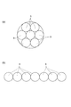
図2に示されるように、第1のコネクタ3は、ファイババンドル6の第1の端部7を収容するものである。第1のコネクタ3では、光ファイバ9は二次元配列(第1の配列)とされている(図4(a)参照)。第1のコネクタ3は、ファイババンドル6を保持する第1のフェルール11と、第1のフェルール11の一端11a側に取り付けられたスリーブ12と、第1のフェルール11の他端11b側に取り付けられたフェルールホルダ13と、を有している。また、第1のコネクタ3は、第1のフェルール11、スリーブ12及びフェルールホルダ13を収容するための第1のアダプタケース14を有している。すなわち、第1のアダプタ16とは、第1のアダプタケース14に第1のフェルール11、フェルールホルダ13及びスリーブ12が収容されたユニットである。更に、第1のコネクタ3は、第1のアダプタ16を収容するためのコネクタケース17を有している。
As shown in FIG. 2, the
第1のフェルール11は、筒状の部材であり、図5及び図6に示されるように、光軸Aの方向に沿って延びたファイバ挿通穴18を有している。このファイバ挿通穴18に複数の光ファイバ9が挿通されることにより、光ファイバ9は二次元配列されている(図4(a)参照)。ファイバ挿通穴18は、光ファイバ9を二次元状に配列保持するためのファイバ保持部18aと、光ファイバ9の保持状態を解除するための拡張部18bと、を有している。ファイバ保持部18aは、第1のフェルール11の一端11aから他端11bに向って形成され、一定の内径寸法を有している。拡張部18bは、第1のフェルール11の他端11b側に形成され、一端11aから他端11bへ向かう方向に沿って内径寸法が拡大するすり鉢状の形状を有している。
The
スリーブ12は、筒状の部材であり、光軸Aの方向に沿って延びたフェルール保持穴12aを有している。このフェルール保持穴12aは、第1のフェルール11の外径寸法と略同じ内径寸法とされている。スリーブ12の一端側から第1のフェルール11が挿入されている。そして、スリーブ12の他端側から別の接続部材が挿入されて第1のフェルール11の一端11aに突き当てられることにより、光ファイバ同士が光結合される。
The
フェルールホルダ13は、第1のフェルール11の他端11bから延出したファイババンドル6を保護するものである。フェルールホルダ13は、第1のフェルール11のファイバ挿通穴18と連通するファイバ挿通穴13aを有している。ファイバ挿通穴13aは、第1のフェルール11の他端11bにおけるファイバ挿通穴18の穴径よりも僅かに大きい内径寸法を有している。ファイババンドル6は、スリーブ12が接続されたフェルールホルダ13の一端側からファイバ挿通穴13aに導かれ、フェルールホルダ13の他端側から延出している。また、ファイバ挿通穴13aの内部では、ファイババンドル6を構成する光ファイバ9は接着剤19により互いに接着されている。また、ファイバ挿通穴13aの内部では、ファイババンドル6を構成する光ファイバ9はファイバ挿通穴13aの内壁面にも接着されている。
The
図2に示されるように、第1のアダプタケース14は、フェルールホルダ13を保持するホルダ保持部14aと、スリーブ12を保持するスリーブ保持部14bとを有している。これらホルダ保持部14aとスリーブ保持部14bとは、光軸Aの方向に並設されている。
As shown in FIG. 2, the
コネクタケース17は、第1のアダプタ16を収容すると共に第1のアダプタ16をハウジング2に固定するためのものである。コネクタケース17は、中空の直方体形状を呈し、ハウジング2に固定するための第1のフランジ17aを有している。この第1のフランジ17aとハウジング2の端壁とがボルト等で共締めされることにより、コネクタケース17がハウジング2に対して固定されている(図1参照)。
The
第2のコネクタ4は、ファイババンドル6の第2の端部8を収容するものである。第2のコネクタ4では、光ファイバ9は一次元配列(第2の配列)とされている(図4(b)参照)。第2のコネクタ4は、第2のフェルール21と、フェルールプッシュ22と、ゴムフード23とを有している。第2のフェルール21は、ファイババンドル6を保持するものである。フェルールプッシュ22は、第2のフェルール21の一端21aに当接している。ゴムフード23は、第2のフェルール21とフェルールプッシュ22とに亘って配置されている。
The
また、第2のコネクタ4は、第2のフェルール21、フェルールプッシュ22及びゴムフード23を一体化するためのアダプタボディ24を有している。すなわち、第2のアダプタ26とは、第2のフェルール21と、フェルールプッシュ22と、ゴムフード23とがアダプタボディ24によって一体化されたユニットである。
The
第2のフェルール21は、光軸Aの方向に沿って延びたファイバ保持部(第2のファイバ穴)21dを有している。このファイバ保持部21dは、光軸Aの方向と直交する方向に沿って光ファイバ9を挟み込んで一次元状に配列保持するものである。第2のフェルール21は、第2のアダプタ26に対して位置決めする一対の第1の位置決め穴21bを有している。一対の第1の位置決め穴21bは、ファイバ保持部21dを挟むように設けられている。すなわち、ファイバ保持部21dは、一対の第1の位置決め穴21b間に設けられている。
The
フェルールプッシュ22は、第2のフェルール21をアダプタボディ24に取り付けるためのものである。フェルールプッシュ22は、第2のフェルール21のファイバ保持部21dと連通するファイバ挿通部22aと、ファイバ挿通部22aを挟むように設けられた一対の第2の位置決め穴22bと、一対の第2の位置決め穴22bを挟むように設けられた一対の固定爪22cを有している。ファイバ挿通部22aは、ゴムフード23の外径寸法と略同じ内径寸法を有し、ゴムフード23が配置されている。一対の第2の位置決め穴22bは、第2のフェルール21における第1の位置決め穴21bと連通している。第1の位置決め穴21bと第2の位置決め穴22bとにガイドピンが挿入されることにより、フェルールプッシュ22に対して第2のフェルール21が位置決めされる。一対の固定爪22cは、光軸Aの方向に延在し、それぞれの先端部にはアダプタボディ24に引っ掛けられる爪部が設けられている。
The
ゴムフード23は、フェルールプッシュ22のファイバ挿通部22aと、第2のフェルール21のファイバ保持部21dとに亘って配置されている。ゴムフード23には、ファイババンドル6が挿通されるファイバ挿通穴23aが設けられている。このファイバ挿通穴23aは、光ファイバ9を所定の方向に並べたときの幅と高さと略同じ矩形状の内径寸法を有している。
The
アダプタボディ24は、第2のアダプタ26を収容すると共に第2のアダプタ26をハウジング2に固定するためのものである。アダプタボディ24は、第2のフェルール21を保持するためのフェルール保持部24aと、第2のアダプタ26の固定爪22cと係合する爪係合部24bとを有している。また、アダプタボディ24は、ハウジング2に固定するための第2のフランジ24cを有している。この第2のフランジ24cがハウジング2の端壁とがボルト等で共締めされることにより、アダプタボディ24がハウジング2に対して固定されている(図1参照)。なお、アダプタボディ24の出力端面24dと、第1のフェルール11の一端11aまでの長さは、例えば40mmである(図3参照)。
The
ファイババンドル6は、複数の光ファイバ9を備えている。複数の光ファイバ9のそれぞれは、複数の光路をなしている。図7に示されるように、ファイババンドル6は、第1のコネクタ3の内部に配置された第1の端部7と、第2のコネクタ4の内部に配置された第2の端部8とを有している。より詳細には、第1の端部7は、第1のフェルール11に配置され、第2の端部8は、第2のフェルール21に配置されている。ファイババンドル6では、第1の端部7から第2の端部8に向かって、第1の配列部L1と、配列変換部L2と、第2の配列部L3とがこの順に設けられている。
The
第1の配列部L1では、ファイババンドル6を構成する複数の光ファイバ9が第1の配列(図4(a)参照)で保持されている。この第1の配列部L1は、第1のフェルール11におけるファイバ保持部18aの範囲に形成されている。
In the first array portion L1, a plurality of
配列変換部L2では、ファイババンドル6を構成する複数の光ファイバ9が第1の配列から第2の配列に変換されている。この配列変換部L2は、第1のフェルール11における拡張部18bの範囲と、フェルールホルダ13のファイバ挿通穴13aの範囲と、フェルールホルダ13から延出した所定長さの領域M1の範囲に形成されている。すなわち、配列変換部L2は、第1の端部7を含む第1の配列部L1と第2の配列部L3との間に設けられている。
In the array conversion unit L2, the plurality of
第2の配列部(延在部)L3では、ファイババンドル6を構成する複数の光ファイバ9が第2の配列(図4(b)参照)で保持されている。第2の配列部L3は、第2のコネクタ4のゴムフード23から延出した所定長さの領域M2の範囲と、ゴムフード23のファイバ挿通穴23aの範囲と、第2のフェルール21におけるファイバ保持部21dの範囲に形成されている。すなわち、第2の配列部L3は、第1の端部7と第2の端部8との間に設けられている。
In the second array portion (extension portion) L3, the plurality of
更に、ファイババンドル6は、複数の光ファイバ9が互いに接着された部分と接着されていない部分とを有している。ここで、複数の光ファイバ9が互いに接着された部分をリボン部と呼び、複数の光ファイバ9が互いに接着されていない部分を非リボン部と呼ぶ。本実施形態のファイババンドル6は、第1のリボン部R1と、第2のリボン部R2と、第3のリボン部R3と、を有している。
Further, the
第1のリボン部R1は、配列変換部L2の一部と第2の配列部L3の一部とに亘って形成されている。より詳細には、第1のリボン部R1は、配列変換部L2において、フェルールホルダ13から延出した領域M1と、当該領域M1に連続する第2の配列部L3とに亘って連続するように形成されている。ここで、第1のリボン部R1を形成するための接着剤は、フェルールホルダ13のファイバ挿通穴13aにおける接着剤19(図5参照)とは一体化されていない。
The first ribbon part R1 is formed across a part of the array conversion part L2 and a part of the second array part L3. More specifically, the first ribbon portion R1 is continuous in the arrangement conversion portion L2 across the region M1 extending from the
第2のリボン部R2は、第2の配列部L3の一部に形成されている。より詳細には、ゴムフード23から延出した部分M3と、ゴムフード23に配置された部分M4と、第2のフェルール21に配置された部分M6とに亘って連続するように形成されている。なお、第2のリボン部R2は、第2の端部8には形成されていない。
The second ribbon portion R2 is formed on a part of the second array portion L3. More specifically, it is formed so as to continue over a portion M3 extending from the
第3のリボン部R3は、第1のリボン部R1と第2のリボン部R2との間に亘って形成されている。この第3のリボン部R3は、第1のリボン部R1と連続するように形成されると共に、第2のリボン部R2とも連続するように形成されている。従って、本実施形態のファイババンドル6では、第1のリボン部R1と、第2のリボン部R2と、第3のリボン部R3とが連続している。
The third ribbon portion R3 is formed between the first ribbon portion R1 and the second ribbon portion R2. The third ribbon portion R3 is formed so as to be continuous with the first ribbon portion R1, and is also formed so as to be continuous with the second ribbon portion R2. Therefore, in the
なお、第3のリボン部R3が第1のリボン部R1と連続していなくてもよい。この場合には、ファイババンドル6は、第3のリボン部R3と第1のリボン部R1との間に光ファイバ9が互いに接着されていない非リボン部(不図示)を有することになる。また、第3のリボン部R3が第2のリボン部R2と連続していなくてもよい。この場合には、ファイババンドル6は、第3のリボン部R3と第2のリボン部R2との間に光ファイバ9が互いに接着されていない非リボン部(不図示)を有することになる。
Note that the third ribbon portion R3 may not be continuous with the first ribbon portion R1. In this case, the
次に、光ファイバ用配列変換アダプタ1の製造方法について説明する。図8(a)に示されるように、ファイババンドル6を第1のフェルール11に挿通させて、ファイバ挿通穴18において接着する。この工程では、ファイババンドル6を構成する光ファイバ9は互いに接着されていない。すなわち、ファイババンドル6はリボン化されていない。続いて、第1のフェルール11にファイババンドル6を接着(図5参照)した後に、図8(b)に示されるように、フェルールホルダ13を第1のフェルール11に固定する。
Next, a method for manufacturing the optical fiber
その後、図8(c)に示されるように、フェルールホルダ13から延出した部分に第1のリボン部R1を形成すると共に、第2の端部8側に第2のリボン部R2(図7参照)を形成する。接着剤を利用したリボン化の後、第2のリボン部R2における光ファイバ9の先端の被覆を除去する。そして、第2のリボン部R2をゴムフード23及び第2のフェルール21に挿入(図2参照)した後に接着する。
Thereafter, as shown in FIG. 8C, the first ribbon portion R1 is formed in the portion extending from the
ここで、ファイババンドル6は、一次元配列の状態でリボン化された第2のリボン部R2を有している。この第2のリボン部R2では、複数の光ファイバ9が接着剤により一体化されているために適度な弾性を有している。従って、一次元配列とされた複数の光ファイバ9を容易にゴムフード23及び第2のフェルール21に挿入することができる。
Here, the
続いて、図2に示されるように、第1のコネクタ3を作製する。第1のフェルール11にスリーブ12を被せた後に、第1のフェルール11とフェルールホルダ13とスリーブ12とを第1のアダプタケース14に配置する。その後、第1のアダプタ16をコネクタケース17に取り付けて、第1のコネクタ3が完成する。
Subsequently, as shown in FIG. 2, the
第1のコネクタ3の完成後、第2のコネクタ4を作製する。まず、ゴムフード23及び第2のフェルール21をフェルールプッシュ22に取り付ける。そして、これらゴムフード23と第2のフェルール21と第2のコネクタ4とをアダプタボディ24に取り付けて、第2のコネクタ4が完成する。
After the completion of the
そして、ファイババンドル6の第1のコネクタ3と第2のコネクタ4との間に延在する部分を接着剤を利用してリボン化し、第3のリボン部R3(図7参照)を形成する。最後に、第1のコネクタ3と第2のコネクタ4とをハウジング2に取り付けて、光ファイバ用配列変換アダプタ1が完成する(図1参照)。
And the part extended between the
ところで、比較例(特許文献1)に係る光接続部材では、光ファイバの配列が変換されている部分は所定長を必要とする場合がある。そして、この所定長を短くしようとした場合には、光損失の発生や光結合の信頼性が低下する虞がある。より詳細には、光ファイバの配列が変換される部分の曲げ勾配を大きくすると、光損失が発生する。一方、曲げ勾配を緩めて光損失の発生を抑制しようとすると配列が変換される部分の長さが長くなってしまう。 By the way, in the optical connection member according to the comparative example (Patent Document 1), the portion where the arrangement of the optical fibers is converted may require a predetermined length. If this predetermined length is to be shortened, there is a risk that optical loss will occur and the reliability of optical coupling will be reduced. More specifically, when the bending gradient of the portion where the arrangement of the optical fibers is converted is increased, light loss occurs. On the other hand, if the bending gradient is relaxed to suppress the generation of light loss, the length of the portion where the array is converted becomes longer.
また、光ファイバの配列が変換されている部分の所定長を短くすると、光ファイバの長さも短くなるため製造工程が煩雑化する虞がある。比較例に係る光コネクタを製造する場合には、まず、光ファイバが二次元配列される一端側に複数の光ファイバを二次元的に束ねて挿入しつつ固定する。その後、他端側に光ファイバを一次元的に配列しつつファイバ穴に挿入するものと考えられる。この光ファイバを一次元的に配列しつつファイバ穴に挿入する作業は、光ファイバの配列が変換されている部分の長さが短くなるに伴って作業の難易度が高くなる虞がある。 Further, if the predetermined length of the portion where the arrangement of the optical fibers is converted is shortened, the length of the optical fiber is also shortened, so that the manufacturing process may be complicated. When manufacturing the optical connector according to the comparative example, first, a plurality of optical fibers are two-dimensionally bundled and fixed to one end side where the optical fibers are two-dimensionally arranged. Thereafter, it is considered that the optical fiber is inserted into the fiber hole while being arranged one-dimensionally on the other end side. The operation of inserting the optical fibers into the fiber hole while arranging them one-dimensionally may increase the difficulty of the operation as the length of the portion where the arrangement of the optical fibers is converted becomes shorter.
本実施形態の光ファイバ用配列変換アダプタ1によれば、ファイババンドル6における光ファイバ9の配列が、配列変換部L2において一次元配列から二次元配列列に変換されている。そして、配列変換部L2が第1のリボン部R1を有しているため、ファイババンドル6の光ファイバ9は第1のリボン部R1において一次元配列に維持される。複数の光ファイバ9が一次元配列に維持されているために、ファイババンドル6の取り扱いが容易になる。ファイババンドル6の取り扱いの容易化によれば、第1のコネクタ3と第2のコネクタ4との間に延在するファイババンドル6における第2の配列部L3の長さを短くしつつ、この短縮化された第2の配列部L3をファイバ保持部21dに容易に配置することが可能になる。従って、第1のコネクタ3と第2のコネクタ4との配置間隔を短縮して光ファイバ用配列変換アダプタ1の小型化を達成しつつ、光ファイバ用配列変換アダプタ1の製造工程の複雑化を抑制できる。
According to the optical fiber
ファイババンドル6の第2の配列部L3は、第2の端部8側に設けられると共に第2のリボン部R2を有する。この構成によれば、ファイババンドル6の第2の端部8近傍において、複数の光ファイバ9が一次元配列に維持される。従って、ファイババンドル6をファイバ保持部21dへ挿入する作業が一層容易になる。
The second array portion L3 of the
ファイババンドル6は、第3のリボン部R3を有する。この構成によれば、第1のリボン部R1と第2のリボン部R2との間において、所定の方向における曲げ剛性と、所定の方向と交差する別の方向における曲げ剛性とに差が生じる。このため、ファイババンドル6を特定の方向にのみ撓ませて、ファイババンドル6の伸縮を吸収することが可能になる(図3参照)。従って、光ファイバ用配列変換アダプタ1の信頼性を高めることができる。
The
光ファイバ用配列変換アダプタ1は、配列変換部L2を収容するハウジング2を更に備えている。配列変換部L2は、ハウジング2により形成された収容空間Sに配置されている。この構成によれば、配列変換部L2がハウジング2に囲まれて保護される。従って、光ファイバ用配列変換アダプタ1の信頼性を高めることができる。
The optical fiber
光ファイバ用配列変換アダプタ1は、第1のコネクタ3に収容される第1のアダプタ16と、第2のコネクタ4に収容される第2のアダプタ26と、を更に備えている。第1のリボン部R1は、第1のアダプタ16から延出し、第2のリボン部R2は、第2のアダプタ26から延出している。この構成によれば、第1のアダプタ16から第1のリボン部R1が延出し、第2のアダプタ26から第2のリボン部R2が延出している。第1のアダプタ16又は第2のアダプタ26の近傍でファイババンドル6に曲げが生じた場合、光ファイバ9にダメージを与える虞がある。しかし、第1のアダプタ16からは第1のリボン部R1が延出しているため、第1のアダプタ16で光ファイバ9が保持されると共に第1のリボン部R1により曲げに対する耐力が高まっている。同様に、第2のアダプタ26からは第2のリボン部R2が延出しているため、第2のアダプタ26で光ファイバ9が保持されると共に第2のリボン部R2により曲げに対する耐力が高まっている。従って、ファイババンドル6の曲げ発生を抑制するブーツ等を設ける必要がないため、光ファイバ用配列変換アダプタ1の構造を簡素化できる。
The optical fiber
本発明は、前述した実施形態に限定されず、本発明の要旨を逸脱しない範囲で種々の変形が可能である。 The present invention is not limited to the above-described embodiments, and various modifications can be made without departing from the gist of the present invention.
図9に示されるように、光ファイバ用配列変換アダプタ1Aは、ファイババンドル6Aが第3のリボン部R3(図7参照)に替えて、第1のリボン部R1と第2のリボン部R2との間に設けられた非リボン部R4を有していてもよい。この非リボン部R4は、光ファイバ9が互いに接着されていない部分である。
As shown in FIG. 9, in the optical fiber
非リボン部R4を有するファイババンドル6Aによれば、ファイババンドル6Aの柔軟性が非リボン部R4において確保される。従って、ファイババンドル6Aは、非リボン部R4において所望の方向に容易に曲げることが可能になる。更に、ファイババンドル6Aを容易に取り扱うことが可能になるため、小型化された光ファイバ用配列変換アダプタ1Aを容易に製造することができる。すなわち、非リボン部R4を有するファイババンドル6Aによれば、第1のリボン部R1と第2のリボン部R2との間において、曲げ剛性の低い部分が形成される。従って、所望の方向にファイババンドル6Aを曲げることができる。
According to the
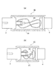
また、図10(a)に示されるように、ファイババンドル6Bは、第1のコネクタ3と第2のコネクタ4との間において、8の字状に捲き回されてハウジング2B内に収容されていてもよい。このようなファイババンドル6Bの収納形態によれば、第1のコネクタ3と第2のコネクタ4との間の間隔を短くすることが可能になる。また、図10(b)に示されるように、第1のコネクタ3と第2のコネクタ4との間を一層近接させたハウジング2C内にファイババンドル6Cを収容することも可能である。従って、光ファイバ用配列変換アダプタ1B,1Cは、長手方向について一層の小型化が可能である。
Further, as shown in FIG. 10A, the
1,1A,1B,1C…光ファイバ用配列変換アダプタ、2,2B,2C…ハウジング、3…第1のコネクタ、4…第2のコネクタ、6,6A…ファイババンドル、7…第1の端部、8…第2の端部、9…光ファイバ(光路)、11…第1のフェルール、11a…一端、11b…他端、12…スリーブ、12a…フェルール保持穴、13…フェルールホルダ、13a…ファイバ挿通穴、14…第1のアダプタケース、14a…ホルダ保持部、14b…スリーブ保持部、16…第1のアダプタ、17…コネクタケース、17a…第1のフランジ、18…ファイバ挿通穴(第1のファイバ穴)、18a…ファイバ保持部、18b…拡張部、19…接着剤、21…第2のフェルール、21a…一端、21b…第1の位置決め穴、21d…ファイバ保持部(第2のファイバ穴)、22…フェルールプッシュ、22a…ファイバ挿通部、22b…第2の位置決め穴、22c…固定爪、23…ゴムフード、23a…ファイバ挿通穴、24…アダプタボディ、24a…フェルール保持部、24b…爪係合部、24c…第2のフランジ、24d…出力端面、26…第2のアダプタ、A…光軸、L1…第1の配列部、L2…配列変換部、L3…第2の配列部(延在部)、M1,M2…領域、M3,M4,M6…部分、R1…第1のリボン部、R2…第2のリボン部、R3…第3のリボン部、R4…非リボン部、S…収容空間。
DESCRIPTION OF
Claims (6)
前記複数の光路を有し、第1の端部では前記複数の光路が第1の配列とされ、第2の端部では前記複数の光路が第2の配列とされたファイババンドルと、
前記第1の端部を収容し、前記複数の光路を前記第1の配列で保持するための第1のファイバ穴を有する第1のコネクタと、
前記第2の端部を収容し、前記複数の光路を前記第2の配列で保持するための第2のファイバ穴を有する第2のコネクタと、
を備え、
前記ファイババンドルは、前記第1の端部と前記第2の端部との間に設けられると共に前記複数の光路が前記第2の配列とされた延在部と、前記第1の端部と前記延在部との間に設けられると共に前記複数の光路の配列が前記第1の配列から前記第2の配列に変換される配列変換部と、を有し、
前記配列変換部は、前記複数の光路が互いに固定された第1のリボン部を有する、光ファイバ用配列変換アダプタ。 In an optical fiber array conversion adapter that converts an array of multiple optical paths,
A fiber bundle having the plurality of optical paths, wherein the plurality of optical paths are in a first array at a first end, and the plurality of optical paths are in a second array at a second end;
A first connector having a first fiber hole for receiving the first end and holding the plurality of optical paths in the first array;
A second connector having a second fiber hole for receiving the second end and holding the plurality of optical paths in the second array;
With
The fiber bundle is provided between the first end and the second end, and the plurality of optical paths are in the second arrangement, and the first end An array conversion section provided between the extension section and the array of the plurality of optical paths is converted from the first array to the second array;
The said array conversion part is an array conversion adapter for optical fibers which has a 1st ribbon part to which these optical paths were mutually fixed.
前記第1の配列は、二次元状の配列であり、
前記第2の配列は、一次元状の配列である、
請求項2に記載の光ファイバ用配列変換アダプタ。 The fiber bundle includes a third ribbon portion that is provided between the first ribbon portion and the second ribbon portion and the plurality of optical paths are fixed to each other.
The first array is a two-dimensional array;
The second array is a one-dimensional array.
The optical fiber array conversion adapter according to claim 2.
前記配列変換部は、前記ハウジングにより形成された収容空間に配置されている、請求項1〜4の何れか一項に記載の光ファイバ用配列変換アダプタ。 It further comprises a housing for accommodating the array conversion part,
The optical fiber array conversion adapter according to any one of claims 1 to 4, wherein the array conversion unit is disposed in a housing space formed by the housing.
前記第2のコネクタに収容される第2のアダプタと、を更に備え、
前記第1のリボン部は、前記第1のアダプタから延出し、
前記第2のリボン部は、前記第2のアダプタから延出している、請求項2〜5の何れか一項に記載の光ファイバ用配列変換アダプタ。
A first adapter housed in the first connector;
A second adapter housed in the second connector;
The first ribbon portion extends from the first adapter,
The optical fiber array conversion adapter according to any one of claims 2 to 5, wherein the second ribbon portion extends from the second adapter.
Priority Applications (1)
| Application Number | Priority Date | Filing Date | Title |
|---|---|---|---|
| JP2014040579A JP2015166757A (en) | 2014-03-03 | 2014-03-03 | Optical fiber array conversion adapter |
Applications Claiming Priority (1)
| Application Number | Priority Date | Filing Date | Title |
|---|---|---|---|
| JP2014040579A JP2015166757A (en) | 2014-03-03 | 2014-03-03 | Optical fiber array conversion adapter |
Publications (1)
| Publication Number | Publication Date |
|---|---|
| JP2015166757A true JP2015166757A (en) | 2015-09-24 |
Family
ID=54257670
Family Applications (1)
| Application Number | Title | Priority Date | Filing Date |
|---|---|---|---|
| JP2014040579A Pending JP2015166757A (en) | 2014-03-03 | 2014-03-03 | Optical fiber array conversion adapter |
Country Status (1)
| Country | Link |
|---|---|
| JP (1) | JP2015166757A (en) |
Cited By (7)
| Publication number | Priority date | Publication date | Assignee | Title |
|---|---|---|---|---|
| JP2019191369A (en) * | 2018-04-25 | 2019-10-31 | 住友電気工業株式会社 | Optical connection component and method for manufacturing optical connection component |
| JP2021067806A (en) * | 2019-10-23 | 2021-04-30 | 住友電気工業株式会社 | Optical fiber module and optical switch |
| JP2022132153A (en) * | 2021-02-26 | 2022-09-07 | ティーイー コネクティビティ サービシーズ ゲーエムベーハー | cable assembly |
| JPWO2023105836A1 (en) * | 2021-12-08 | 2023-06-15 | ||
| JP2024503566A (en) * | 2021-01-21 | 2024-01-26 | 浜松ホトニクス株式会社 | spectrally shaped light source |
| US12176200B2 (en) | 2021-05-24 | 2024-12-24 | Hamamatsu Photonics K.K. | Laser-driven light source with electrodeless ignition |
| US12578076B2 (en) | 2023-06-05 | 2026-03-17 | Hamamatsu Photonics K.K. | Dual-output laser-driven light source |
Citations (3)
| Publication number | Priority date | Publication date | Assignee | Title |
|---|---|---|---|---|
| JP2006171251A (en) * | 2004-12-15 | 2006-06-29 | Tomoegawa Paper Co Ltd | Optical fiber structure and manufacturing method thereof |
| WO2012121318A1 (en) * | 2011-03-09 | 2012-09-13 | 古河電気工業株式会社 | Optical connector, method for aligning multi-core fiber and bundle structure, and fiber arrangement conversion member |
| JP2013045018A (en) * | 2011-08-25 | 2013-03-04 | Sumitomo Electric Ind Ltd | Optical fiber ribbon and optical module |
-
2014
- 2014-03-03 JP JP2014040579A patent/JP2015166757A/en active Pending
Patent Citations (3)
| Publication number | Priority date | Publication date | Assignee | Title |
|---|---|---|---|---|
| JP2006171251A (en) * | 2004-12-15 | 2006-06-29 | Tomoegawa Paper Co Ltd | Optical fiber structure and manufacturing method thereof |
| WO2012121318A1 (en) * | 2011-03-09 | 2012-09-13 | 古河電気工業株式会社 | Optical connector, method for aligning multi-core fiber and bundle structure, and fiber arrangement conversion member |
| JP2013045018A (en) * | 2011-08-25 | 2013-03-04 | Sumitomo Electric Ind Ltd | Optical fiber ribbon and optical module |
Cited By (14)
| Publication number | Priority date | Publication date | Assignee | Title |
|---|---|---|---|---|
| JP2019191369A (en) * | 2018-04-25 | 2019-10-31 | 住友電気工業株式会社 | Optical connection component and method for manufacturing optical connection component |
| JP7087631B2 (en) | 2018-04-25 | 2022-06-21 | 住友電気工業株式会社 | Manufacturing method of optical connection parts and optical connection parts |
| JP2021067806A (en) * | 2019-10-23 | 2021-04-30 | 住友電気工業株式会社 | Optical fiber module and optical switch |
| JP7279611B2 (en) | 2019-10-23 | 2023-05-23 | 住友電気工業株式会社 | Optical fiber module and optical switch |
| JP7801406B2 (en) | 2021-01-21 | 2026-01-16 | 浜松ホトニクス株式会社 | Spectrally shaped light source |
| JP2025004159A (en) * | 2021-01-21 | 2025-01-14 | 浜松ホトニクス株式会社 | Spectrally shaped light source |
| JP2024503566A (en) * | 2021-01-21 | 2024-01-26 | 浜松ホトニクス株式会社 | spectrally shaped light source |
| JP7570515B2 (en) | 2021-01-21 | 2024-10-21 | 浜松ホトニクス株式会社 | Spectrally shaped light source |
| JP2022132153A (en) * | 2021-02-26 | 2022-09-07 | ティーイー コネクティビティ サービシーズ ゲーエムベーハー | cable assembly |
| US12176200B2 (en) | 2021-05-24 | 2024-12-24 | Hamamatsu Photonics K.K. | Laser-driven light source with electrodeless ignition |
| WO2023105836A1 (en) * | 2021-12-08 | 2023-06-15 | 株式会社フジクラ | Optical cable structure and optical cable structure production method |
| JP7637795B2 (en) | 2021-12-08 | 2025-02-28 | 株式会社フジクラ | Optical cable structure and method for manufacturing the optical cable structure |
| JPWO2023105836A1 (en) * | 2021-12-08 | 2023-06-15 | ||
| US12578076B2 (en) | 2023-06-05 | 2026-03-17 | Hamamatsu Photonics K.K. | Dual-output laser-driven light source |
Similar Documents
| Publication | Publication Date | Title |
|---|---|---|
| JP2015166757A (en) | Optical fiber array conversion adapter | |
| US9989711B2 (en) | Fiber optic connector and fiber optic cable assembly with fiber optic cable anchored to boot of fiber optic connector | |
| JP5899313B2 (en) | Optical fiber connector and its assembly method | |
| US20170212313A1 (en) | Fiber optic connector and fiber optic cable assembly with fiber optic cable anchored to boot of fiber optic connector | |
| JP2010286548A (en) | Multi-core fiber and optical connector including the same | |
| CN103608709B (en) | Optical connection member, optical connection structure, and manufacturing method of optical connection member | |
| JP5918869B2 (en) | High density optical fiber connector and method of assembling the same | |
| EP2453271A1 (en) | Mini type double-core optical fiber connector | |
| JP2010286661A (en) | Fiber array and optical connector including the same | |
| JP2015166818A (en) | Alignment conversion adaptor for optical fiber | |
| JP6307539B2 (en) | Optical connector with optical fiber and manufacturing method thereof | |
| JP2019113596A (en) | Optical connection structure | |
| JP2016061944A (en) | Fan-out parts | |
| JP4575869B2 (en) | Optical module | |
| JP4210268B2 (en) | Optical module | |
| KR20100089454A (en) | Optical connector | |
| JP2015034944A (en) | Optical connector | |
| JP6949367B2 (en) | Fiber optic connection structure and fiber optic module for connection | |
| US12535642B2 (en) | Optical fiber bundle connector and method of manufacturing optical fiber bundle connector | |
| CN223092175U (en) | A MPO Yin-Yang Attenuator | |
| JP2013020229A (en) | Optical connection member and optical connection structure | |
| CN104769470B (en) | For terminating contact pin and the female terminal assembly of optical cable | |
| JP4064949B2 (en) | Embedded wall type optical fiber outlet device | |
| JP2013213934A (en) | Optical connection member and manufacturing method for the same | |
| JP4472111B2 (en) | Optical fiber branch core with multi-fiber optical connector |
Legal Events
| Date | Code | Title | Description |
|---|---|---|---|
| A977 | Report on retrieval |
Free format text: JAPANESE INTERMEDIATE CODE: A971007 Effective date: 20160108 |
|
| A131 | Notification of reasons for refusal |
Free format text: JAPANESE INTERMEDIATE CODE: A131 Effective date: 20160126 |
|
| A02 | Decision of refusal |
Free format text: JAPANESE INTERMEDIATE CODE: A02 Effective date: 20160607 |